

 Thanks: 0
 Likes: 0
 Needs Pictures: 0
 Picture(s) thanks: 0
Results 1 to 15 of 34
Thread: How do I make this part?
-
5th April 2009, 10:41 PM #1
 Intermediate Member


- Join Date
- May 2008
- Location
- Melbourne
- Posts
- 48
 How do I make this part?
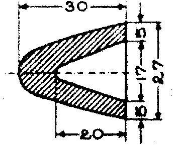
I'm embarking on a lengthy project and have been stumped by a part that needs routing/spindling out. But because of the internal taper, I'm not sure how to do it:
Here's the cross section (in mm):
But it's not hollow along it's length, the hollow is 'scalloped' like this sketch (top view):
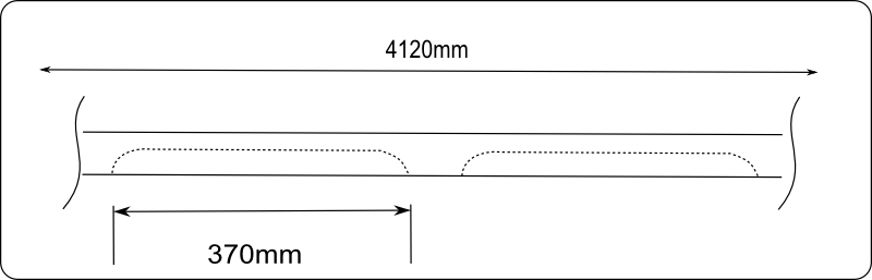
As you can see I need to do a few of the scallops along the length. There are four pieces like this.The material is Spruce so it's relatively easy to work (and it needs to be from a straight grained piece). Any suggestions?
-
5th April 2009 10:41 PM # ADSGoogle Adsense Advertisement
- Join Date
- Always
- Location
- Advertising world
- Posts
- Many
-
5th April 2009, 10:56 PM #2
GOLD MEMBER
- Join Date
- May 2003
- Location
- Kuranda, paradise, North Qld
- Age
- 62
- Posts
- 5,639
How accurate does it need to be? You could get a router bit custom made for the hollowed out section and make a jig to get the required length of cut and the scallops at the ends. You'd then be able to cut the outside with two passes on a saw canted over the the appropriate angle. This might require an angled packer attached to the fence for the second cut to keep everything aligned. Finally, two passes on a router table with an appropriate bit would round over the top.
Mick"If you need a machine today and don't buy it,
tomorrow you will have paid for it and not have it."
- Henry Ford 1938
-
5th April 2009, 11:52 PM #3
Intermediate Member
- Join Date
- May 2008
- Location
- Melbourne
- Posts
- 48
Thanks for the tip. I think I can shape the external profile fairly easily. I'd cut the two angles and then hand plane the curve and sand, using a profile cut out to check progress.
The internal section is the puzzler - where would I get a custom router bit?
-
6th April 2009, 08:50 AM #4
GOLD MEMBER
- Join Date
- May 2003
- Location
- Kuranda, paradise, North Qld
- Age
- 62
- Posts
- 5,639
Auswide Saw and Tooling on the Gold Coast could make one for you, there may be someone closer, but postage won't be a killer. You'll want to do the internal section first so that you have more timber to hang onto and bearing surface for the router. Originally Posted by brinesharks

Mick"If you need a machine today and don't buy it,
tomorrow you will have paid for it and not have it."
- Henry Ford 1938
-
6th April 2009, 09:48 PM #5
Sum ergo cogito (Cogito)
- Join Date
- Oct 2006
- Location
- Tallahassee FL USA
- Age
- 82
- Posts
- 4,650
The ends of the scallops should be the same shape as the cross section, not curved as shown; otherwise, the piece would have to be lifted gradually, perhaps by lifting ramps attached to the sides of the workpiece, to engage mating ramps attached to the router table. Ditto for starting the cuts.
If possible, the scallops might be slightly re-designed to exploit existing cutters, if there's anything close. Custom tooling might also impose some limitations on the shape.
Not for the faint-hearted, but a table saw can cut coves when fed on the bias. You'll need to experiment, to find a suitable combination of shapes and bias angle, as well as proper starting and end points on the workpiece. A small-diameter blade would likely be needed.
Cheers,
JoeOf course truth is stranger than fiction.
Fiction has to make sense. - Mark Twain
-
13th April 2009, 08:35 PM #6
Senior Member
- Join Date
- Mar 2008
- Location
- Australia
- Posts
- 141
I made a music stand with a profiled base part using a router to rough out the shape - multiple passes of round nose bit with small steps on fence and corresponding steps in depth (would have been easier with a better router). Finished with combination of plane, sandpaper, elbow grease.
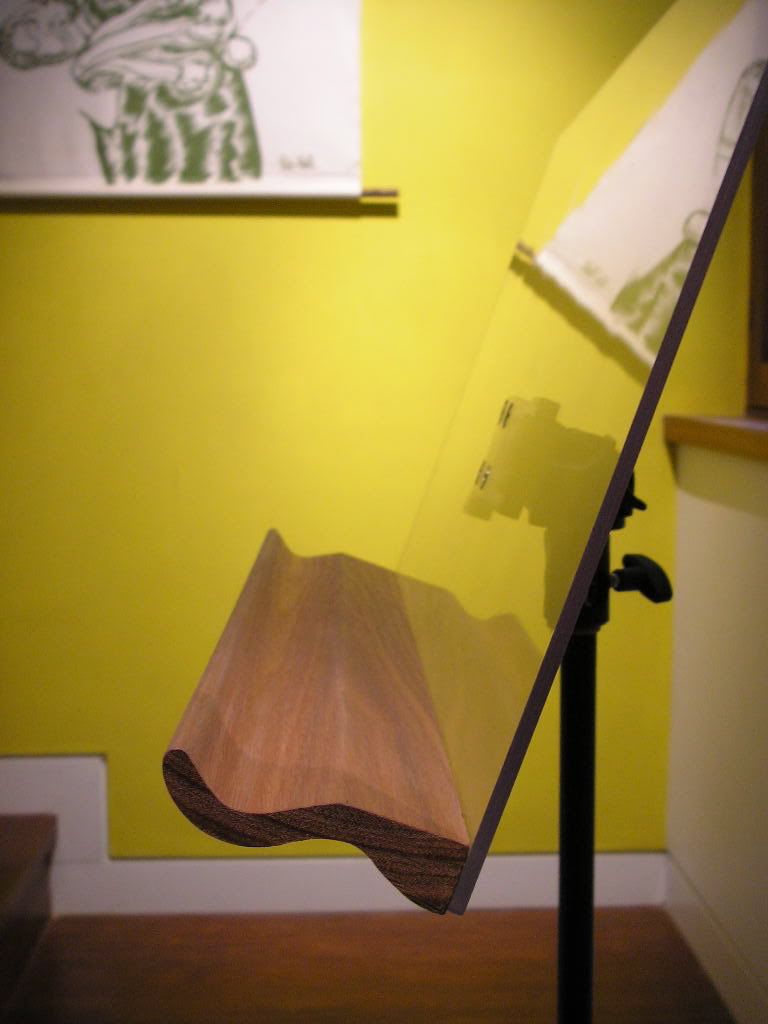
It is made of Jarrah.
-
13th April 2009, 09:31 PM #7
GOLD MEMBER
- Join Date
- Feb 2003
- Location
- back in Alberta for a while
- Age
- 68
- Posts
- 12,006
can you make the piece in two halves, glued together after cutting the internal shape?
ian
-
21st April 2009, 10:18 PM #8
Intermediate Member
- Join Date
- May 2008
- Location
- Melbourne
- Posts
- 48
Joe, the ends of the scallops are actually flared out a little more than my drawing. Your suggestion of the jig to bring the router in gradually would work nicely.
blouis79 - thanks for your suggestions! The music stand looks very nice.
I just realised I haven't mentioned what the project is - it's a Nieuport 17 aeroplane as per the original (1916) factory drawings - or as close as I can come to them! I figure I have at least 10 years of building ahead of me and a whole lot of learning! Not only does it need to look the part, it also has the be engineered to fly so any modifications to methods/materials need to be carefully considered. Here's a quick intro to the plane:
http://www.theaerodrome.com/aircraft...ieuport_17.php
ian - Making it in two halves is an option. The original design calls for a single piece, however the main wing spars (the main structural member of the wing that runs from the centre to the tip) are glued up from to spindled out pieces of Spruce with a ply I-beam let in to the centre. Externally they look solid but internally there is weeks of work - I plan to take a whole lot of photos to prove I actually did the work! The part I asked about in this thread is the Leading Edge of the wing which is not as critical structurally as the spars, so I guess I could make them in two halves. Might research this a bit more...
-
21st April 2009, 10:51 PM #9
GOLD MEMBER
- Join Date
- Feb 2003
- Location
- back in Alberta for a while
- Age
- 68
- Posts
- 12,006
Briney Originally Posted by brinesharks
put the router away and go and buy yourself a small to medium sized shaper and a large dust collector
for this sort of project you really need to go small scale industrial
I also suggest you investigate the cost of setting up to grind your own shaper knives and compare that to the cost of paying someone else to grind them for you
also be very mindful of the material you choose to use
in 1916, old growth (which usually means closely spaced growth rings) was all that was available
in 2009, you may find that the material specified is only available as plantation grown material which usually means wider growth rings and a possibly more brittle / weaker material
You may need to substitute species to retain tight growth rings and hence the assumed strength
ian
-
22nd April 2009, 06:42 PM #10
GOLD MEMBER
- Join Date
- Feb 2003
- Location
- back in Alberta for a while
- Age
- 68
- Posts
- 12,006
Briney
I've thought some more about your project
Your shop drawings are almost certainly based on using a combination of hand tools, machine tools and a flat bench longer than the longest piece in the plane.
apart from a saw and pedestal drill, the most likely machine tool used originally is a shaper.
It's most likely that the "flaring" in your description ...reflects either the diameter of the original shaper head or a combination of that diameter and the ramp on the jig used to carry the piece past the cutter head.the ends of the scallops are actually flared out a little more than my drawing
My assessment is that the purpose of the "scallops" is to reduce the weight of the member and that the shape of the ends is not material
However, the wall thickness of the member will be critical
too thin = not enough strength
too thick = too much weight
now unless you are planning on building an exact caopy of the original 1916 engine, I'd err on the side of slightly thicker than original as the power to weight ratio of a modern engine should more than compensate for any slight increase in weight of individual members in the airframe.
keep posting
ian
-
22nd April 2009, 08:31 PM #11
Intermediate Member
- Join Date
- May 2008
- Location
- Melbourne
- Posts
- 48
ian, Originally Posted by ian
Thanks for your response - you are certainly correct about the strength vs weight requirements. Many of the pieces in this era of aircraft (certainly British and French) were spindled out to save weight. The scallops in the Ni17 were a little unusual in that they weren't 'through' to the top and bottom surfaces like the Sopwith designs. I think the entry and exit is not entirely critical, as long as they aren't sudden and leave areas that might propagate a crack.
Carb-i-tool got back to me with a quote for a custom bit. Probably a fair price but more than I was hoping.
Regarding engines - this might come as a surprise but the original had a better power-to-weight ratio than modern engines. I am struggling to find a modern engine that can fit the space available and swing a big enough prop. The originals were true 'rotary' engines where the crankcase and all the cylinders rotated around a central mount. The prop was therefore mounted straight onto the front of the crankcase which all rotated together at around (max) 1300 RPM at 110hp. Using a modern engine I need around 225hp to get near the 110hp at a low RPM. Sounds strange but that's how the numbers come out. In the end I need to swing a 100" diameter prop just to clear the engine cowl! So the upshot is that I might need to use the original spec engine either rebuilt (risky and expensive) or a modern reproduction (again - risky and expensive but for different reasons!). No good solutions yet.
Keep the ideas coming! I have a lot of other pieces that have me foxed - will post them when I can...
-
22nd April 2009, 10:09 PM #12
Senior Member
- Join Date
- Nov 2006
- Location
- Thirroul, NSW
- Age
- 53
- Posts
- 102
WOW!
and I thought I had seen pretty much every conceivable project on these boards...?
this is very interesting, will be watching the developments with interest.
Keep posting, would love to see the end result.
-
22nd April 2009, 11:47 PM #13
GOLD MEMBER
- Join Date
- Feb 2003
- Location
- back in Alberta for a while
- Age
- 68
- Posts
- 12,006
Briney
would it be too much of a departure to install a variable pitch prop for flight?
if my very vague recollections from 30+ years ago are correct variable pitch props were develped to get around the high torque requirements of fixed pitch props.
ian
-
23rd April 2009, 09:13 AM #14
Senior Member
- Join Date
- Mar 2008
- Location
- Australia
- Posts
- 141
Thinking a bit more about the particular shape you have, I would do at home with guide rail plunge saw to start. The external and internal surfaces would be one cut each for the straight part. Router for the ends. A couple of well placed parallel cuts to meet the two originals at a V would remove most the the centre without turning it all into sawdust. Rout the floor of the cavity.
-
23rd April 2009, 05:42 PM #15
GOLD MEMBER
- Join Date
- Oct 2007
- Location
- Alexandra Vic
- Age
- 69
- Posts
- 2,810
With regard to power, have you considered this as a possibility. Not the original style as it is a radial rather than a rotary. However, a viable working Gnome (even for ground running) would be very rare.
Advantages I see are 110HP @ 2400RPM, (Gear reduction unit, might be able to supply a custom gear set for even lower RPM), round engine instead of flat or inline, much less of the ugly gyroscopic precession that the rotaries were famous for, plus it's designed and manufactured and serviced in Moorabin.
Hope this helps.


 Reply With Quote


Similar Threads
-
Second part of ...................
By Les in Red Deer in forum WOODTURNING - PEN TURNINGReplies: 9Last Post: 7th August 2008, 08:35 PM -
Want to make some furniture in Mordialloc and make some money.
By Lignum in forum ANNOUNCEMENTSReplies: 8Last Post: 23rd April 2007, 12:04 AM -
End of the World Part I
By Grunt in forum NOTHING AT ALL TO DO WITH WOODWORKReplies: 23Last Post: 1st November 2006, 07:01 PM -
The cat and I (part 2)
By Wongo in forum NOTHING AT ALL TO DO WITH WOODWORKReplies: 27Last Post: 21st April 2006, 11:58 AM
