

 Thanks: 0
 Likes: 0
 Needs Pictures: 0
 Picture(s) thanks: 0
Results 1 to 15 of 15
Thread: Understanding woodwork plans pt2
-
22nd March 2013, 05:10 PM #1
 Novice


- Join Date
- Oct 2010
- Location
- Sydney, Australia
- Posts
- 23
 Understanding woodwork plans pt2
Hi All,
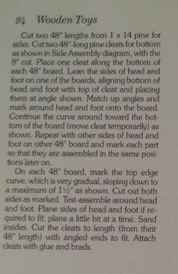
thanks everyone who helped with my first post asking about sourcing wood I was now a little confused by the side on plans for this ark toybox cradle I am going to attempt to build.
The only other bit I'm not overly getting based on the side view diagram is that they've said to cut some cleats to run along the side of each side of the crib.. they mention an 8 degree angle and in the side on diagram (attached), they have a bit of wood with an 8 degree angle and a 20 degree angle..
I'm just wondering if you understand what the angles are for I just can't picture it.. any way you could look at the diagram and explain what the 8 degrees is used for and where the 20 degrees comes from?
Thanks again!
Tom
-
22nd March 2013 05:10 PM # ADSGoogle Adsense Advertisement
- Join Date
- Always
- Location
- Advertising world
- Posts
- Many
-
22nd March 2013, 05:58 PM #2
The Laird
- Join Date
- Jan 2007
- Location
- Katoomba NSW
- Posts
- 4,771
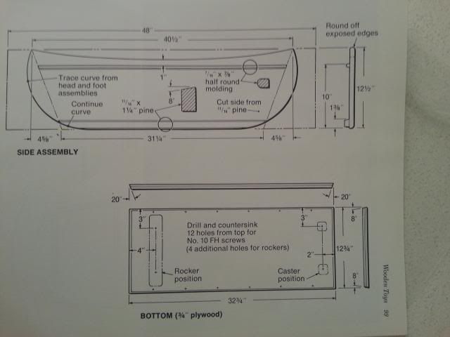
As far as I can make out, the head and foot are attached via cleats at 20° to the base. The sides are attached at 8° to the base.
Use the cleats to position the head and foot on the side boards and mark around them to give you the reference points for marking the curves. The sides are then cut to your curve marks.
I hope that was a bit clearer than those terrible directions.
I've just realised that the cleats have a compound cut. The long cleats have an 8° angle machined into one edge with a 20° cut on the ends.
For the small cleats a 20° angle machined into one edge with an 8° cut on the ends.
-
22nd March 2013, 07:11 PM #3
Novice
- Join Date
- Oct 2010
- Location
- Sydney, Australia
- Posts
- 23
thanks so much for such a detailed reply. .
I cant visualise it sorry so you'll have a cleat down each long side with a flat side attached to the side.. at the end you have a 20 degree angle so that the head and foot are angled out at 20 degrees?
the ply base of the arc is glued or nailed or both? to those cleats?
I dont get the 8 degrees and compound part sorry are you saying
there is a long cleat down each long side and then on each of the curved ends there's a cleat?
and if thats the case are the cleats mitred and join to form some kind of box shape?
is there a better way to express it in a diagram?
sorry it has me a little stumped
-
22nd March 2013, 07:39 PM #4
SENIOR MEMBER
- Join Date
- Dec 2005
- Location
- Canberra
- Posts
- 3,260
The sides of the cot splay out at 8 degrees, while the head and foot of the cot splay out at 20 degrees.
This means the base of the cot has a board with an 8 degree cut on the long edges and a 20 degree cut on the short edges.
thing.JPG
Probably the best way to try to understand it is to go to the nearest craft store and get a sheet of 5mm foamcore board and try to make a miniature version first....you'll soon see where you need to make angled and compound cuts.
-
22nd March 2013, 07:50 PM #5
Novice
- Join Date
- Oct 2010
- Location
- Sydney, Australia
- Posts
- 23
thanks so much for the reply!
that makes much more sense so there's no cleat along the short side where the foot and head go?
just one down each side? and they'd live on the underside of the base with thin nails and glue to splay the ends and aide out?
thanks so much for taking the time I do appreciate it!
-
22nd March 2013, 09:20 PM #6
The Laird
- Join Date
- Jan 2007
- Location
- Katoomba NSW
- Posts
- 4,771
Yes there are short cleats. They have a 20° angle on one edge and an 8° angle on the ends. They should slot in between the long cleats.
-
22nd March 2013, 09:35 PM #7
Novice
- Join Date
- Oct 2010
- Location
- Sydney, Australia
- Posts
- 23
thanks ncarcher but sorry then do they join like mitres? I just dont get how the base would look it says to attach the long cleats to the side but doesnt mention the shorter ones..
sorry I feel dense I just cant picture it
-
22nd March 2013, 09:54 PM #8
Senior Member
- Join Date
- Jan 2008
- Location
- Vevey, Switzerland
- Posts
- 407
I think the cleats are just to rest the plywood bottom on, because the sides will screw to the prow and stern, which are cut to the, presumably, 8 degree angle and so make a sturdy box. Originally Posted by thomen

I'd make the sides and ends and then cut the cleats to suit.
BTW If the 14 x 1 stuff is just for the sides you don't need 22' of it, that must be a misprint on the plans.Cheers, Glen
-
22nd March 2013, 10:06 PM #9
Novice
- Join Date
- Oct 2010
- Location
- Sydney, Australia
- Posts
- 23
thank you again for the replies.. I was going to make the bow and stern and cut out the sides and then think about the base/cleats I think im frustrated in that the side plan shows the cleat thats supposed to be attached to each side with a slight angle upward and I thought thats what the ply base was supposed to attach to but am wondering should the ply sit on top of the cleat and then nails go down from the top of the ply in to the cleat and the reason for the angle is so the sides splay out by 8 degrees.. that makes sense in my head but then the cleats that go on the end of the base is whats throwing me.. going horizontally.. theres no indication of how they attach or if they sit under the base just to provide the 20 degree angle..
-
22nd March 2013, 10:21 PM #10
The Laird
- Join Date
- Jan 2007
- Location
- Katoomba NSW
- Posts
- 4,771
In the attached sketch, top one shows the base with attached long cleats. Cleats left short of end. Second one shows short cleat attached to end of base, butted up against end of long cleat. Next two are alternative with short cleat positioned inside long cleats.
It appears from the drawing that the long cleats are attached to the base with 6 x No 10 FH screws. No mention of how short cleats are attached but that may be explained later(probably 4 screws). I'd say the sides are attached to the cleats, that's what cleats are for. It actually shows the cleat attached to the long side piece in the first drawing. Cleats are attached to sides with glue and brads
-
22nd March 2013, 10:39 PM #11
Novice
- Join Date
- Oct 2010
- Location
- Sydney, Australia
- Posts
- 23
thank you so so much that makes alot more sense I really do appreciate you taking the time!!
-
23rd March 2013, 10:37 AM #12
Intermediate Member
- Join Date
- Feb 2013
- Location
- Tasmania
- Posts
- 42
The ark from hell
I'm looking forward to see this completed
 .
.
By the end of this project Thomen You will be able to do anything, from any set of drawings
I hope it all comes together for you at the end.
Mark
-
23rd March 2013, 01:50 PM #13
Novice
- Join Date
- Oct 2010
- Location
- Sydney, Australia
- Posts
- 23
haha one can only hope! I really can't wait to get stuck in!
time to join a local men's shed or the like so I can get access to things like a table saw for bevelling etc!
I was thinking if this goes well then I'll have to make a 2nd one and donate it to the children's hospital or auction it off for a kids charity..
oh i can see there being a lot of learning!
Thanks again everyone for all your help!
-
9th April 2013, 09:38 PM #14
Intermediate Member
- Join Date
- Feb 2013
- Location
- Tasmania
- Posts
- 42
How is the ark coming on Thomen? I haven't seen anything posted
Have you got it sussed?
I hope you enjoy the use later.
Mark
-
9th April 2013, 11:34 PM #15
Novice
- Join Date
- Oct 2010
- Location
- Sydney, Australia
- Posts
- 23
Originally Posted by msrampant
I have got the plans sussed and ordered the pine! and joined a local men's shed I'll be there for the first time not this weekend but the one after.. being 30 it was hard to find one that took under 55 y/os but living in a unit it would have been tricky to set up a good workshop!

 Reply With Quote

Similar Threads
-
understanding wood requirements for plans
By thomen in forum WOODWORK - GENERALReplies: 13Last Post: 22nd March 2013, 11:46 AM -
Understanding Building Plans
By Mini in forum WOODWORK - GENERALReplies: 2Last Post: 2nd October 2012, 08:30 PM -
Free Woodwork Plans
By Hellacopter 1 in forum DESIGNS & PLANS FOR PROJECTSReplies: 7Last Post: 18th August 2004, 01:47 PM
