

 Thanks:
  Likes:
  Needs Pictures: 0
 Picture(s) thanks:
Results 1 to 15 of 19
Thread: Shaving width.
-
31st October 2018, 09:23 AM #1
 Deceased


- Join Date
- May 2008
- Location
- Australia
- Posts
- 2,357
 Shaving width.
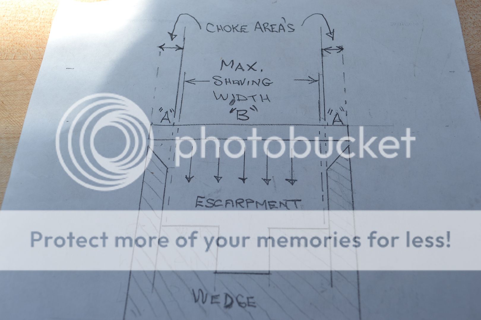
Specific to users of wooden bench planes with traditional wedge abutments; if your struggling with a build up of shavings within the abutment lines of the mouth opening, the correct use of camber to restrict the shaving width should alleviate this concern.


-
31st October 2018 09:23 AM # ADSGoogle Adsense Advertisement
- Join Date
- Always
- Location
- Advertising world
- Posts
- Many
-
31st October 2018, 04:32 PM #2
 GOLD MEMBER
- Join Date
- Mar 2006
- Location
- Earth
- Posts
- 3,567
The Japanese solve the same problem by grinding away the corners they call them ears. This avoids the choke problem.
EA2B6772-6DDF-49C6-A44B-4B2B981F7A48.jpeg
This is why Japanese plane blades have two width measurements the width of the blade and the effective cutting width of the blade.
-
31st October 2018, 05:21 PM #3
Be inspired. Be creative. Be bold.
- Join Date
- Apr 2001
- Location
- Perth
- Posts
- 10,820
Stewie, and all ...
Are we discussing smoothers or jack planes?
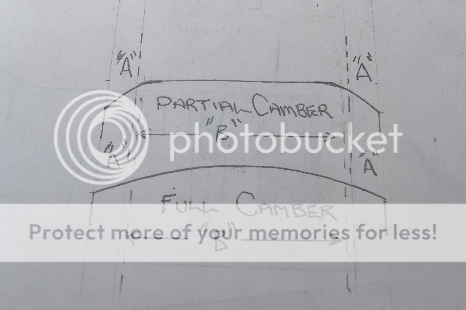
There are a couple of factors that stand out for me. Firstly, if this is about a blade in a smoother, the shape given to the partial camber is different to what most people are told to do as an alternative to cambering. Generally, I hear/read recommendations to "knock off the corners". Taken literally, this means just that - and the argument against this is that the transition is not changed. The track lines remain. What the drawing shows is a rounded corner, and I recall this being the method that Chris Schwarz advocates. He does this with a file (which begs the question how hard his blades are?! But that is by the way). The problem I see with this method is the bevel remains flat, but it is just a narrower bevel, and the issue now lies with maintaining a perfectly parallel blade to avoid a different type of surface treatment.
My preference has always been a full camber, since this permits a full width shaving (in theory - in practice one may over do the camber and limit it to the centre of the blade), with a minimal transition.
The camber here resembles one from a jack plane rather than a smoother. It is not made clear, Stewie, whether this is one or the other. The distinction is relevant, however, since a deeper camber demands a deeper shaving to become wider. A shallow shaving leads to a narrow shaving - the situation to which I referred above.
If the objective is to create a jack-type camber to take deeper shavings, then the clipped "corner-type approach" (even rounded clipped corner) is no longer a valid alternative; it is a separate type of blade treatment altogether and one may as well use a narrower plane with a narrower blade. If the target is a smoother, then I see a bunch of negatives.
Regards from Perth
DerekVisit www.inthewoodshop.com for tutorials on constructing handtools, handtool reviews, and my trials and tribulations with furniture builds.
-
31st October 2018, 05:22 PM #4
Be inspired. Be creative. Be bold.
- Join Date
- Apr 2001
- Location
- Perth
- Posts
- 10,820
Stewie, and all ...
Are we discussing smoothers or jack planes?
There are a couple of factors that stand out for me. Firstly, the shape given to the partial camber is different to what most people are told to do (as I understand - I am open to correction here ... this is one of the issues that stands out). Generally, I hear/read recommendations to "knock off the corners" as a substitute for cambering. Taken literally, this means just that - and the argument against this is that the transition is not changed. The track lines remain. What Stewie has drawn is a rounded corner, and I recall this being the method that Chris Schwarz advocates. He does this with a file (which begs the question how hard his blades are?!). The problem I see with this method is the bevel remains flat, but it is just a narrower bevel, and the issue now lies with maintaining a perfectly parallel blade to avoid a different type of surface treatment.
My preference has always been a full camber, since this permits a full width shaving (in theory - in practice one may over do the camber and limit it to the centre of the blade).
The camber here resembles one from a jack plane rather than a smoother. It is not made clear, Stewie, whether this is one or the other. The distinction is relevant, however, since a deeper camber demands a deeper shaving to become wider. This is the situation to which I referred above.
If the objective is to create a jack-type camber, then the clipped "corner-type approach" is no longer a valid alternative; it is a separate type of blade treatment.
Regards from Perth
DerekVisit www.inthewoodshop.com for tutorials on constructing handtools, handtool reviews, and my trials and tribulations with furniture builds.
-
31st October 2018, 07:39 PM #5
SENIOR MEMBER
- Join Date
- Oct 2009
- Location
- South Africa
- Posts
- 950
Something that has always puzzled me since I first read about putting camber on a blade is that you can no longer set your chip breaker as close to the cutting edge as what you can without a camber. I suppose I’m talking about smoothing here, as if you’re still dimensioning a board you’re less worried about a bit of tear out.
-
31st October 2018, 08:28 PM #6
GOLD MEMBER
- Join Date
- Mar 2006
- Location
- Earth
- Posts
- 3,567
From a Japanese view the removal of the corners is only done to prevent shaving getting jammed into the abutments. It has no relationship / influence on the crown of the blade.
I have also found that grinding the corners of the blade so that it�s a hair narrower then the backing iron. It makes it easy to tap into position the backing iron so it�s comes right up to very leading bevel edge of the blade. Because you can see the corners of backing iron sneak forward inside the mouth.
I add a camber to all but shooting planes. You stil need to add a camber even if you remove the corners. Because as Derek points out it�s near impossible to hone and adjust the blade perfectly square, as a flat/square blade will always leave tracks. The radius of the camber is per usual relative to the intended function of the plane.
Colin the answer to your question is to camber the backing iron to match your blade.
-
31st October 2018, 09:10 PM #7
SENIOR MEMBER
- Join Date
- Jul 2008
- Location
- Aspley, Brisbane
- Age
- 46
- Posts
- 362
You can still apply a full camber on a smoothing plane blade, allowing appropriate cap iron placement. Originally Posted by Colin62

https://www.popularwoodworking.com/c...-honing-guide/
Regards,
Denim
-
31st October 2018, 11:28 PM #8
Be inspired. Be creative. Be bold.
- Join Date
- Apr 2001
- Location
- Perth
- Posts
- 10,820
Hi Denim
That pop wood link is dated 2009. That is long before Chris Schwarz or David Charlesworth (both on the blog post) learned to set the chipbreaker (which they did in 2013). So they talk of it being set 1/16" back. Even 1/32" (0.7mm) back would be too far back to have any effect. For most work, a smoother needs the chipbreaker around 0.4mm from the edge of the blade.
Keep in mind that the average smoother shaving is around 0.05mm thick. The camber is not much more than this. Therefore the reduced curve at the corners if a blade are around 0.1mm. This is not going to have any effect on the edge of the shaving. No need to camber a chipbreaker.
Regards from Perth
DerekVisit www.inthewoodshop.com for tutorials on constructing handtools, handtool reviews, and my trials and tribulations with furniture builds.
-
1st November 2018, 02:33 PM #9
Deceased
- Join Date
- May 2008
- Location
- Australia
- Posts
- 2,357
Fettling-in a traditional wooden bed.
There are 2 critical areas on a traditional wooden bed that need to be making sound contact with the back of the plane iron. At the bottom of the bed (the given height should exceed the plane irons primary bevel), and at the very top of the bed (1/2" as a general rule). The remaining surface of the bed is of less importance and is worked back lightly to achieve a slight clearance.
Within the following photo the chalk transfer marks have highlighted there is excellent contact being made within those 2 critical areas of the bed, but the less critical area (marked X) needs some further working back to achieve an ideal clearance.
Getting closer.

Now showing correct contact is being made across the full surface of the bed.


-
2nd November 2018, 04:35 PM #10
Deceased
- Join Date
- May 2008
- Location
- Australia
- Posts
- 2,357
Colin; there is another option available that doesn't require the leading edge of the cap iron to be set within the distance of a bees scrotum. By adding a micro back bevel to the back of the irons cutting edge the effective pitch can be raised above that being governed by the planes bed. As an example, if your starting point is a 45 degree bed, by adding a 5 degree back bevel that will raise the effective pitch to york pitch (50 degrees) 10 degrees =middle pitch (55 degrees) 15 degrees =cabinet pitch (60 degrees). Originally Posted by Colin62
On the following wooden jointer plane, the leading edge of the cap iron has a clearance gap of 1/16" (1.5mm). It has a 45 degree bed with an additional 10 degree back bevel to raise the effective pitch from common pitch to middle pitch. If tear-out was still occurring, I can opt to increase the back bevel by a further 5 degrees to cabinet pitch.
Stewie;

-
4th November 2018, 03:19 AM #11
SENIOR MEMBER
- Join Date
- Oct 2009
- Location
- South Africa
- Posts
- 950
Thanks to everyone who replied on the subject of chip breakers and camber.
I'm not sure which I'd bugger up worse - trying to camber the chip breaker while still keeping the angle consistent across the face of it, or trying to get a cambered back bevel. That makes the advice of not worrying about camber on the chip breaker at all quite appealing. I suppose it's a case of learning what I can by reading and then going out to the workshop and finding a system that works for me on a practical level, with the kit and skills that I have.
-
4th November 2018, 09:51 AM #12
GOLD MEMBER
- Join Date
- Jun 2005
- Location
- Helensburgh
- Posts
- 7,696
I don't see how a chipbreaker can be cambered and how it can keep the same pressure on the blade from side to side. If material is removed to form the camber then the CB cannot exert the same pressure right across the blade????? I would be interested to read others view on this. Originally Posted by Colin62
CHRIS
-
4th November 2018, 12:22 PM #13
Deceased
- Join Date
- May 2008
- Location
- Australia
- Posts
- 2,357
The following article is from Brent Beach; The Sharpening FAQ - Fads and fallacies
Chip breakers break chips, right?
Most bench planes have a double iron. That is, a second iron is attached to the plane blade. This second iron sits on top, with its leading edge parallel to and near the cutting edge. Some people call this second iron a chip breaker. Early in my blade testing, when looking at the upper surface of plan irons, I noticed that the wear on the upper surface was all near the edge. How near? Within 0.004" of the edge.
It occurred to me that this meant that the upper surface within 0.004" of the edge was breaking the chip, not the chip breaker that was set about 10 times farther back from the edge. This was when I started calling the second iron a cap iron.
In this rather extended discussion, I will suggest that most of the time the second iron does not break the chip. In fact, for many people, it has never broken the chip and never will. For some people who are working particular kinds of wood, who have achieved a high level of expertise in woodworking, and who have read enough in the right places, the second iron will some of the time, break chips.
Rather than name the second iron for a feature that is almost never used, I prefer to use the term cap iron, a name for the function that it always performs.
For a component of the plane that is often overlooked, the complexity of the function of the cap iron is counter-intuitive. This discussion attempts to look into all the nooks and crannies. If you interested, I hope the information you need to satisfy your interest is here. Somewhere here.
Negative Evidence
First, the bad news. Well, not exactly news. Rather, the negative evidence. First, then, the reasons why I believe that the cap iron is only rarely needed for chip breaking. (This does not mean you don't need the cap iron, just that a lot of the time it does no chip breaking.)
My Experience
 My examination of the upward facing surface of plane blades after use (see my bevels page) made it clear to me that all of the forceful contact between the shaving and the blade occurred within 0.004" of the edge. After moving that far past the edge, the shaving had curled away from the upper face of the blade. The fibres in the shaving had bent or broken. Those fibres were no longer able to exert sufficient force back along the shaving to lift fibres ahead of the edge - the cause of tearout. The shaving does slip along the upward face before it clears the mouth, no question. Some small forces are involved in this. However, those forces are not strong enough to cause wear on the upper surface of the blade. They are not the cause of tearout.
How close is 0.004"? Most people aim to put the edge of the cap iron about 1/16" from the blade edge. This is 0.0625" or about 15 times too far from the edge to have any effect on breaking the fibres. A very close set would be 1/32", 0.03125 or about 8 times too far from the edge. Even at 1/64th of an inch, the cap iron is 0.015625" or almost 4 times too far from the edge.
All my testing was done with shavings between 0.001 and 0.002 inches thick. I took thin shavings to conserve my test wood. With thicker shavings I would use up too much wood. If you are taking much thicker shavings the chip may wear the back farther from the edge.
Single Iron Planes
A second source of negative evidence is single iron planes. There are many wooden planes that use one iron and plane very well. Most Japanese style planes are single iron planes. Some modern artisan made wooden planes use single irons. All moulding planes and other specialty planes are single iron planes. It is clear that you can plane wood and get excellent results without a cap iron, in many cases. Stanley Patent
A third source of negative evidence is the opinion of the Stanley inventors. US Patent 540283, June 4, 1895, by Justus Traut and Christian Bodmer (two of the main inventors in the Stanley brain trust in the 1890 to 1910 period) is the source for the drawing at the right.
Traut and Bodmer distinguish between the front (near the edge) and back (the other end, away from the edge) parts of the cap iron. They call the whole cap iron the "knife-controlling member". The back part, which includes the cap iron screw and the slot for the depth adjust lever, they call the "knife-actuator". The front part, from 7' at the edge to 7'' just back of the bump, is the "knife-edge cap".
Rather than use a heavy cap iron, the idea behind this patent is to weaken the cap iron at the point numbered 12, in one of four different ways, to let the "knife-edge cap" pivot more easily around the fulcrum at 12. The effect is that the pressure of the lever clamp is transferred more or less equally to the front (7') and back (7'') of the knife-edge cap.
This goal of distributing the force to two locations is a departure from some earlier cap irons. I have several old wooden planes with equally old double irons. Those cap irons are arched from the edge to the cap iron screw. The clamping pressure in this case is only at the end of the blade. In fact, tightening the cap iron screw causes the blade to arch, even before the irons are in the plane and tightened into position by the wedge.
Traut and Bodmer do not say the cap iron breaks chips. Rather, one of its functions is "to properly turn the shaving in the throat of the plane, as said shaving is stripped, by the knife-edge, from the body of the piece being planed". That is, it prevents clogging. It plays no part in reducing tearout.
I don't know that this patent was ever actually implemented by Stanley. Something like it was eventually produced by Record - their two part cap iron.

 One other small note. The perceived need to weaken the cap iron just back of the knife-edge cap implies, at least to me, that they thought that having a strong connection here was a limitation of existing cap irons.
The left is from the Stanley patent, the right from the Record user manual for the Stay-set Cap Iron.
What changes when you make either of these modifications? First, depth setting is unchanged. Forces along the blade are still effective. Second, twisting of the knife-edge cap, particularly in the stay set case, seems to be prevented as well. The only direction of motion left is perpendicular to the blade.
Both of these designs lessen (the Record design eliminates) the ability of the cap iron itself to hold the knife-edge cap on the blade. Both designs rely on the lever cap for that function.
Can it be more than that? Were these designers concerned that, during use, a conventional cap iron acted to lift the knife-edge cap off the blade? These designs would reduce that effect.
If so, what does that say about newer, heavier, cap iron designs. A heavier cap iron would increase any lifting effect.
I guess the new cap iron designers know more than Justus Traut and Christian Bodmer. The new designs probably have been extensively tested. The results of those tests must conclusively disprove the ideas of this section. I have looked around for those test results without success. If you should run across them, could you send me a link? I will add it here.
Positive Evidence
Other evidence seems to suggest that the cap iron can perform a chip breaking function. It is important to be quite careful here because we have two separate issues. The first issue, do cap irons play an important role in hand planes. The second issue, is that role primarily or at all related to chip breaking.
As we go through the positive evidence, we will distinguish these two cases.
Charles Hayward - Carpentry
Many older books on woodworking talk about the cap iron and its use with difficult woods. From Charles Hayward's Carpentry Book For normal work a compromise is effected, fitting the back-iron about 1/16 in. from the edge. When a piece of wood with difficult grain has to be planed, the back-iron is advanced and the plane set as fine as possible.
Hayward uses the term back-iron rather than cap iron or chip breaker. He is not very precise in how far you advance the back iron to work difficult wood. In this sentence, I an inclined to think that the phrase the plane set as fine as possible is not a reference to the back iron, but to the actual depth of cut. A very fine shaving is much less likely to produce tearout. Would the average new woodworker understand that these two sentences meant that you should move the cap iron to within 1/256 inch of the edge if you are getting tearout? If the chip breaking function of the cap iron was essential knowledge, would an introduction to the plane spend so little time explaining, and be so vague about, something that was important?
The Hayward book may be damning the chip breaking action by faint praise.
I would rate this as positive on cap irons, unclear on chip breaking.
Manuel du Tourneur
A much older book, Manuel du Tourneur, published in 1792, called itself an instruction book for Amateurs. The title suggests wood turners in particular, but the advice is pretty general. According to this book, the second iron first appeared in Europe in the late 1700s. It was originally not at all like the Stanley cap iron. Originally it was simply described as a tool in which one puts two irons, bedded back to back, one on the other, the bevels opposite, with the iron bedded as usual. ... The bevel of the upper iron lifts the shaving higher. The two bevels must not meet at a line; the lower iron should be advanced a bit farther. The more in advance of the upper iron, the more tearout.
This is my clumsy translation. It is clear that while no French planes had this mechanism, and thus handled tearout in other ways, the Germans had started using two irons for difficult wood. This is pretty clear evidence that the set of the cap iron alone determined the amount of tearout. However, it is clear that the author had not actually seen such a plane in action. This is hearsay only.
Williamson 1825
 Volume 2 of Holtzapffel - Turning and Mechanical Manipulation, contains a reference to an invention of Williams in 1825. The geometry (assuming the diagram is accurate): bed 50 degrees, lower bevel 20 degrees, upper bevel 10 degrees. The articles says that Williamson actually made several of these planes.
The point of the invention was to produce a single iron plane that was "superior in its operation to the double iron that is adopted in the best planes". [Williamson 1825, page 86]. This single sentence tells us that:
- double iron planes were already common by 1825;
- double iron planes were considered superior by then;
- it was thought that the angle on the upward facing bevel of the upper iron that was the key to the benefit of the double iron;
- the edges of the two irons would meet.
The article also discusses the difficulty in laminating a cast steel (high carbon steel) bit to a cast iron (low carbon steel) blade. It says that early attempts were failures and the idea had been abandoned by the time of this invention.
It says that an attempt to use a cast steel lower blade with a cast iron upper blade also failed.
This invention used a single cast steel blade with bevels of about equal length, but different angle, ground on both sides.
This invention was also a failure. Holtzapffel 1856 explains that there were practical difficulties grinding the two bevels, and it was much easier to just use a plane bedded at 60 degrees.
I suspect the solution to the lamination problem, which put a cast steel bit on the back of a cast iron blade, doomed this invention. To make use of a laminated blade the honed edge must be in the steel bit, not in the middle of the blade (as this invention requires).
It is interesting to me that the idea of a honed back bevel as opposed to a ground back bevel did not arise. They must have just known that only grinding was possible and that grinding was an imprecise operation. Given those assumptions, microbevels could not be part of the solution space.
Catalogues - 1880 .. 1900
Single and double irons co-existed for many years. The catalogues show the relative costs and prevalence of double-iron and single iron replacement blades and planes. These catalogues don't tell us why double irons were strongly preferred, but they make that dominance clear.
 1886 Marples laminated irons, tapered. The cap iron appears to be fairly flat on the leading face. The cap iron is arched and quite thick.
No drawing, but the Stanley irons are priced here. Notice the warning - We keep the single only in stock. This is not a preference for single irons, of course. People wear out irons, not cap irons, so cap irons would rarely be needed for replacement blades.
The fact that people would almost always be buying replacement irons and re-using their old cap irons even if from a different blade, may have reduced demand for cap irons. Lower demand for separate cap irons may have resulted in higher prices.
 1886 The relative dominance of double irons is suggested by the page showing wooden planes. All of the bench planes offered in this catalogue had double irons.
Looking at the irons in the previous picture, a 2" double iron cost about 50 cents. A new smoother with a 2" double iron cost 98 cents. The smoother body then was almost half the cost of the entire plane.
A 30" jointer with a 2 1/2" double iron cost $2.25, the double iron costing about 66 cents.
A quick look suggests that these planes cost about 5 cents per inch, plus the double iron.
 1900 Howarth laminated irons, tapered.
The cap iron has a flat bevel. The cap iron bevel angle looks to be smaller than the blade bevel.
The chip lifting effect here is very limited.
 1900 They wanted you to see the trade mark on the Stanley, so they put it on the wrong side of the blade.
The patent was issued Apr 19, 1892. It was based on switching the hole for the cap iron screw from the top of the slot to the base of the slot. The patent notes that this means that there is no enlargement at the top of the slot to interfere with the operation of the lateral lever. This only matters with a much worn iron.
This improvement in plane irons was introduced at the same time as Stanley started to add Lateral levers to their planes. It was introduced not to change the chip-breaking ability of the cap iron, but merely prevent problems with the lateral lever on worn irons.
The pitch of the leading face of the Stanley cap iron is greater than that of the English cap irons shown above.
Non chip-breaking functions
While the second iron may have been introduced to reduce tearout in difficult wood, it would not have become and remained dominant unless it served a purpose almost all of the time. Woodworkers who never set the cap iron within 1/256" of the edge bought and used double iron planes. There must be other advantages. Here I list a number of advantages aside from chip-breaking. These are ideas of mine (and other people). None have been tested and shown to be correct.
Depth Setting
Once steel planes with depth adjusters became common, the cap iron got a new purpose - it became the knife actuator, in the words of the Stanley patent discussed above. That is, the depth adjust worked through the cap iron to the blade. Small bevel up planes use a different depth setting mechanism - teeth on the adjuster engage notches on the underside of the blade. A bevel up plane cannot have a cap iron configured near the edge, so an alternative depth adjustment design is essential. The alternative used in bevel up planes appears to only be used when a cap iron is not possible. This suggests that the depth set mechanism based on the cap iron is so much better, it is used whenever possible.
The use in depth setting would have been important only after the introduction of steel planes. Double irons appears and quickly dominated the workplace long before that.
Testing - why is depth setting using a cap iron so much better than depth setting using the block plane mechanisms? It would appear to be necessary to build an entire plane with a single iron and a block plane style depth adjustment to test this idea directly.
The Essential Elastic Component
 To explain this cap iron function, I am going to use the Stanley patent drawing discussed above, with the slight addition of a label pointing to the lever cap. One crucial determinant of plane performance, along with blade sharpness and correct sole geometry, is that the plane iron be held firmly against the bed. In metal planes that is done with a lever cap of some kind. In wooden planes it is done with a wooden wedge.
In this diagram, pressure from the lever cap is applied to the cap iron. The cap iron is elastic. It deforms slightly under the lever cap pressure. This elasticity ensures that there is a tight fit between the lever cap and the cap iron across the entire width of the blade. Thus pressure is transmitted from the lever cap, through the cap iron, through the blade, to the bed.
Because the cap iron is arched, pressure is applied to the plane iron across the entire blade in two lines of force - one near the bevel, one an inch up the blade. The result - the blade is firmly pinned to the bed across its entire width along two lines of force.
Why is this a good thing? Why does this add significantly to the performance of the plane?
- Wooden plane, worn wedge. Think of the wooden wedge and how its shape changes over the lifetime of the plane. Because the wedge is driven in until it binds between the abutments and the blade, there will be lots of pressure holding the blade against the bed. If the tips of the wedge or the mating part of the abutments are worn, that pressure will not be where it is required to prevent blade vibration.
Now add an arched elastic cap iron between the wedge and the blade. As the wedge is driven in, the tips of the wedge move past the arch of the cap iron. The increasingly thick wedge presses harder and harder on the arch until that pressure is enough to stop further forward movement of the wedge. That is, pressure from the abutments through the wedge is concentrated on the top of the arch of the cap iron. Even if there is some wear in the wedge or the abutments, that is the only place the wedge makes forceful contact, so that must be where the pressure is applied.
The two facts - the pressure is through the cap iron arch and the wedge will move forward until that pressure is sufficient to stop wedge movement - ensure that the iron is well bedded.
The cap iron then serves to ensure that force from the wedge is applied to the blade near the edge.
A name suited to this function? The wedge force concentrator iron.
I am not saying that a well made wooden plane in good fettle will not work well with a single iron. I am saying that a poorly made wooden plane or a well made wooden plane in poor fettle will still work well with a double iron. - Iron plane, cast iron lever cap. The issue of deformation of the lever cap with use does not arise.
However, the insertion of an elastic cap iron between the inelastic lever cap and in inelastic bed is crucial. Any alignment problems, any small errors in lever cap position, are compensated for the the flexibility of the cap iron.
In the case of a lever cap, there were no abutments to press the lever cap against the cap iron. The lever cap relied on its rigidity and its thickness. But a thick lever cap would hinder movement of the shaving unless the lever cap ended well back of the edge. The cap iron severed to transfer the force from the lever cap back of the edge to the thin cap iron edge near the blade edge.
I am not saying that a well made metal plane in good fettle will not work well with a single iron. I am saying that a poorly made metal plane or a well made metal plane in poor fettle will still work well with a double iron.
Recent Cap Iron Studies
During a google session back in 2004, I ran across a paper from Japan which showed a series of tests on cap irons. The test used a surface planer (large machine which pushes the wood quite slowly past a stationary blade with a solid chip breaker -- very similar to hand plane action) and a microscope to watch chip formation.
The blade was sharp with an included angle of 30 degrees, clearance angle 10 degrees. The chip breakers were thick (look to be more than 1/4" thick) with flat front face, one with 50 and one with 80 degree included angle. (A quick check of a couple of Stanley cap irons found an average included angle of around 50 degrees, but the face is convex rather than flat.)
The grain on their test board sloped down at either a 7 or 14 degree angle.
With very shallow cuts (0.002"), there was no tearout. With deeper cuts a chip breaker was required. For a shaving of 0.004", the 50 degree chip breaker 0.004" from the edge eliminated tearout. The 80 degree chip breaker could be set twice as far back from the edge and still eliminate tearout.
How close is 0.004"? Most people try to get the cap iron 1/16" or less from the edge. That is 0.0625" or about 15 times too far to make a difference.
If you do set the cap iron this close (and people have), you will often have a problem with the shavings jamming between the cap iron and the front of the mouth.
The paper describing this experiment was originally here. This page disappeared in early 2005, but is mirrored on Steve Elliott's blade testing pages. Steve has done some testing with a cap iron set this close to the edge, and it does help reduce tearout.
Thicker ShavingsMay 2012 Steve Elliot and Bill Tindall have managed to get a translation of the original paper. The translated paper, titled The influence of the cap iron, by Chutaro Kato and Yasunori Kawai is on Steve's site. Here is the translated video which shows shavings being formed with a variety of cap iron shapes and positions. Figure 5 in that paper shows the cap iron wear! With the cap iron very close to the edge there is significant wear in the cap iron. I don't recall anyone reporting cap iron wear with a hand plane. This is yet another reason to conclude that in normal use, the cap iron is not turning the shaving - the shaving has already been broken by the blade.
This also means that if you do set up your plane to take advantage of a very close cap iron, you will have to maintain/flatten the wear face of the cap iron. Between wear contact with the wood and wear during repeated flattening, you will start to use up your cap irons! This is not necessarily a bad thing. If you have a wood that cannot be planed any other way, then wearing out a cap iron is worth it.
As mentioned above, my cap iron testing was incidental to my plane iron testing. During that testing I was taking quite thin shavings - almost always less than 0.002". It has been suggested that had I been taking much thicker shavings, I would have noticed a benefit from the cap iron. If you are removing heavy shavings and getting tearout, you should try moving the cap iron forward. Of course, this may result in the shaving jamming in the mouth. Correcting that will require that you move the frog back, or use a wider mouthed wooden plane.
This would appear to contradict the generally held view that a tight mouth is key to reducing tearout.
In any case, if you need to take thick shavings and you are getting tearout, you may try moving the cap iron forward. If you try different cap iron setting when taking heavy shavings and get differences in tearout, I would be interested in hearing about your experience. If you do some experimentation and get no change in tearout, I would be interested in hearing about that too!
Summary - Cap Iron Function
While the use of a double iron may have originated to handle difficult grain, I believe that is not the primary value of the cap iron. Difficult grain can be handled by a combination of techniques: fine set, increased planing angle, very tight mouth, cap-iron-very-close-to-the-edge.
While some cap-iron-very-close-to-the-edge enthusiasts now claim they were doing that all along, there is very little evidence in my reading that this was a generally taught or generally used practice. Some early writers said the cap iron should be close to the edge but did not recommend settings close enough to make a difference in chip breaking.
With some woods, cap-iron-very-close-to-the-edge may well be the preferred approach.
I think everyone should spend a rainy afternoon in the shop experimenting with cap-iron-very-close-to-the-edge to find out when and how well it works for them. Remember though, very close means within 0.004 inches (0.1 mm).
-
4th November 2018, 01:11 PM #14
Be inspired. Be creative. Be bold.
- Join Date
- Apr 2001
- Location
- Perth
- Posts
- 10,820
post deleted by myself
Visit www.inthewoodshop.com for tutorials on constructing handtools, handtool reviews, and my trials and tribulations with furniture builds.
-
4th November 2018, 03:09 PM #15
GOLD MEMBER
- Join Date
- May 2007
- Location
- Sth Gippsland Vic
- Posts
- 4,365
Pics of a couple of my set ups Chris and Colin. Originally Posted by Chris Parks
The no 4 cap iron on the left is matched to the blade , it just happened to not be perfectly aligned at the time of picture. That no 4 has the full camber .
The no 6 blade on the right has the partial camber , A small percentage in the middle is flat , between the Red, Then further camber in the green section , and round further out from that . Its cap iron is partially matched but not to the degree where I could get it right op close at the middle if I wanted it working out at the ends. so Ive been using it like that , I'm not going to be letting the cap iron go over the edge to get the middle working that way . And not ever trying for full width shavings either. Both have special uses . The no 4 on surfaces left choppy , I always find describing finished surfaces like describing the view of looking across a body of water. Choppy with the tops taken off with a scraper suits a certain look and gets a lot of use. I'm not always doing it with this plane though . It get done plenty of times with no cap iron and single blade. Doing this with the no 4 had me having less tear out in the chop if the wood is tearing out badly ,it works.
The no 6 has a use in doing another surface look . It looks like a calm day with the sun out and a gentle roll in the watery surface. A Nice day out
You see it a lot in the flat surface work of mid 19th C work with the right shine on its top . Stuff that some restorer hasn't buggered up by over restoring it later by sanding raw wood and re polishing .
Its Original surfaces going from mid 1900 way back to 1700 . When left original. Under the right shine . And lighting so you can see it . Something I love spotting on good original pieces of Cedar and Mahogany and plenty of other fine work . And something I finish the same way when making pieces . Dead flat boring sanded to perfection is not what I regard as fine work . Its something that was seen after the invention of power driven sanding machines . Probably starting with line belt driven , and it took over with electricity.
In original pieces the cabinet scraper is what removed the final slightly visible plane marks.
So there is the more highly finished end result of the finest work which is often seen . But that one step back shows up a lot and I like it . So I do it when it suits with this no 6.
The nice thing these days is I'm not trying to do my work with one set of tools coming out of one tool box . And the standard set of planes as my only option . A few extra of the English Stanley planes to play with at a reasonable cost is the way to go . If you want to have some good options.
A lot of people Talk of planes as if they are just for getting things flat and true.
Na . The all important final surface has more than one dead flat boring option .
IMG_9574.JPGIMG_9577.JPG IMG_9577a.jpg
Rob


 Reply With Quote


Similar Threads
-
Diablo 184mm & 254mm 40t body width & riving knife width for table saw?
By Matt NQ in forum WOODWORK - GENERALReplies: 22Last Post: 16th April 2018, 03:13 PM -
A Shaving Set
By Whaler1 in forum WOODTURNING - PEN TURNINGReplies: 3Last Post: 19th July 2011, 02:46 PM -
A Shaving Set
By Whaler1 in forum WOODTURNING - PEN TURNINGReplies: 3Last Post: 14th March 2011, 05:16 PM -
A Shaving Set
By Whaler1 in forum WOODTURNING - PEN TURNINGReplies: 7Last Post: 19th January 2011, 09:53 PM -
opening width/door width
By Reno RSS Feed in forum DOORS, WINDOWS, ARCHITRAVES & SKIRTS ETCReplies: 0Last Post: 28th September 2010, 11:10 AM
