

 Thanks: 0
 Likes: 0
 Needs Pictures: 0
 Picture(s) thanks: 0
Results 31 to 45 of 46
-
25th January 2012, 10:06 AM #31
 SENIOR MEMBER


- Join Date
- Sep 2007
- Location
- Savannah GA USA
- Posts
- 583

Glug got it, thanks. I was thinking 6063 T6 but wasn't sure about the T number.
Someone explained the extrusion process: a tube of constant diameter (probably a little less than the 1 7/8 size at the top of mine) is spun with something hard inside (a mandrel?). The mandrel--if that's what it is called--is gradually moved outward to increase the inside diameter. While this is going on some other device on the outside keeps everything under control and determines the final wall thickness. Those two devices are moved through the tube as it spins.
A taper results in a wall thickness slightly larger at the small end than at the biggest end. It also means the balance point of a given tapered pole will still be fairly close to the mid point. In mine, the pole balanced about 1 1/2 inches below mid-point.The "Cosmos Mariner,"My Goat Island Skiff
http://s176.photobucket.com/albums/w168/MiddleAgesMan/
Starting the Simmons Sea Skiff 18
http://www.flickr.com/photos/37973275@N03/
-
25th January 2012 10:06 AM # ADSGoogle Adsense Advertisement
- Join Date
- Always
- Location
- Advertising world
- Posts
- Many
-
25th January 2012, 10:25 PM #32
Happily receives emails.
- Join Date
- Jul 2005
- Location
- 'Delaide, Australia
- Age
- 65
- Posts
- 8,138
With the Oz version of spin tapering there is no mandrel. They use a relatively large diameter tube so there is a big section of tube to push out toward the end of the tube. They start with the minimum diameter end so the re-entrant is as deep as possible. By altering feed rate per revolution they can control the wall thickness more precisely by stretching the tube out more as it spins.
The method was developed by Julian Golding, Doug Harris and Ian (I can't remember his surname) and was microprocessor controlled to control the wall thickness. They all ended up splitting up and setting up different companies with the same tech.
MIK
-
26th January 2012, 10:39 AM #33
SENIOR MEMBER
- Join Date
- Sep 2007
- Location
- Savannah GA USA
- Posts
- 583
Interesting, MIK, and could be pointing to the fact that my facts aren't.

Someone told me how it was done years ago and they could be wrong, just like my memory!The "Cosmos Mariner,"My Goat Island Skiff
http://s176.photobucket.com/albums/w168/MiddleAgesMan/
Starting the Simmons Sea Skiff 18
http://www.flickr.com/photos/37973275@N03/
-
26th January 2012, 12:22 PM #34
Senior Member
- Join Date
- Mar 2010
- Location
- Queenstown New Zealand
- Posts
- 382
Hi Mik and MAM, interesting to see where the balance point on these tapered alu spars is. It sounds like MAM's was made in a way that wall thickness goes up as the spar tapers, given that the balance point is so near the middle.
Interesting Mik that they have found ways to spin a taper while avoiding the thin wall at the bottom/thick wall at the top problem.
My composite spars which have both diameter and wall tapering as you go up have balance points not much above one third the way up from the base.
Ian
-
26th January 2012, 12:26 PM #35
Senior Member
- Join Date
- Mar 2010
- Location
- Queenstown New Zealand
- Posts
- 382
Hi Mark, it looks like you did a good job on splicing the two alu sections together for your mast. Originally Posted by markmilam

I do think 18 inches of overlap is overkill on a spar of 2.5 inch diameter, 8 inches of overlap would be plenty and save a bit if weight up high. (The rule of thumb is overlap three times the OD of the bigger shaft)
Ian
-
26th January 2012, 02:34 PM #36
Happily receives emails.
- Join Date
- Jul 2005
- Location
- 'Delaide, Australia
- Age
- 65
- Posts
- 8,138
The overlap the Laser two piece mast uses would be a good guideline. It is much less than 18". From memory maybe less that a foot.
The join in that case has been proven to be robust. I don't say this to be critical of anything that has happened or other people have used, but rather I try to take successful practice as the standard ... particularly when the sample number is large.
For example ... people talk about the superior performance of the crab claw rig ... based on wind tunnel tests .. but I haven't seen one successful example race around a regular racecourse with other boats over a reasonable period of racing.
Whereas with the Balance lug there has been real experience because me and other people were interested in actually trying rather than basing things on assumptions.
Much more interesting that way.
Sorry to move a bit away from the original discussion but real world practice is always an interesting source of data.
Best wishes
Michael
-
27th January 2012, 04:06 PM #37
Intermediate Member
- Join Date
- Nov 2011
- Location
- Louisiana
- Posts
- 40
Agree with Real world Experience.....
The Most important reason for the 18" splice was Laziness .....I had two pieces and I wanted the mast 13'6".....so a 18 in. splice gave me that ....I didn't want to hand hacksaw 2.5 in. alum. tube ......not very scientific, but it did look "about right".
Another question I'm debating is whether to have my Downhaul connected to a eye pad from the mast, instead of the Deck....My thoughts are that the load would be pulling on the mast and not pushing the mast into the bottom of the boat.....just less strain on the boat deck.....does it matter which way its done?? Presuming I'll have a mast pin holding the mast in place anyway, so it doesn't fall out the boat during a capsize.
Ian, I admire your Carbon fiber spars you had made...I'd like to go that way, but for the PDR, I can't find any tubes that would be less than 500.00 or more for a Boom and Yard........unless maybe a old windsurfer mast (cut up) would work, but then I'd be going into a area of unknown Head Flex for my sail, so it may not be that good of a idea........Maybe for a Boom though, I think the boom just has to be strong enough not to bend to much??
Mark
-
28th January 2012, 01:10 AM #38
SENIOR MEMBER
- Join Date
- Aug 2010
- Location
- New Jersey, USA
- Posts
- 767
Interesting point regarding the downhaul load. Sunfish racers add a horn cleat on the mast to tie off the halyard for similar reasons. However, the Sunfish's lateen depends on the halyard to keep the rig and the hull together so the practice is to tie off the stressed halyard on the mast cleat, then run the remainder of the halyard to the deck to prevent separation. You won't have that separation problem with your Lug because your halyard will keep it all together. Originally Posted by markmilam
Is any of this necessary? I'd ask other Lugs'l equipped OzRacer skippers. Your mast step is probably up to the task of the downhaul. But it probably can't hurt...Dave
StorerBoat Builder, Sailor, Enthusiast
Dave's GIS Chronicles | Dave's Lugs'l Chronicles | Dave's StorerBoat Forum Thread
-
31st January 2012, 12:06 AM #39
SENIOR MEMBER
- Join Date
- Sep 2007
- Location
- Savannah GA USA
- Posts
- 583
Here's one scan showing her on the rail at a yard in North Florida: Originally Posted by Boatmik
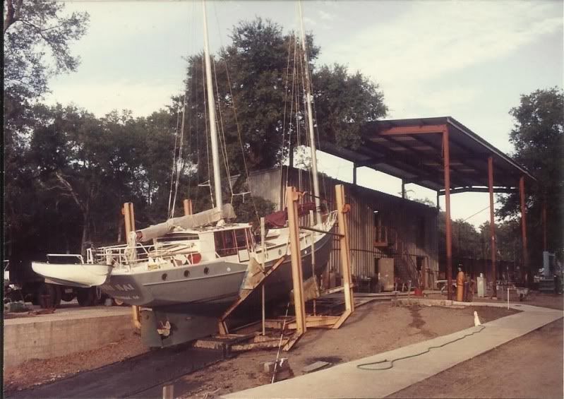
The junk-schooner rig is unstayed but I kept halyards and spares (for sails and flags) tied off to the lifeline stanchions. In heavy conditions I would rig one of them as a running back stay, tied off to a strong point near deck level.The "Cosmos Mariner,"My Goat Island Skiff
http://s176.photobucket.com/albums/w168/MiddleAgesMan/
Starting the Simmons Sea Skiff 18
http://www.flickr.com/photos/37973275@N03/
-
31st January 2012, 11:45 AM #40
Happily receives emails.
- Join Date
- Jul 2005
- Location
- 'Delaide, Australia
- Age
- 65
- Posts
- 8,138
It is always amazing to see what other people have done!
Wow MAM, wow!
MIK
-
2nd February 2012, 07:01 AM #41
SENIOR MEMBER
- Join Date
- Sep 2007
- Location
- Savannah GA USA
- Posts
- 583
As soon as my son gets it scanned I'll have one of her under sail. I hope it will be OK to take a slight detour with this thread.
BTW--I was using a wide angle lens to get the whole boat on the rail which caused the illusion that the foremast is smaller than the main. They were both 8 inch OD, cut from 45 foot poles; the main was 44' and was stepped on the keel just in front of the engine. The fore was cut to 39' and was stepped just ahead of the v-berth in the anchor rode locker. The main had about 4 1/2 feet of bury, the fore, 4.The "Cosmos Mariner,"My Goat Island Skiff
http://s176.photobucket.com/albums/w168/MiddleAgesMan/
Starting the Simmons Sea Skiff 18
http://www.flickr.com/photos/37973275@N03/
-
2nd February 2012, 10:54 AM #42
Happily receives emails.
- Join Date
- Jul 2005
- Location
- 'Delaide, Australia
- Age
- 65
- Posts
- 8,138
Howdy,
I've always liked when threads head off into other fertile grounds .. so a bit more is great MAM!
MIK
-
5th March 2012, 03:29 AM #43
SENIOR MEMBER
- Join Date
- Sep 2007
- Location
- Savannah GA USA
- Posts
- 583
Well, it only took about 35 days.
Here she is under full sail crossing the Bahama banks:
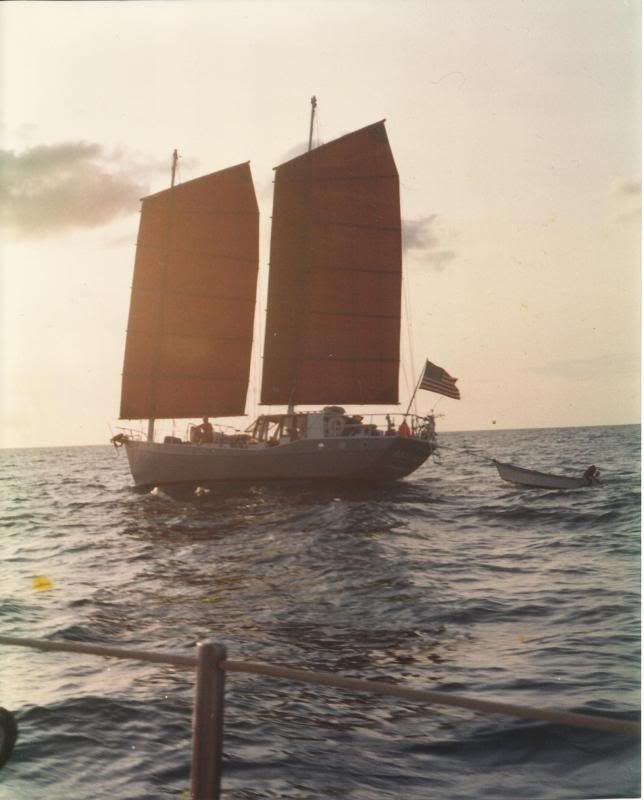
Underway in the ICW:
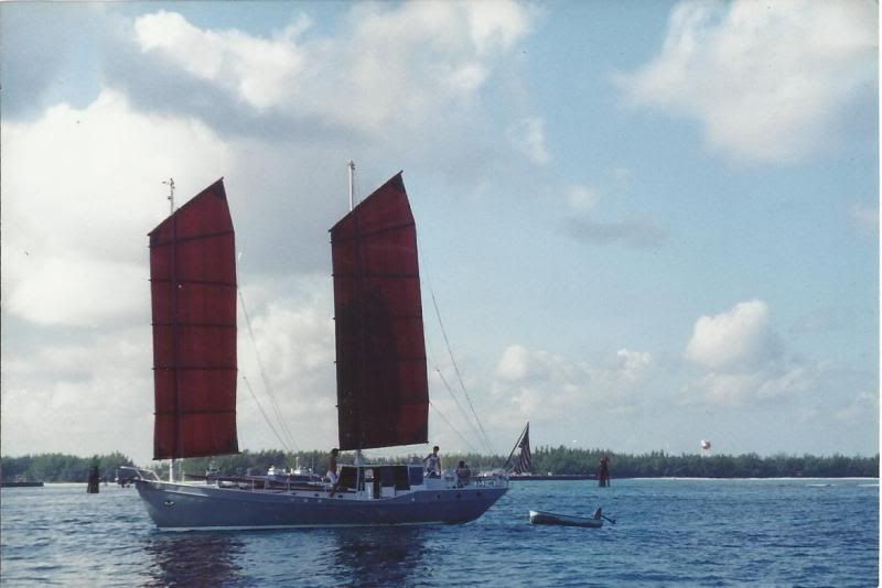
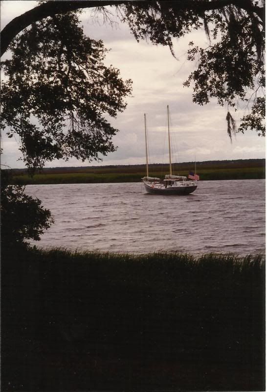
Some years later, here in coastal Georgia, while cruising with my second ex-wife:
 The "Cosmos Mariner,"My Goat Island Skiff
http://s176.photobucket.com/albums/w168/MiddleAgesMan/
Starting the Simmons Sea Skiff 18
http://www.flickr.com/photos/37973275@N03/
-
6th March 2012, 10:21 AM #44
Member
- Join Date
- Sep 2008
- Location
- Uppsala Sweden
- Posts
- 71
Colvin Gazelle?
Hi MAM,
That beautiful boat sure looks like one of Tom Colvin's designs, Gazelle? I used it as inspiration for my junk-rigged Wharram cat in the early 70s.
Peter
-
6th March 2012, 03:25 PM #45
SENIOR MEMBER
- Join Date
- Sep 2007
- Location
- Savannah GA USA
- Posts
- 583
Yep, a Gazelle with a pilot house I designed and a simplified junk rig, also of my design. It was a wonder boat.
The "Cosmos Mariner,"My Goat Island Skiff
http://s176.photobucket.com/albums/w168/MiddleAgesMan/
Starting the Simmons Sea Skiff 18
http://www.flickr.com/photos/37973275@N03/

 Reply With Quote

Similar Threads
-
flex drum
By big chisel in forum INTARSIAReplies: 2Last Post: 7th June 2011, 07:01 PM -
Mast making - Grain direction for mast staves
By m2c1Iw in forum Michael Storer Wooden Boat PlansReplies: 3Last Post: 4th February 2008, 10:44 PM -
Headstock flex
By Tiger in forum WOODTURNING - GENERALReplies: 29Last Post: 16th November 2006, 11:27 AM -
Mast timber question for the masters!
By Wild Dingo in forum BOAT BUILDING / REPAIRINGReplies: 13Last Post: 23rd July 2006, 02:36 AM -
3core flex
By Tonyz in forum NOTHING AT ALL TO DO WITH WOODWORKReplies: 26Last Post: 3rd January 2006, 08:00 AM
