

 Thanks: 0
 Likes: 0
 Needs Pictures: 0
 Picture(s) thanks: 0
Results 16 to 30 of 146
Thread: My Chinese CNC Saga (continued)
-
29th September 2011, 09:59 PM #16
 GOLD MEMBER


- Join Date
- May 2003
- Location
- Perth WA
- Posts
- 3,784

Hi Russell,
To put your mind at ease if it says embedded VFD inverter then you should be OK
I haven't come across that before but am no expert and probably no reason it can't be done.
Sorry if I raised your blood pressure.Cheers,
Rod
-
29th September 2011 09:59 PM # ADSGoogle Adsense Advertisement
- Join Date
- Always
- Location
- Advertising world
- Posts
- Many
-
1st October 2011, 08:38 AM #17
SENIOR MEMBER
- Join Date
- Sep 2008
- Location
- Maryvale, Queensland
- Posts
- 2,338
So I got the lid off the controller, and here's some updated pictures.
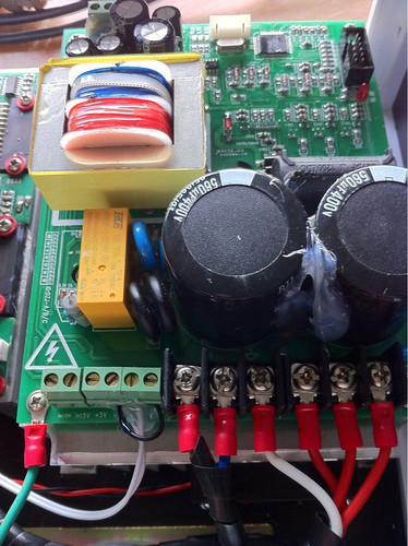
1. Controller internals
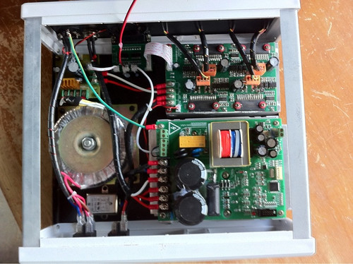
I can't tell whether any part of that is a VFD or not.
2. Close-ups of the water pump connector on the left. The spindle connector is on the right. The water pump connector has 1 black and 1 red cable connected to it.
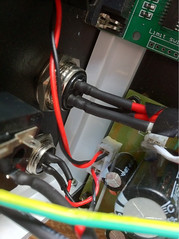
Red is positive, right?
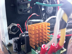
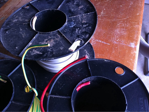
3. Cables I have
These are the leftover cables I have from having the shed wired. They're all multicore by the looks. This is too big to use for wiring the pump connectors together, isn't it?
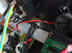
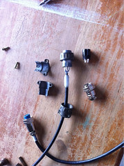
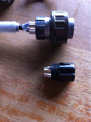
4. The spindle cable taken apart. It has a blue, black and brown cable, and 1 connection is left clear, even though there seems to be 4 cables connected inside the controller, so I'm not sure what the missing one might do?
Also, the correct replacement one is pulled apart next to it. The outside of the old and new one both have numbers 1 - 4 against each pin. The problem is, because the existing connector does not fit ont the controller plug, I'm not sure which pin on the controller would connect onto which wire in the cable, so I don't think I can just reconnect based on the numbering scheme on each of the connectors. You can see in the last picture on the right where the spindle cables connect to the motherboard - 3 red, 1 white. Any idea how I identify which of the controller pins should connect to which wire in the cable?
I must admit I'm sure where to go from here. Any pointers appreciated.
Thanks. Russell.Pen Affair Craft Supplies - Cheapest Pearl Ex & Pemo Polymer Clay in Australia
http://craftsupplies.penaffair.com
-
1st October 2011, 09:22 AM #18
GOLD MEMBER
- Join Date
- Apr 2002
- Location
- Margate Tasmania
- Posts
- 1,148
That is 240v cable and not suitable. Originally Posted by BoomerangInfo

Go to Dick Smith or Jaycar and get some low voltage multicore flex, similar size to what is used to feed to the socket.Kev
-
1st October 2011, 09:23 AM #19
GOLD MEMBER
- Join Date
- Jul 2006
- Location
- Port Huon
- Posts
- 2,685
Very different to my Chinese CNC controller which only contained a power supply and three separate motor controllers
My VFD was also a separate unit.Geoff
The view from home
-
1st October 2011, 10:18 AM #20
GOLD MEMBER
- Join Date
- Feb 2004
- Location
- Oxley, Brisbane
- Age
- 79
- Posts
- 3,041
Hi Russell Originally Posted by BoomerangInfo
Power up the control box and put a multimeter into the sockets for the pump. This will tell you which cable is positive and which is negative. (When the leads are correctly applied the display should not show a negative sign)
Are you sure that the pump does not have any markings on it to show the voltage and amperage or wattage? I thought that the laws in most countries required that nowadays.
Bob Willson
-
1st October 2011, 10:27 AM #21
GOLD MEMBER
- Join Date
- Feb 2004
- Location
- Oxley, Brisbane
- Age
- 79
- Posts
- 3,041
I think that the tubing for the pump would best be replaced with a type that doesn't kink. I recently installed my daughters refrigerator and it had a water supply tube from the mains to the ice maker inlet that was similar to flexible hydraulic tubing. I have seen this tubing used on water filters as well. Try your local plumbers supply. It is similar to this stuff.
Bob Willson
-
1st October 2011, 10:53 AM #22
GOLD MEMBER
- Join Date
- Jul 2010
- Location
- Shailer Park Brisbane Southside
- Age
- 62
- Posts
- 1,320
Check out the John Guestt range of fittings and tubing.
Cheers
Tony.
-
1st October 2011, 12:36 PM #23
GOLD MEMBER
- Join Date
- Feb 2004
- Location
- Oxley, Brisbane
- Age
- 79
- Posts
- 3,041
Yep, they are the ones.
Beautiful and easy to fit and maintain. Just screw in the fitting, cut the pipe to length and push the end of the pipe into the fitting. Done
Bob Willson
-
1st October 2011, 07:46 PM #24
SENIOR MEMBER
- Join Date
- Feb 2008
- Location
- Australia
- Posts
- 988
I'd advise against wiring up the spindle yourself as its 240V, its probably best to get a sparky in to wire it up thats if he can, or even buying a HY unit from ebay where most of the users here have used and can offer support, not only that but if you need to get a sparky in it should be a 5 minute job for him whereas with what you have now looks to be controlled by an output pin from the DB25 port which would require the control box to be connected to a pc and setup correctly.
White looks to be ground but the order of phases for the spindle I'd be taking a guess on, should be in the order they are placed on the PCB.
About the pump, the red wire will be your +24VDC (its running a transformer so my guess on the voltage could be incorrect but it looks like it has some Toshiba TB6560 drivers (or a similar model) which have a max of about 40VDC) and black being your negative, again this is assuming they stuck to standard colors which it looks like they have.
Personally I'd pull the VFD from the control box and sell it on ebay and buy a HY unit from ebay with the partial refund you received from paypal, should be like ~$150 shipped.
{EDIT}
Queensland has very strict rules for 240V wiring in that it's illegal for the average joe to wire up anything to do with 240V.
-
1st October 2011, 08:23 PM #25
SENIOR MEMBER
- Join Date
- Sep 2008
- Location
- Maryvale, Queensland
- Posts
- 2,338
Well, I love my little country town, but sometimes it has it's problems. neither Dick Smith nor the authorised Jaycar reseller have cable or any parts for DIY electronics. Looks like I'll have to shop online. Originally Posted by KevM
As for pulling the VFD from the control box, where would I start with that? Would anyone even buy what was pulled out? Looking at the VFD's on eBay, how do you get the input signal into them? That would also mean that none of the cables I have are correct. I'd basically be throwing out all the electronics I have and starting again, wouldn't I? Pen Affair Craft Supplies - Cheapest Pearl Ex & Pemo Polymer Clay in Australia
http://craftsupplies.penaffair.com
-
1st October 2011, 08:54 PM #26
SENIOR MEMBER
- Join Date
- Feb 2008
- Location
- Australia
- Posts
- 988
I was more thinking of it as a standalone unit, you would have to manually push run to turn the spindle on before you want to cut anything, all you'd need would be wire and the spindle plug. You could then later on upgrade to run it from mach 3 but I was just thinking of the easiest method to get things rolling. Originally Posted by BoomerangInfo
-
1st October 2011, 09:42 PM #27
SENIOR MEMBER
- Join Date
- Sep 2008
- Location
- Maryvale, Queensland
- Posts
- 2,338
Oh I see, just in effect replacing the power to the spindle with an external plug via the new VFD? The spindle speed would have to be set manually each time as well then, given the current unit controls that as well? So I wouldn't actually have to change the existing controller, I'd just be plugging the spindle into something else. That'd then need my current cable plug changed to the VFD power plug instead? Originally Posted by Ch4iS
Sorry if I'm a bit confused.
Russell.Pen Affair Craft Supplies - Cheapest Pearl Ex & Pemo Polymer Clay in Australia
http://craftsupplies.penaffair.com
-
1st October 2011, 10:14 PM #28
SENIOR MEMBER
- Join Date
- Feb 2008
- Location
- Australia
- Posts
- 988
The VFD has screw terminals it does not rely on any specific plug, so you will only need the plug that goes into the spindle. You'll need to wire up 240V to the VFD and then the 4 wires to the spindle and you'll be right to go after its programmed. Originally Posted by BoomerangInfo
If you control the VFD manually once setup all you do is push run to start the spindle, to change the speed you turn the little knob on the front.
One thing I have not done is program a VFD (Its always been setup from factory for me) but there is a thread here on WWF with guides ect. and troubleshooting which should make it easy to setup.
-
1st October 2011, 11:06 PM #29
GOLD MEMBER
- Join Date
- Feb 2004
- Location
- Oxley, Brisbane
- Age
- 79
- Posts
- 3,041
What little knob on the front? Originally Posted by Ch4iS
Bob Willson
-
1st October 2011, 11:18 PM #30
SENIOR MEMBER
- Join Date
- Feb 2008
- Location
- Australia
- Posts
- 988
Originally Posted by Bob Willson
Hmm. your right I'm so use to seeing a knob there.
Is it all electronic on the HY units? (Up and down arrows to change speed/frequency?) I wonder what brand I was using some time ago then.

 Reply With Quote


Similar Threads
-
Compond and mitre continued....
By jof062 in forum HAND TOOLS - POWEREDReplies: 4Last Post: 28th November 2009, 10:17 PM -
Hoop Pine continued
By cedar n silky in forum WOODTURNING - GENERALReplies: 15Last Post: 26th May 2007, 08:47 AM -
Money Box Continued
By Phil Spencer in forum WOODWORK PICSReplies: 4Last Post: 7th November 2006, 02:21 AM -
silky burl continued
By cedar n silky in forum WOODTURNING - GENERALReplies: 0Last Post: 28th October 2006, 10:24 PM -
Chook's thicknessing problems (continued...)
By chook in forum HAND TOOLS - POWEREDReplies: 4Last Post: 1st January 2005, 09:37 PM
