

 Thanks: 0
 Likes: 0
 Needs Pictures: 0
 Picture(s) thanks: 0
Results 1 to 15 of 21
Thread: lithograph engraving
-
2nd April 2012, 06:16 PM #1
 SENIOR MEMBER


- Join Date
- Dec 2004
- Location
- Up North
- Posts
- 1,799
 lithograph engraving
Where in OZ will I be able to get materials for lithograph engraving?
They mention Corian in the States but I have never seen it here.
Mind you I am far away from the big smoke
Cheers
WolffieEvery day is better than yesterday
Cheers
SAISAY
-
2nd April 2012 06:16 PM # ADSGoogle Adsense Advertisement
- Join Date
- Always
- Location
- Advertising world
- Posts
- Many
-
2nd April 2012, 06:54 PM #2
SENIOR MEMBER
- Join Date
- Nov 2006
- Location
- Darwin HowardSprings
- Age
- 52
- Posts
- 1,197

saw some scratching burs on ebay under CNC , what plate ? sliver plates might be hard find , but for copper just use circuit board ( copper backed by fibre glass , expensive in large sheets ) rub in some black paint and polish
 how come a 10mm peg dont fit in a 10mm hole
-
3rd April 2012, 06:48 AM #3
GOLD MEMBER

- Join Date
- Apr 2011
- Location
- McBride BC Canada
- Posts
- 3,543
Besides the copper-clad PC board, Plexiglas/Lucite/Perspex is an option.
I'm (very slowly) carving into flat 25mm stone slabs that were scraps from a stone cutting
operation to make stone kitchen countertops. I want to make some prints from that.
The stone is just soft enough that I can carve into it with an OLFA utility knife, the kind with the break-away blade sections.
A lot of the pieces are no more than 15 x 20cm but I did score a few 20 x 30cm.
I lapped one against another with water and extremely fine sand to get rid of the diamond rope saw marks. Worked rather well. I can see now that the white smudgy things are actually fossils!
All that stuff is currently still buried in 2m snow banks from the winter storms. Maybe another month, I'll find them.
-
3rd April 2012, 09:23 AM #4
Senior Member
- Join Date
- May 2009
- Location
- Gosford,NSW
- Posts
- 135
Hi Wolffie
Do you mean litho graph or litho phane? Corian is more related to the latter and copper plate, the former
Corain and similar solid surface materials can be found at kitchen bench mamufactuers.... sinks need cutouts so decent offcuts are usually available. For metal plates I'd search out a local offset printer and see if you can score some blanks.
Cheers
Mark
-
4th April 2012, 07:51 AM #5
SENIOR MEMBER
- Join Date
- Dec 2004
- Location
- Up North
- Posts
- 1,799
Sorry, I meant lithopane, the kind where you can see the design when you put a light behind it. Originally Posted by mhasting2004

Like this
Cheers
WolffieEvery day is better than yesterday
Cheers
SAISAY
-
4th April 2012, 08:47 AM #6
Senior Member
- Join Date
- May 2009
- Location
- Gosford,NSW
- Posts
- 135
Yeah I thought that was what you meant. I've tried Corian and to be honest was not overly impressed with the quality of the end result. Cuts beautifully and can hold fine detail but the stuff I had was too translucient for a given thickness so it meant the litho needed to be very deep.
The trick with these is to find a material with the following characteristics
- cuts well
- holds fine detail
- thin (less work, faster cutting and sharper detail)
- uniform thickness
- opaqueness gradiant that allows for bright whites in the thin parts while still having enough mechaical strength and dark enough in the thick areas to offer a decent gray scale. Note the gradient of Corian I tried was quite shallow so to get a decent greyscale range required a thick (12mm or more) piece. Too steep and it becomes unworkable as the variances in depth become miniscule.
Ive had very good results cutting melimine like you find in picnic plates but its rarely flat and uniform but is unreal a holding detail and very thin. If I could find sheets on that I'd be very happy.
My advice woul;d be to go down to the local hardware or $ shop with a strong flashlight and experiment. Materials that you can just see a shadow thru are possible candidates
Cheers
Mark
-
4th April 2012, 02:45 PM #7
SENIOR MEMBER
- Join Date
- Dec 2004
- Location
- Up North
- Posts
- 1,799
Mark
I have some 2-3 mm pieces of white, black and see-through smoky grey perspex. I also have some in 5 mm.
Would you think that would be useful?
I have a lovely perspex sign manufacturer in Cairns where I can get that from.
Cheers
WolffieEvery day is better than yesterday
Cheers
SAISAY
-
4th April 2012, 03:18 PM #8
SENIOR MEMBER
- Join Date
- Dec 2004
- Location
- Up North
- Posts
- 1,799
I just found a couple of pieces of the stuff they make breadboards from except it is smooth on both sides.
Have no idea what it is called but it appears to have the qualities you were mentioning.
Will give it a try when my machine arrives at the end of the month.
Cheers
WolffieEvery day is better than yesterday
Cheers
SAISAY
-
4th April 2012, 03:56 PM #9
Senior Member
- Join Date
- May 2009
- Location
- Gosford,NSW
- Posts
- 135
I've tried perspex but with the cutters I have (basic router style) it tended to reweld quite a bit. Corian and Melamine great as it comes off as a powder, PVC is ok as long as your bits are sharp but can be a bit furry once cut but a easy trick is to scrub the finished piece with some soap water and stainless brillo pad.
My advice is suck it and see... so to speak. Mileage will vary depending on cut speeds style of cutter etc etc.
I'll give you one more trick... if you are cutting thin materials, cut a 0.1mm deep frame around your actual litho first and put a pause or tool change in your program prior to the actual image code. This is so you can be sure that the material is setup correctly (flat and at the right hieght) b efore commiting to an hour plus cut time.
Nothing sucks worse than cutting a pipe for 2 hours only to have it punch thru near the end.
-
5th April 2012, 09:03 AM #10
Intermediate Member
- Join Date
- Jan 2009
- Location
- Gundaroo
- Posts
- 41
Hi Wolffie,
Only relatively new to litho's myself but have had good success with corian. See if you can pick up some off cuts from a kitchen bench top supplier. Had a hardware store in Sydney selling new old stock of vanity tops for $5. It was a 500km round trip but well worth the $100 I spent on 20 tops.Takes a bit to reclaim the corian, but probably $250 to $300 worth of corian in each top.
My 2c worth
Cheers
Kim
-
6th April 2012, 09:50 PM #11
Senior Member
- Join Date
- Jan 2009
- Location
- near Cooyar, (Toowoomba-ish), Qld
- Age
- 59
- Posts
- 221
Corian?
Benchtop material?
Cutting boards? (that's polyethylene, generally)
We've done a heap of lithophanes using standard opal acrylic sheet.
Opal = semi-translucent white
Acrylic sheet = perspex.
You can also use polycarbonate if you can find it. It's a more flexible & more 'bullet-proof' (less shatterable) product than standard acrylic.
I've found 6mm stuff to be not as good as 4.5mm or even 3mm stuff.
The deeper you need to go, I found, the coarser the detail ended up becoming.
The nicest ones we did in the 3mm stuff, making black at about 0.1mm deep (barely a scratch) and white at about 2.6-2.7mm deep (almost all the way through)
Play around in photoshop, and add a nice black border feathered a bit-to give you good gentle edges.
The nicest one we did was using a 3/64" ballnose cutter with about 85% step (i.e. 15% of cutter diameter of new material cut per pass)
We generally rough them out with say a 1/8" ballnose or sometimes a 1/4" BN first, at about 0.33-0.5mm above proper height, and about 50% step over. That can take 5-10 mins, then the fine file can take up to a couple of hours, depending on the size of the job.
I'll admit, we are signwriters, so have a bit of the acrylic sheet spare from old broken lightboxe faces etc, but it is easy enough to get hold of, normally.
-
6th April 2012, 10:19 PM #12
Senior Member
- Join Date
- Jan 2009
- Location
- near Cooyar, (Toowoomba-ish), Qld
- Age
- 59
- Posts
- 221
Here is the first lithophane we ever did, and if you want, I can add a rough writeup I did for a national sign magazine after doing a few more.
I made a candle-lit box with four of them a year or so later, for my in-laws for Christmas.
The steps followed, in order, (including errors), for that first lithophane were:
1. decide to do it- i.e. something, and to finish it.
2. find a nice photo, preferably with a good range of grey shades, and a few hard edges.
3. open the photo in Photoshop or other image editor, and adjust the levels, or amount of black or white, to achieve a nice scale or range from light to dark. You don't want it to mostly all be light, or all dark, for instance.
4. size it to suit the material thay you've just found. I had some samples of this stuff from a Letterheads event in Australia. It's a plexiglass/perspex/acrylic type of product made by Bayer. It's technically called polycarbonate. I had a few sheets of 21 x 29 cm x 3mm thick (just under 1/8", and A4 page sized).
5. convert the picture to greyscale- this should have been done earlier actually. When finished, sharpen the picture a little, and save it as a jpg.
6.I screwed the sheeting to the MDF spoilboard, with drywall screws around each edge- just the countersunk heads hold it down, and the shank prevents movement.
7. I put a 1/8" ballnose tungsten endmill in the router, for a roughing cut.
8. Back to the software- with enroute, you define the plate- in this case 210 x 280 x 3 mm, and with a blank plate you import the jpg file of the photo.
9. to make it a relief, you draw a rectangle the size it's going to be, allowing for a suitable margin (about 2" on all sides here). Then convert that 2D rectangle to a 3D relief with the 'make relief' button- give it a height of zero, a flat top, and a resolution of 100 dpi. You now have a photo-sized 3D relief of zero height/thickness.
Centre it where you wish, allowing for the margins to be equal, or a whisker more margin underneath it, for a nice appearance.
I drag guidelines it to each edge to help. Othertimes, I'll draw a big box the size of the whole plate, and select all, and centre all, then delete the big box. Other times I'll create guidelines in the dead centre horizontally & vertically, and use those to align the relief's 'handles' with.
11. Position the photo over the relief, and select the 'apply bitmap to relief' button.
It'll ask you which relief to apply it to, and what overall thickness it's to become. I chose 2.35mm- that'll allow for 0.7 mm of material in the thinnest parts, plus allow for inaccuracies in bed thickness.
10. Take the photo, and OOPS- the relief is going to be high on the white bits, and deep in the blacks- and that's the opposite of the effect you want with a lithophane, so quickly reopen your image editing program and open the last saved picture and invert it to make it a negative and resave it.
11. Go back to the relief and use control-Z or undo, or the 'delete relief' button, and redraw your flat rectangle & make it a relief of zero height again- it's all good practice!
Now you're glad you drew in those guidelines- it's easy to realign the new relief where you want it on the material plate, if the 'snap to guidelines' option is turned on.
12. Import the negative of the photo, position it over the relief, and choose the 'apply bitmap to relief' button once again, tell it which relief, and set the thickness it's to become. Press 'enter' or 'apply' to get it all done.
13. The relief will be sitting in the air above the material plate, so use the button which says 'align all reliefs to the top of the plate'. This pushes it all down to sit just touching the inside top surface of the material, and leaves a skinny bit of untouched material between the bottom of where the lithophane will end, and the bottom of the material.
14. Save it. The you need to apply a toolpath, Enroute does all the 'post processing' to create the G code, as well as being a design program. So, select the relief, and I chose 'hatch fill' of the toolpath options. That opens a tool selecting menu, where you set the 1/8" endmill, I chose the depth to be 2.35mm full depth of the file, but allow this tool to stay 0.8mm off the bottom of the cut. Overlap was set for 60%, and speeds were- well I tried 130mm/sec for X & Y, and 30 mm/sec for Z, but it trundled along quite slowly except where it wasn't changing height much. If I reset it to 80 mm/s X & Y, and 20mm/s for Z, it still went no more slowly & no faster. There's a limiting factor somewhere in Z that I'm not aware of. Y only moves a whisker per pass- just the 60% OF THE 1/8" TOOL DIAMETER oops sorry about the caps. X speeds along smartly when Z isn't changing. Must be somethng somewhere that needs editing- no idea where. (The Z axis servo did get awfully hot though, duting the 1/16" cuts-due to the delrin nut not being lubricated well. Fixed that by changing it to a ballnut & screwthread later.)
Anyhow, it took maybe 18-20 mins to rough it out with the 1/8" endmill after I'd exported the G-code & saved it.
15. I then edited the toolpath, to be run with a 1/16" diam ballnose endmill, at the same speed, and 66% pass overlap, and full 2.35mm depth, and checked it all by looking at the perspective view to ensure it was moving up and down, not just flat bottoming the whole picture out (yes, I did that with another file once, not a lithophane, but I ended up with a big oval empty space in a lovely bit of timber...) Actually you need to verify the toolpaths look right, back when you create them with the 1/8" ballmill in step 14.
16. Change cutters, put the 1/16" ballnose endmill in, sense the tool length, and start routing. It took about 1 3/4 hours to do the rest. We had a lightning strike in way out the distance which caused a flicker of mains power, the PC & the onboard computer in the router kept going, but the rotary 3-phase converter powering the spindle died. The cutter started to drag across the material- quick hit the emergency stop!
17. Restart the file- oh, no, not an hour and a quarter of waiting to catch up to where it left off...what other options are there...thinking thinking...
a. I tried this once- 'guillotine off' the part of the relief already done, using the 'subtract from relief' option after making a new relief as a box over the part you want removed- and export new toolpaths. Sounds great, but it made the toolpaths go at zero height (plate bottom) over the already cut stuff, ruining it, in a former attempt at being a genius, so that won't work.
b. similar idea- only ADD a flat topped box to the file, and merge the highest parts. That did work- it skipped quickly over the parts at high speed, taking about 15 mins to get to where we had to pick up from, saving an hour's wait.
c. Thinking later, in hindsight, I should have just rotated the piece (the relief)180 degrees, in the program, generated a new toolpath which now starts at what would have been the end, then rotate the piece/relief back 180 degrees to where it was, and export that toolpath to G-code. That would make the file start at the other end and work its way through up to where it ran out of juice the first time. You just stop it then, after they join up & overlap, hoping like mad that you didn't accidentally move the relief a mm of so in your rotating. (Hence using guides & the 'snap to' option)
Ordinarily, it'll rotate around the dead centre & rotate back without being displaced, so there's no problem, but it's easy to get carried away & accidentally move something a whisker. Be careful!
I have since learned you can 'mask off' areas you don't need to rerun, when this sort of thing happens.
18. In this case, I added a black outline and then a white outline to the original photo, before saving it. IN hindsight, I should have just created a single perimeter 'frame' and routed a groove in/around that, as an entirely separate 2D offset toolpath, once the lithophane was done. I did that afterwards anyway, to neaten up the edges of the deep 'white' groove previously created.
19. Decide on the text, the font & size, and I appllied it as a 2.5D vee-grooved or engraved toolpath with a conic or 45 degree engraving tool. It was one of those tngsten engraving cutters which is sharpened by being half flat across the diameter. It wasn't a good choice of tool. It was brand new, but the plasticky bits just reglued themselves to the material after being cut. Maybe I should have run the router faster & the spindle more slowly...? So, I ran the text cutting G-code a second time, and that cleaned out the gunk better, and a nail-scrubbing brush followed by an exacto knife blade dragged on edge did the rest of the furry bits.
20. Unscrew the material from the router bed, vacuum up any scraps of plastic, and go outside to look at it with the sky as the background. Congratulate yourself that the tool didn't go right through to the spoilboard in any places, and that the 2nd pass to finish it after the power failure linked up almost imperceptibly with the first part.
The effect is that the material, opal or milky-white ( I've just remembered, I think it was called Makrolon, or something like that)- the material is thinnest where the picture is whitest- allowing the most light through from the back. The material is thickest where the picture is blackest, filtering out most of the light. In between are lovely gradients of appropriate grey.
It looks like magic comparing the fuzzy queer looking front, with the proper image when back-lit.
This was the first time I tried to do this so I'm no expert. I did consider starting with a greater overlap- say 85% per pass with the 1/16 cutter, but it would have taken forever, and the detail just wasn't in the original photo to be preserved with a 1/16" cutter, so 66% was quite OK in my mind. Maybe 50% would have been tolerable also, I don't know.
Our router sometimes doesn't do its heights properly. I have no idea why. When I ran the first file, the 1/8" one, I told the machine that the material was 3.6mm thick above the bed, not 3mm, just to see how the paths started off- I didn't want it scratching too deep in places where I had no grace. After it looked OK, I restarted the file with the overall thickness set at 3.15mm, even though the stuff was 3.0 thick. I left the file set at 3.15, and I'm glad I did.
Another piece of advice- use a clean sharp (new) 1/16" endmill to cut the plastic stuff, not an old worn dirty one.
I tried a second file a day later, making it from an oval relief. It would have worked but the storm brewing did it's trick with the power again when I wasn't babysitting the machine, and it started to gouge the piece where I didn't want it to, onluy it didn't lift at all, so we had some zero height gouges. I tried to rerun the file later, but in my imnpatientness (?) to save a lot of time, I ended up toolpathing the wrong bits, and gouging away the background that was supposed to stay untouched. (In haste, I didn't check the toolpaths in perspective view before exporting them to G-code, you see... Pride comes before fall, or several falls, and very much so...!
So...I hope that helps, or at least, is somewhat entertaining!
I am sure there would be equivalent processes in other software.
P.S. we've propbably done 25-30 lithophanes now-all good fun & different experiences in each one. The thicker the material we started with, generally the less nice the finished image was. Others might disagree, but that's what we've found.
I'll try & find a pic of the candle-lit box...
-
6th April 2012, 10:37 PM #13
Senior Member
- Join Date
- Jan 2009
- Location
- near Cooyar, (Toowoomba-ish), Qld
- Age
- 59
- Posts
- 221
Here it is:
Two days before Christmas, I still did not have any present for my parents-in-law, just some ideas.
I did this as 'a quickie' on Christmas Eve, to be a present for them. It took all of 15 hours I think...you don't seem to realise where the time goes!
This is the almost finished product, before I'd sanded the timber & oiled it:
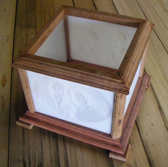
This is the view with a candle inside. It has a circular hole in the bottom so it can be lowered over a candle-unfortunately we had only a short dim one for this photo:

and turning it round a bit is a pic of my wife Joan and three of her siblings at the beach as toddlers in about 1959-60:

The other three photos were of my wife's parents on their wedding day in 1954, her Dad's parents on their wedding day in the 1920s, and her Dad with his almost 95 year old brother taken last year.
They're routed in 4.5mm 'opal' or translucent lexan/perspex/acrylic, scrap from another job I did.
The timber has a story also-I cut it down from a tree that used to be in their garden back when my wife & I were first engaged, and from some other pieces of timber left over from the factory her Dad managed all his life, before the new owners shut it down.
The base was a bit of mahogany I got from goodness-knows-where which I'd been keeping 'for something nice'.
It took a while to 'design' which (hand) router bits to use to make the mouldings with rebates for the lithophanes. I was intending it to have a bit of a japanese pagoda look about it.
It was received very well, and actually doesn't need a candle, but the window light comes in the top and lights it well enough during the day.
Here's another we did as a wedding present for some freinds:

The heart part rotates. That was a feature we built into it after an unexpected stuff-up!

Hope that all helps- have fun with yours anyway, and don't forget to post some photos here!
-
7th April 2012, 08:23 AM #14
Senior Member
- Join Date
- May 2009
- Location
- Gosford,NSW
- Posts
- 135
Nice work Stewey
Its great to hear others making similar stuffups but as you say sometimes this leads to an interesting "feature" like the heart cut out.
I concurr that better results are obtained with thinner materials ie the PVC pipe is only 1.6mm thick and the image depth is 1.4 .. the Melimine plates I used were even thinner at around 1mm and even better results due to the harder more opaque material.
I use the single pass method using a 45 degree router bit (would love to find an "O" flute cutter in a V bit... might need to make my own). The fine tip will give you incredible detail and a step over of up to 0.2 mm is ok and not perceptible.
I cut at 45 degrees to the horizontal which is a halftone printing trick as the most promenant colour (usually black) is at this angle to help hide it from the eye.. we humans pick up vertical and horizontal lines easily.
This method works because the image depth is so small and the gradiant from white to black caused by the V bit is very narrow. You do need a very accurate Z axis though.
As you say the limiting factor in the speed, or more to the point acceleration, is the Z axis movments and a trick in the Artcam software is to hit the smooth button a couple of times which removes some of the very fine detail but not so much that you would notice and makes for a much faster running file.
Your eye can fool you too into seeing more detail than is actually there when its a recognisable thing like a face.
The last pic you posted is a good example of what to look for in a material as you can see the shadows from the blind thru the material. I'd say that would be around the limit of translusense as it limits your black to white gradient... Note a Melimine plate is almost opaque before cutting and even PVC tube is unlikely to be that clear either. That is the test I was trying to describe... hold your test material up to the light and see if a shadow on the back is percerptible on the front.
Lithos are great gifts but also incredibly frustrating to make as you WILL stuff up at least one or two after investing heaps of time.
Cheers
-
7th April 2012, 09:15 AM #15
SENIOR MEMBER
- Join Date
- Dec 2004
- Location
- Up North
- Posts
- 1,799
Thank you to both Stewey and Mark.
I can't wait to get the machine installed and get started.
We are going up to Cairns in a couple of weeks so will try to get some supplies there.
I have already made up a few plans so have itchy fingers
Thanks again
WolffieEvery day is better than yesterday
Cheers
SAISAY


 Reply With Quote
Similar Threads
-
pen engraving
By stevemillar in forum WOODTURNING - PEN TURNINGReplies: 10Last Post: 28th October 2011, 01:42 AM -
pen engraving
By tweed woody in forum WOODTURNING - PEN TURNINGReplies: 2Last Post: 10th November 2010, 09:40 AM -
Saw Engraving
By Alex.R in forum HAND TOOLS - UNPOWEREDReplies: 11Last Post: 31st March 2010, 09:54 PM -
Engraving options
By Tiger in forum WOODTURNING - PEN TURNINGReplies: 10Last Post: 22nd February 2009, 05:56 PM -
engraving pens
By Rum Pig in forum WOODTURNING - GENERALReplies: 0Last Post: 1st August 2008, 01:51 PM
