

 Thanks: 0
 Likes: 0
 Needs Pictures: 0
 Picture(s) thanks: 0
Results 1 to 13 of 13
Thread: Glad to have my Hercus
-
2nd August 2010, 09:12 PM #1
 Fit to Machine


- Join Date
- May 2009
- Location
- Illawarra
- Posts
- 16
 Glad to have my Hercus
Hi All,
My missus recently had her sewing machine die on her. After pulling it apart I found that the plastic drive sprocket was chewed up. Not bad for a $500 Singer!. Couldn't get a replacement sprocket so I decided to make my own.
I was thinking I'd have trouble, as the sprocket is for a toothed belt, but I remembered my Dad telling me about the indexing attachment he'd made for the Hercus, and thought I'd have a go.
Ground up a tool for the teeth, and a tool for the keyway.
Have a look at the photo...
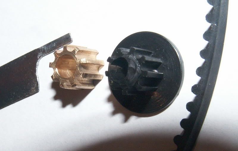
and then pick up a ruler and visualise this thing I've made....
it's 8mm OD. 4mm shaft. 2mm x 0.5mm key...... Jeez I hope it works.
-
2nd August 2010 09:12 PM # ADSGoogle Adsense Advertisement
- Join Date
- Always
- Location
- Advertising world
- Posts
- Many
-
3rd August 2010, 02:11 PM #2
Fixer and Mangler
- Join Date
- Apr 2004
- Location
- Melbourne
- Age
- 64
- Posts
- 250

How did you do it? ie was it in a lathe and moving the carriage to emulate a hand operated shaper or was it a milling operation with the blank held on an index-able arbour on the cross slide --- or was it not on a lathe?
I continue to be inspired by what can be achieved.
Thanks for sharing
Davidcheers
David
------------------------------------------------
A society grows great when old men plant trees whose shade theyll never sit in. (Greek proverb)
-
4th August 2010, 03:01 AM #3Dave J Guest
You did a good job on that, how did it go?
Dave
-
4th August 2010, 10:45 AM #4
Fit to Machine
- Join Date
- May 2009
- Location
- Illawarra
- Posts
- 16
The brass was held in the chuck. I ground a tool to 1.8mm round to make the grooves.
Yes, I used the carriage like a shaper.
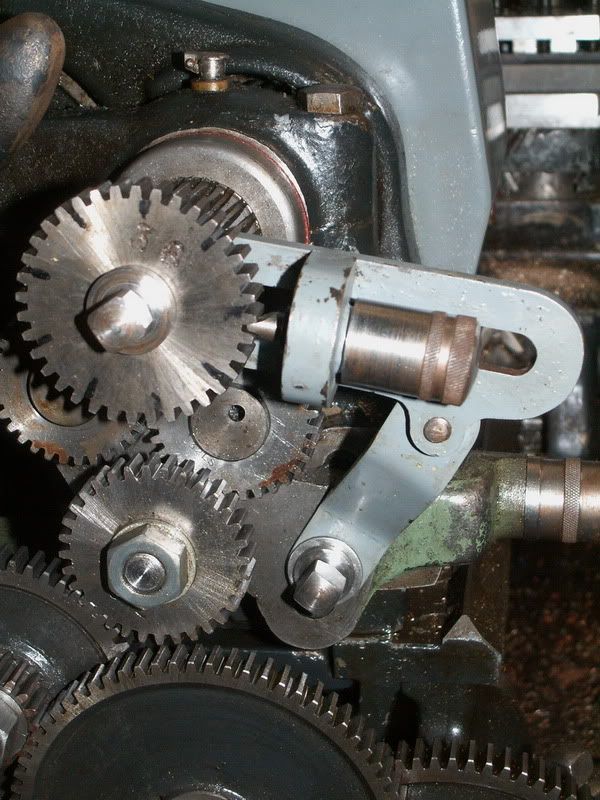
My Dad had made an indexing attachment for the spindle. It locks into the back of the spindle, and you just pick one of the leadscrew gears with the right number of teeth. It locks into the spindle as well and it has a spring loaded finger that locks into the teeth.
I haven't finished it yet. I'm still trying to fine tune the keyway. I tried a simlar thing to cut the keyway, but the bit of 1/8" HSS that I ground down was flexing. So I'm having to finish the keyway with a needle file.
-
4th August 2010, 02:46 PM #5
Fixer and Mangler
- Join Date
- Apr 2004
- Location
- Melbourne
- Age
- 64
- Posts
- 250
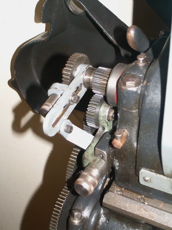
Would be interested to see how the indexing attachment fits and works.
On cutting an internal key-way: I had the same issue in my one attempt and like you got close enough that some fitting finished it. I was making a spacer for the change gears and needed a 1/8 key-way. I simply held a piece of 1/8 tool steel in the tool holder so it was parallel with the bore of the spacer. The tool wanted to either catch or bend away from the cut.
a discussion in these forums
https://www.woodworkforums.com/f65/su...19/#post498730
pointed me to a device that fits to the toolpost and uses a tool much as fitted in a boring bar.
SLOTTER
but there were other nifty ideas.
A small bore would be more challenging than my bigger effort.cheers
David
------------------------------------------------
A society grows great when old men plant trees whose shade theyll never sit in. (Greek proverb)
-
4th August 2010, 08:49 PM #6
Fit to Machine
- Join Date
- May 2009
- Location
- Illawarra
- Posts
- 16
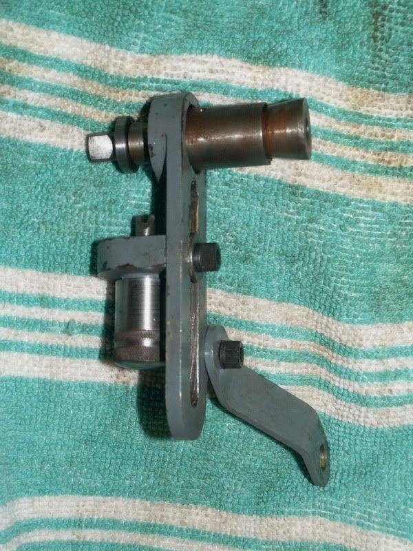
This is the indexing attachment for my lathe. My Dad made it, I'm not sure if he got the idea from a model engineer mag or thunk it up himself.
-
5th August 2010, 12:06 PM #7
Fixer and Mangler
- Join Date
- Apr 2004
- Location
- Melbourne
- Age
- 64
- Posts
- 250
Thank you.
In the first photo, I assume the piece that goes inside the spindle, with the wedge inside it, has a couple of slots cut to allow it to expand - like an old fashioned bike head stem -- or is it all a nice fit so the stretch of the metal is enough?
I like the simplicity of the design and no change to lathe
cheers
David
------------------------------------------------
A society grows great when old men plant trees whose shade theyll never sit in. (Greek proverb)
-
5th August 2010, 12:23 PM #8
Senior Member
- Join Date
- Mar 2007
- Location
- Canberra
- Age
- 68
- Posts
- 181
BEE55T. I like the idea of that indexing attachment. I think you've just created me some more work. I want one of those.
Can you tell me if the shaft that holds the gear and goes into the spindle is held captive (in a bearing) at the support arm or is just floating free. Looking at the pics I can't see any paint missing where the spindle would scrape against the support arm if it was floating free. In the first pic it also looks like there is some clearance around the shaft.Peter
-
5th August 2010, 08:47 PM #9
Mechanical Butcher
- Join Date
- Oct 2004
- Location
- Southern Highlands NSW
- Posts
- 920
Whatever, it's a nice design, well made. Originally Posted by BEE55T

Jordan
-
5th August 2010, 10:17 PM #10
Fit to Machine
- Join Date
- May 2009
- Location
- Illawarra
- Posts
- 16
Yes, the sleeve that fits into the spindle is spit. In the photo you can just see the keyhole type slot at the top left.
And the support arm is a fairly neat fit over the spindle lock section.
Would people be interested in a full drawing/write up?
I can pull it apart and measure it up if you'd all like.
-
5th August 2010, 10:23 PM #11
Mechanical Butcher
- Join Date
- Oct 2004
- Location
- Southern Highlands NSW
- Posts
- 920
Ok !
-
5th August 2010, 10:31 PM #12
Senior Member
- Join Date
- Mar 2007
- Location
- Canberra
- Age
- 68
- Posts
- 181
Yes please. I started drawing one up tonight to figure out how to make it but that would save some of my old brain cells. Originally Posted by BEE55T
Peter
-
6th August 2010, 10:46 PM #13
Fit to Machine
- Join Date
- May 2009
- Location
- Illawarra
- Posts
- 16
I've started sketching it all up, just got to figure it out myself. Will post up a new thread when I get it sorted.


Similar Threads
-
Glad to be here
By SCR0LL3R in forum G'day mate - THE WELCOME WAGON -Introduce yourselfReplies: 4Last Post: 24th May 2010, 08:13 PM -
Who Else is glad...
By lubbing5cherubs in forum WOOD WHISPERING WOMENReplies: 10Last Post: 15th January 2008, 09:20 PM -
Hallo, glad you are here , so I can be too
By Manuka Jock in forum WOODTURNING - GENERALReplies: 36Last Post: 5th July 2007, 12:03 AM -
Glad it's not an aussie cat
By Toolin Around in forum NOTHING AT ALL TO DO WITH WOODWORKReplies: 8Last Post: 27th January 2007, 09:57 PM -
Glad to be with you
By La truciolara in forum WOODTURNING - ORNAMENTAL TURNINGReplies: 4Last Post: 27th May 2005, 06:18 PM
