

 Thanks:
  Likes:
  Needs Pictures: 0
 Picture(s) thanks:
Results 16 to 30 of 110
Thread: Automated Router table
-
13th March 2019, 09:04 AM #16
 Member


- Join Date
- May 2012
- Location
- brisbane
- Posts
- 87

mee too
-
13th March 2019 09:04 AM # ADSGoogle Adsense Advertisement
- Join Date
- Always
- Location
- Advertising world
- Posts
- Many
-
13th March 2019, 09:23 AM #17
Supporting my wife's hobby.
- Join Date
- Nov 2013
- Location
- Caboolture QLD AU
- Posts
- 781
Hi Chris, actually I don't expect any real response to this thread, a lot if it is, after all, a recap of the current build and most of this has been posted before but scattered about in various threads.
In a way I'm glad, it has allowed me to get most of the basic information on the build in one place, I know there is not a lot of detail in these posts and once the main info is out the way I can elaborate as needed.
Most people are here for the love of woodworking, so technically difficult builds are not of interest for a lot of forum readers. I never intended to go to this level of automation with something as seemingly simple as a router table, however, and it's a big however - I didn't realise how often I bypassed the Router table because of the setup time needed to accurately rout even a simple job, that has completely changed, and with spiral up down bits I now look for every opportunity to use this table, it's just so fast and simple to use, there is no cleanup and no dust so I don't need a mask as there is zero affect on my hay fever / sinus problem with the Router Table.
I'm planning on doing some quality screen grabs of the controller screens and will attempt to capture a better video of the table in action.
You would have noticed that I used a thick table top for this table top rebuild, I only did that because I had a new spare top. A thinner top would be better as long as it is not prone to going out of shape and I think you started a thread for ideas for a thin top.
One of the nice things about this build is that the top supports nothing, no big heavy router hanging off of it and the hole in the top is a simple straight through cut that is relatively small compared to Top and to the way we normally butcher the Router top with a big router plate, Router and sometimes a lift, again all hanging off the table top with a huge chunk cut out in the center allowing it to flex over time in some cases.
Finally, the ability to simply lift the top off the table without touching a single screw or bolt is amazing in use. Every part of the internals are so simple to access when needed. I originally made the RH control unit (router Motor power control and NVR) removable as the table was screwed down, had the router attached to it and the whole thing was a pain to take off, that control unit can now be fixed in place and this again simplifies the build, that's the same with the LH control unit which holds the Stepper Motor Power supply and the two small stepper driver modules, all leading to a really neat and simplified design for this type of RT.(1) Our small workshop layout __ (2) Bandsaw circle cutting jig __ (3) Spindle sander modifications __ (4) Dust Sensor
(5) Router table redesigned ____ (6) DC and where it all began __ (7) Bandsaw dust extraction build
-
13th March 2019, 09:32 AM #18
Wood Hacker
- Join Date
- Aug 2009
- Location
- East Warburton, Vic
- Posts
- 1,604
Come up a treat Mike, just one question, what material is the table top?
Cheers
DJ
-
13th March 2019, 09:47 AM #19
Supporting my wife's hobby.
- Join Date
- Nov 2013
- Location
- Caboolture QLD AU
- Posts
- 781
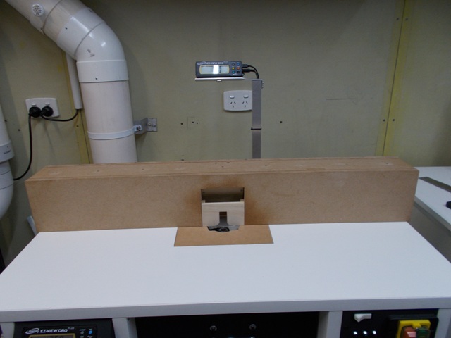
Thanks, the top is a thinner version of the typical thick kitchen counter top - laminated compressed particle board. I bought 8 panels this size for around $12.00 each a few years back at a closing down sale, they were sold as wide span heavy duty (no sag) exposed shelving supported at each end by a separate almost hidden thin metal angle mounting rail.
Mike.(1) Our small workshop layout __ (2) Bandsaw circle cutting jig __ (3) Spindle sander modifications __ (4) Dust Sensor
(5) Router table redesigned ____ (6) DC and where it all began __ (7) Bandsaw dust extraction build
-
13th March 2019, 01:27 PM #20
Supporting my wife's hobby.
- Join Date
- Nov 2013
- Location
- Caboolture QLD AU
- Posts
- 781
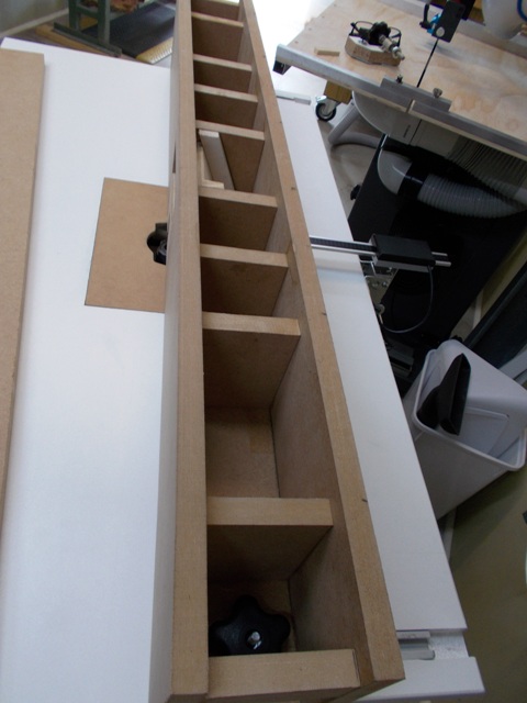
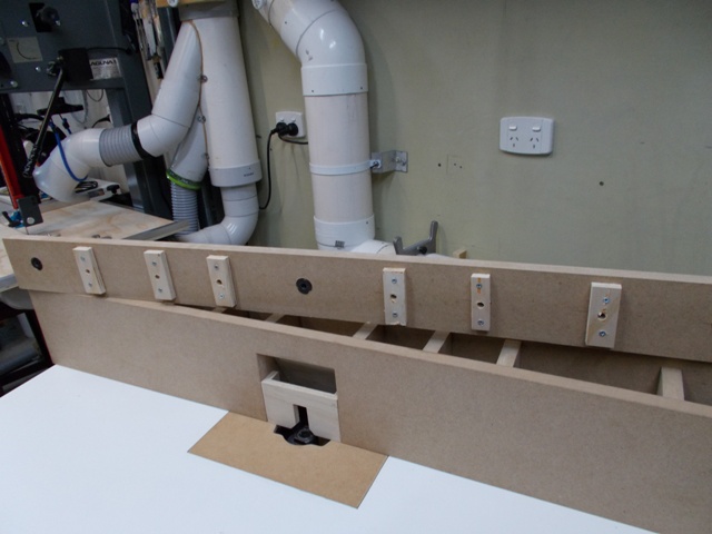
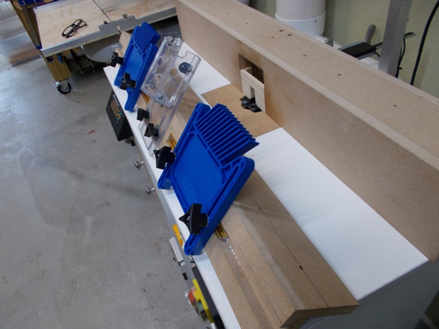
Again I'm adding this from another thread on the previous design, this time on making the Fence, I have an addition to the Fence on the way and hopefully this post will tie it all together in one thread.
I wanted a strong basic SUB Fence, one that allowed me to swap the top fence configuration for different jobs.
 .
. 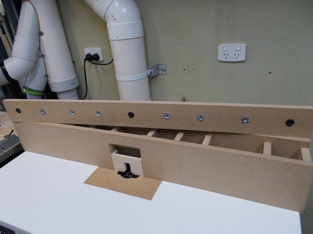
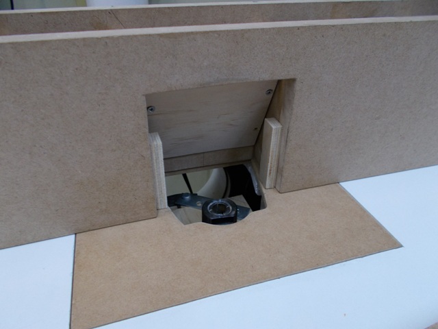
Ply strips screwed over the T-nuts, obviously to make sure that they never fall out as this part is glued in to complete the fence. Followed up by a view of the Fence "through table" dust extraction.
 .
. 
Basic Fence ready for an Extension top, this is shown on the old version of the Router Table.
Below: This top extension is the one you see in most of the photos. Followed by the Extension fitted to the Fence on the current Router table, takes all of 20 seconds to remove or install.
 .
. 
My reason for including the Fence build here? The next Top Extension will be a light weight Right angle Jig running from a 12mm Linear Rail and two Bearing block that sit on a flat base attached to the top of the Basic Fence. Strong and as smooth as silk gliding across the Table and always registered 90 deg to the Fence under all conditions with zero play, virtue of wide spaced roller bearing rail blocks and a linear rail. The same blocks but shorter rails are used on each side of the automated Fence system.(1) Our small workshop layout __ (2) Bandsaw circle cutting jig __ (3) Spindle sander modifications __ (4) Dust Sensor
(5) Router table redesigned ____ (6) DC and where it all began __ (7) Bandsaw dust extraction build
-
13th March 2019, 03:39 PM #21
GOLD MEMBER

- Join Date
- May 2013
- Location
- Rockhampton QLD
- Age
- 68
- Posts
- 2,339
There�s a lot of thought been put into this. Thanks for showing us.
Ross
-
13th March 2019, 07:43 PM #22
Supporting my wife's hobby.
- Join Date
- Nov 2013
- Location
- Caboolture QLD AU
- Posts
- 781
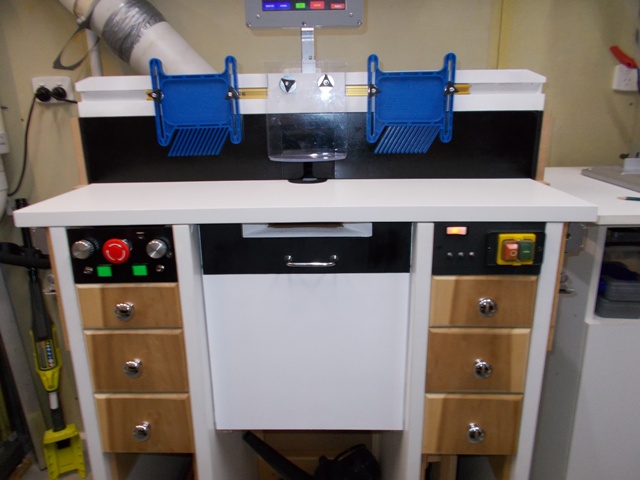
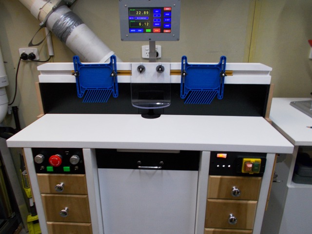
A bit of decorating.
Finally colour matched the new Router Lift cabinet door on this build. The below table dust extraction intake port is now easily seen, although the top half is hidden under the table overhang.
BTW the Touch Screen controller bracket is mounted to the back of the fence, obviously the controller travels with the fence.
 .
(1) Our small workshop layout __ (2) Bandsaw circle cutting jig __ (3) Spindle sander modifications __ (4) Dust Sensor
.
(1) Our small workshop layout __ (2) Bandsaw circle cutting jig __ (3) Spindle sander modifications __ (4) Dust Sensor
(5) Router table redesigned ____ (6) DC and where it all began __ (7) Bandsaw dust extraction build
-
14th March 2019, 10:51 AM #23
Senior Member
- Join Date
- Mar 2012
- Location
- South Gippsland
- Age
- 58
- Posts
- 103
I'm really keen to build something like this, so thanks for sharing this amazing and thoughtful build. It's on the list, but a long way down as the to do list is sooo long.
-
14th March 2019, 08:54 PM #24
Supporting my wife's hobby.
- Join Date
- Nov 2013
- Location
- Caboolture QLD AU
- Posts
- 781
Some Menus for the Automated Router Table: These captures are memory grabs from the display buffer in the controller, the image is actually twice as good when viewed on screen, trying to get quality screen shots of the screen with a camera is difficult.
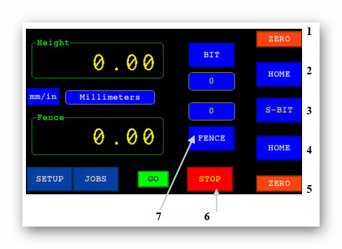
1 Bit Zero: Manually sets the current position of the BIT readout to Zero
2 Bit Home: Sets the top of the BIT level with the top of the table using the Touch plate. This is the starting reference position for the BIT and is the reference point against which the bit working position is calculated for Bit save and recall in the JOB files. The Height display will be auto zeroed if it has been selected in DRO Setup options.
3 S-BIT: Opens a select option window for auto Bit change position or, by using the touch plate, setting any part of the bit edge to be level with the router table top or other reference point.
4 Fence Home: Sets the Fence to the Home position and this is the reference start position used when saving the final working Fence position in a JOB file, the display will be set to Zero if Auto Zero option is selected in DRO Setup.
5 Fence Zero: Manually sets the current position of the fence readout to Zero.
6 STOP Aborts any current Auto movement, also see the Emergency STOP button.
7 Fence Keypad: Opens a Keypad for entering the required Fence position or offset position.
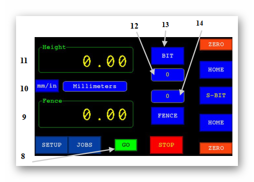
8 GO: Auto Fence and Height movements will not start until the GO button is pressed.
9 Fence Display: Shows the current position of the Fence relative to its Zeroed position.
10 mm/in: Toggles the Fence and Height displays between millimetres and inches.
11 Height Display: Shows the current Bit height (Router Lift) position display relative to Zeroed position
12 Height Auto move position: Displays the last value entered from the BIT Keypad display button (13) or the BIT height value from a JOB file if SET JOB had been pressed.
13 Height Keypad: Opens a Keypad for entering the required Bit position or Bit offset position.
14 Fence Auto Move position: Displays the last entered value from the Fence Keypad display button (7) or the Fence position value from a JOB file if SET JOB had been pressed.(1) Our small workshop layout __ (2) Bandsaw circle cutting jig __ (3) Spindle sander modifications __ (4) Dust Sensor
(5) Router table redesigned ____ (6) DC and where it all began __ (7) Bandsaw dust extraction build
-
14th March 2019, 08:58 PM #25
Supporting my wife's hobby.
- Join Date
- Nov 2013
- Location
- Caboolture QLD AU
- Posts
- 781
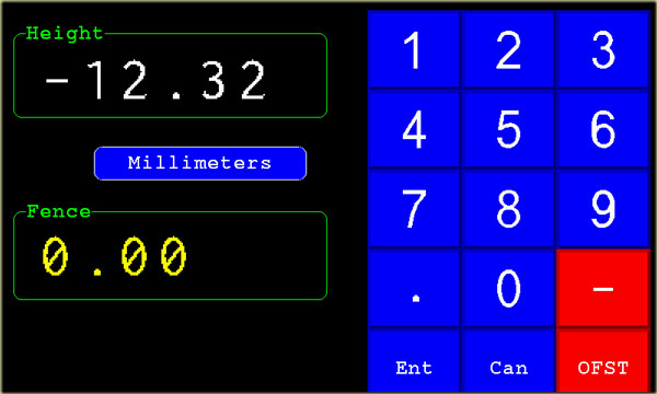
When the BIT button (13) or Fence button (7) are pressed, the manual entry keypad above is displayed.
In this case the FENCE keypad is displayed and the current Fence position is displayed as normal in the Fence display box. The new Fence value entered will be displayed in the empty Height display box, in this case [ -12.32 ] has been entered as an offset.
The value entered will be a positive value unless the negative sign is pressed, this can be pressed at any time, the minus sign is toggled with each press of the minus sign and the minus button turns red.
The value entered is an absolute position that the Height (lift) and/or Fence will move to unless the OFST button is highlighted. OFST tells the program to use the entered value as an OFFSET from current position. The button is toggled on and off with each press.
When OFST is selected the button turns RED.
When Ent is pressed the Keypad closes and depending on which keypad (Fence or BIT) was opened, the value entered will be shown in display box 12 or 14.(1) Our small workshop layout __ (2) Bandsaw circle cutting jig __ (3) Spindle sander modifications __ (4) Dust Sensor
(5) Router table redesigned ____ (6) DC and where it all began __ (7) Bandsaw dust extraction build
-
14th March 2019, 09:02 PM #26
Supporting my wife's hobby.
- Join Date
- Nov 2013
- Location
- Caboolture QLD AU
- Posts
- 781
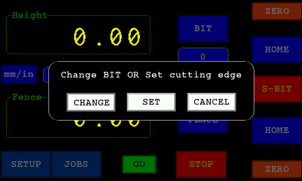
Pressing S-BIT will open the select option window shown above.
CHANGE: The Router Lift will move up towards the top of the table and stop at the position set by the Bit change Micro switch. This Micro switch is usually set to trip a few mm before the Router lift upper limit Micro switch. The bit change Micro switch is used to allow the Bit changing position to match the Router Motor and lift design.
SET: The Touch Plate must be plugged in and can be used as needed to set any part of the cutter edge level with the top of the router table or other reference. If the Touch plate is not plugged in, the Router Lift will move to the Bit change position, but this time it backs away slightly from that position as the Touch Plate timing function for SET was selected.(1) Our small workshop layout __ (2) Bandsaw circle cutting jig __ (3) Spindle sander modifications __ (4) Dust Sensor
(5) Router table redesigned ____ (6) DC and where it all began __ (7) Bandsaw dust extraction build
-
14th March 2019, 09:06 PM #27
Supporting my wife's hobby.
- Join Date
- Nov 2013
- Location
- Caboolture QLD AU
- Posts
- 781
Main Setup Screen Option buttons.
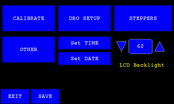
LCD Backlight sets the brightness level of the display, the lower the value the less power the display uses and less heat generated by the LCD backlighting
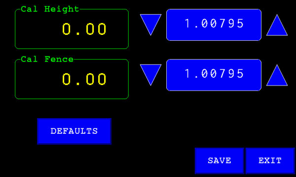
CALIBRATE Menu is used to set the accuracy of the Scale sender as it moves away from zero. Most of the iGaging DROs appear to use close to the same value, however this option allows you to calibrate each scale sender for best accuracy if needed.
 (1) Our small workshop layout __ (2) Bandsaw circle cutting jig __ (3) Spindle sander modifications __ (4) Dust Sensor
(5) Router table redesigned ____ (6) DC and where it all began __ (7) Bandsaw dust extraction build
-
14th March 2019, 09:08 PM #28
Supporting my wife's hobby.
- Join Date
- Nov 2013
- Location
- Caboolture QLD AU
- Posts
- 781
DRO Meun
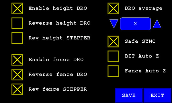
Here you can Enable or Disable a DRO and set the rotating direction of the Stepper to adjust for different mounting orientating and router table designs.
The DRO slide scales increment the position data value from low to high in one direction and decrement in the other, selecting Reverse DRO allows you to select the best mounting position for the DRO slide scale and still have the output correctly match the software controller as noted below.
The Software expects the Fence DRO numeric output value to decrease as it moves towards the back of the table. It expects the Height DRO numeric output value to decrease as it moves down away from the top of the table.
DRO average sums the number of readings shown in the adjustable up/down control box to give a more stable display with less hunting or flipping of the last digit.
Safe Sync should be left selected, it mainly effects the Manual rotary encoder updates.
BIT Auto Z will auto zero the height display when BIT HOME is finished.
Fence Auto Z will auto zero the Fence display when Fence HOME is finished.(1) Our small workshop layout __ (2) Bandsaw circle cutting jig __ (3) Spindle sander modifications __ (4) Dust Sensor
(5) Router table redesigned ____ (6) DC and where it all began __ (7) Bandsaw dust extraction build
-
14th March 2019, 09:12 PM #29
Supporting my wife's hobby.
- Join Date
- Nov 2013
- Location
- Caboolture QLD AU
- Posts
- 781
Stepper Motor Meun
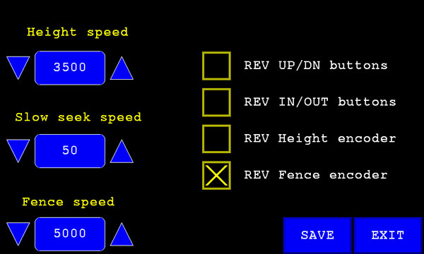
The maximum speed of the Height and Fence Stepper motors should be adjusted carefully. The maximum Fence speed is limited to around 5500, this is influenced by the size of the motors and the fact that the Fence drive has two motors in parallel. If the Fence speed is set to high, the stepper motors will start to vibrate and stall, this will cause them to get out of sync and the fence will start to skew.
The Router Lift speed should be kept to around 3500 as the travel is usually less than 100mm in normal use, keeping the speed down also reduces drive train shock and gives you time to press the Emergency Stop if you forget to move the Fence or Bit guard as the Router BIT is rising.
Slow Seek Speed: This is the lowest speed that the software will slow the stepper motors down to when automatically moving to a requested position. Setting a fast speed will cause the desired position to overshoot as the motor is slowed and the Software will have to backtrack even more at a micro speed to accurately set the position.
The Manual Router Lift UP / DOWN switch and the Fence IN / OUT switch can be set to work correctly even if mounted upside down or wired back to front. The same applies to the Encoders, you my also prefer to change the encoder direction for whatever feels natural to you with these check box options.(1) Our small workshop layout __ (2) Bandsaw circle cutting jig __ (3) Spindle sander modifications __ (4) Dust Sensor
(5) Router table redesigned ____ (6) DC and where it all began __ (7) Bandsaw dust extraction build
-
14th March 2019, 09:17 PM #30
Supporting my wife's hobby.
- Join Date
- Nov 2013
- Location
- Caboolture QLD AU
- Posts
- 781
Other Menu
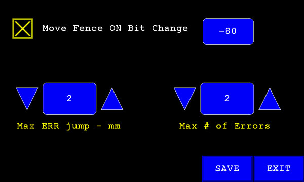
Having the Fence automatically move back to clear the bit when selecting the CHANGE BIT button is a handy safety feature, you can set the distance the Fence moves back from the bit before the bit is raised above the router table top to allow for any Fence Bit guard or other Fence design or attachment.
Max Error jump is adjusted when the Auto move option suddenly stops for no apparent reason, this can be caused by the Router motor or other workshop electrical interference, this option allows you to make the Auto Error Detect software less sensitive.
Max # of Errors The total error count allowed before the software stops the stepper motors, this can also be fine tuned in case the error is small but happens more often.
I am going to add a popup message widow to the controller software to make this cause of error obvious. BTW the only time I've had this error is when I had a faulty slide-scale USB cable.(1) Our small workshop layout __ (2) Bandsaw circle cutting jig __ (3) Spindle sander modifications __ (4) Dust Sensor
(5) Router table redesigned ____ (6) DC and where it all began __ (7) Bandsaw dust extraction build

 Reply With Quote

Similar Threads
-
Automated Guitars(s)?...or some such thing
By chrisb691 in forum MUSICAL INSTRUMENTSReplies: 5Last Post: 5th October 2012, 10:24 PM -
Automated milling and joinery
By BobL in forum SMALL TIMBER MILLINGReplies: 27Last Post: 17th May 2010, 11:39 PM -
Triton Router table RTA300 VS Carba-Tec Cast Iron Top Router Table
By pellcorp in forum TRITON / GMCReplies: 17Last Post: 30th April 2009, 02:43 PM
