

 Thanks:
  Likes:
  Needs Pictures:
  Picture(s) thanks:
Results 196 to 210 of 264
Thread: Yet another Router table build.
-
4th July 2018, 06:32 PM #196
 Woodworking mechanic


- Join Date
- Jan 2014
- Location
- Sydney Upper North Shore
- Posts
- 4,470

I see the situation now
 The fail safe system I mentioned, using a relay, can interrupt the step supply pulses from the arduino to the driver control,
I have used current sensors to control relays before so maybe that’s one method to use by se sensing router current.
On another note, I’ve almost finished my interface unit to go between the scale and the DRO display head as i’m still thinking of using the display head in my unit. Reason being, I’m looking at using a Nano so I have limited pins for a large display. Using a Mega would solve the problem but i’m looking at a cheap build
-
4th July 2018 06:32 PM # ADSGoogle Adsense Advertisement
- Join Date
- Always
- Location
- Advertising world
- Posts
- Many
-
4th July 2018, 07:56 PM #197
Supporting my wife's hobby.
- Join Date
- Nov 2013
- Location
- Caboolture QLD AU
- Posts
- 781
Yes that's a way to do it for the router motor - In my table the Router motor is controlled by a no voltage relay switch so I can use that for Router power indicator. On the subject of current sensing, that is one of the things I will do when I know the final load current of the Stepper motors, I should be able to detect a bind or something like not moving the fence before raising the router to change the bit. Some of the Stepper controllers I've used in the past had a terminal to monitor current.
FYI I've got the screw and Ball-nut drive mounted on a test board and have a DRO Slide next to it and coupled to the Ball-Nut. So those small Screw drives have 4 mm of travel per revolution, I can easily move in .01 mm steps just turning the shaft by hand, so the Stepper motor at 180 steps per revolution (180 steps = 4 mm) is just about perfect. Just getting a Stepper motor connected to it and I can start coding the closed loop control.
Also tried bulk force on both faces of the screw drive trying to detect a change in the DRO position - I could not - zero backlash for out use.
EDIT: Just realised I can measure DRO speed with the selected stepper motor speed (Screw drive speed) in the Code and if it's not within the parameters of travel I can halt the stepper.(1) Our small workshop layout __ (2) Bandsaw circle cutting jig __ (3) Spindle sander modifications __ (4) Dust Sensor
(5) Router table redesigned ____ (6) DC and where it all began __ (7) Bandsaw dust extraction build
-
4th July 2018, 08:35 PM #198
Supporting my wife's hobby.
- Join Date
- Nov 2013
- Location
- Caboolture QLD AU
- Posts
- 781
Just did a quick test, set the position of the ball-nut to 50 mm, told the Code to stop the scale if the lift position was Zero and Stop it at 130 mm at the other extreme, ran the motor at high speed in both directions and it stopped on a dime at both limits. Set auto reverses at the set limits and it ran back and forward between limits for as long as you like.
Thunderbirds are GO. (1) Our small workshop layout __ (2) Bandsaw circle cutting jig __ (3) Spindle sander modifications __ (4) Dust Sensor
(5) Router table redesigned ____ (6) DC and where it all began __ (7) Bandsaw dust extraction build
-
4th July 2018, 09:02 PM #199
GOLD MEMBER
- Join Date
- Jun 2005
- Location
- Helensburgh
- Posts
- 7,696
Well done, the electrons all went to the right place I guess.
 CHRIS
CHRIS
-
4th July 2018, 09:05 PM #200
Woodworking mechanic
- Join Date
- Jan 2014
- Location
- Sydney Upper North Shore
- Posts
- 4,470
Have you simulated what happens if the Micro loses the scale signal while the router is moving?
-
4th July 2018, 09:25 PM #201
Supporting my wife's hobby.
- Join Date
- Nov 2013
- Location
- Caboolture QLD AU
- Posts
- 781
Yes that's where the limit switches come in handy, seriously though, I'm looking for a change in position that's more than the current movement X steps. That problem only happens with interference from the Router motor, that has got to be addressed and I have some more ideas to try after using these in my current table. But it never looses accuracy unless there is an electrical (motor) glitch.
Well I'm heading off again for an early night.(1) Our small workshop layout __ (2) Bandsaw circle cutting jig __ (3) Spindle sander modifications __ (4) Dust Sensor
(5) Router table redesigned ____ (6) DC and where it all began __ (7) Bandsaw dust extraction build
-
5th July 2018, 01:29 PM #202
Supporting my wife's hobby.
- Join Date
- Nov 2013
- Location
- Caboolture QLD AU
- Posts
- 781
I have the Virtual keypad entry for offsets or absolute position entry running, I've coded fast acceleration to within 1 mm of the target position and auto switching to micro stepping for the last mm, the stepper and DRO scale move to within +/- 0.005 mm of the target value, and this is just a jury rigged lash up
(1) Our small workshop layout __ (2) Bandsaw circle cutting jig __ (3) Spindle sander modifications __ (4) Dust Sensor
(5) Router table redesigned ____ (6) DC and where it all began __ (7) Bandsaw dust extraction build
-
5th July 2018, 09:19 PM #203
Supporting my wife's hobby.
- Join Date
- Nov 2013
- Location
- Caboolture QLD AU
- Posts
- 781
Another kind forum member has generously helped me with a Nema 23 SKU: 23HS45-4204S, this is the unit I will be using, now this is more than required to move a fence and should have no trouble with the Router.
SPECS:
Holding Torque: 3.0Nm(425oz.in)
Rated Current/phase: 4.2A
Voltage: 3.78V
For anyone wondering why I went for this larger motor in the Nema 23 range, well a number of parameters affected my selection.
1: Holding Torque.
2: Heat.
3: Grunt for speed under load.
4: It only cost a few dollars more.
This unit can hold the weight of a Router with only 1/2 the holding current. I exerted over 70 LBS on the Screw Drive Bearing NUT and I could'n budge it at half current.
Three hours of holding current and it's barely warm to touch. This obviously is not in a CNC and therefore will get very little working time, so running heat was never going to be a problem.
I ran a number of tests with the Stepper Drive Controller at 28 volts instead of 40 and set it below it's rated operating current for another holding test, still could not move the drive with over 70 LBS applied. Can't remember the last time I pushed against a router fence that hard.(1) Our small workshop layout __ (2) Bandsaw circle cutting jig __ (3) Spindle sander modifications __ (4) Dust Sensor
(5) Router table redesigned ____ (6) DC and where it all began __ (7) Bandsaw dust extraction build
-
6th July 2018, 11:17 AM #204
Supporting my wife's hobby.
- Join Date
- Nov 2013
- Location
- Caboolture QLD AU
- Posts
- 781
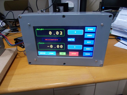
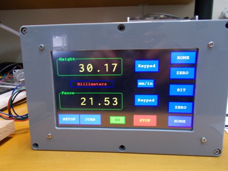
The rough test set-up for coding the auto position control loop.
The long buttons with 0 in them open a Virtual Key Pad, one for the Fence and one for the Router Lift.
Green button = GO, the Red button is the emergency STOP, obviously there will be a real button for that as well.
There will be a small control panel with two Rotary encoders, one for the Fence and one for Router Lift fine adjustments, two sets of 2 buttons for fast Fence IN/OUT and Router Lift UP/DOWN, and an emergency STOP button. So you have the option of not using the Touch screen buttons for simple things.
BTW: I applied that same 70 LBS to the Drive Ball-Nut with NO power (no motor Holding voltage) I still could not move the drive.
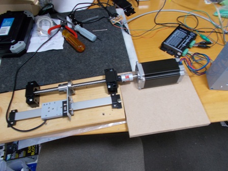
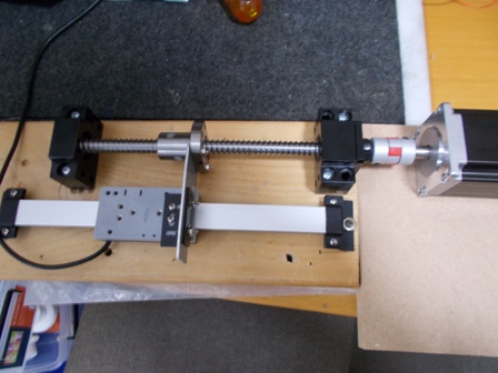
Photo 2 shows the DRO Scale slide, the Nema Stepper motor connected to the screw and Ball-Nut drive. The Scale slide is attached to the Ball-Nut with a bit of aluminium, and behind the rear of the motor is the Stepper motor Drive controller. (small black box).
 -
-  -
-  (1) Our small workshop layout __ (2) Bandsaw circle cutting jig __ (3) Spindle sander modifications __ (4) Dust Sensor
(5) Router table redesigned ____ (6) DC and where it all began __ (7) Bandsaw dust extraction build
-
6th July 2018, 06:57 PM #205
Woodworking mechanic
- Join Date
- Jan 2014
- Location
- Sydney Upper North Shore
- Posts
- 4,470
B?!#ger. Timbecon has igaging gear on special next week!!!
-
6th July 2018, 07:08 PM #206
GOLD MEMBER
- Join Date
- Oct 2013
- Location
- Perth, Australia
- Posts
- 1,813
Was just thinking the same thing, just bought a stack of iGaging products last month [emoji19]
-
6th July 2018, 07:19 PM #207
Member
- Join Date
- Mar 2018
- Location
- Melbourne, Australia
- Age
- 70
- Posts
- 80
Was at Timbecon today, spent a whole $20.00. I love my Absolute Origin Vernier Caliper but I don't think Timbecon sell that model.
"iGaging Precision Savings
All items below are on special through to 31st..."
https://www.timbecon.com.au/site-sea...ng&pageindex=1
-
10th July 2018, 09:45 PM #208
Supporting my wife's hobby.
- Join Date
- Nov 2013
- Location
- Caboolture QLD AU
- Posts
- 781
I'd have liked to have some table mod updates to show, but alas I've been stuck with writing the Control Software. The hardware is, in reality, rather simple for the most part, and these components have already been proven in other applications. As I spent time testing the DRO scale and stepper drive, I soon realised that the Control program was either going to make or totally break the use of this system for any sort of closed loop automated control. There are numerous ways that you can induce interference into the DRO scale data, I spent a lot of time eliminating those. Another important problem that needed to be addressed was Scale error control from every possible source or reason. As each installation is different, there had to be a simple way to adjust error limits, and more importantly, alert the operator and halt the operation in a sophisticated fashion. This has at last been achieved while keeping the control screen as simple and as uncluttered as possible, no stupid pop up messages to read and click, again all achieved.
Finally, I have auto ramp up speeds to full movement speed then ramp down speeds to the final last mm, this has made the accuracy very impressive, dial in 12.01 mm and it moves that exact amount or position, if you want to move 0.01 mm then simple dial in 0.01 (or -0.01) and press the OFS button (OFFSET) on the keypad, the Fence or Router will move exactly 0.01 mm offset from the current position.
One of the nice feature of the "JOB screen" is this, you have the table set up for a routing task, you want to test different cutting results with slightly varying Bit depth and/or Fence positions but don't want to manually readjust the starting positions of the fence and bit every time, simply press the job button, in the JOB screen press the New Fence and New Height buttons (this Auto fills in the current fence and height positions), press Save and your done. Any time you need to quickly reset back to the start position, simple press the SET JOB button and press GO.
Since making the improvements I have not (as yet) been able to induce an error from either operator or external interference. Tomorrow I can finally start on the hardware conversion of the R-Table.(1) Our small workshop layout __ (2) Bandsaw circle cutting jig __ (3) Spindle sander modifications __ (4) Dust Sensor
(5) Router table redesigned ____ (6) DC and where it all began __ (7) Bandsaw dust extraction build
-
12th July 2018, 04:22 PM #209
Supporting my wife's hobby.
- Join Date
- Nov 2013
- Location
- Caboolture QLD AU
- Posts
- 781
The second stepper motor just arrived and I had the chance to test my controller running two drive units simultaneously. The Fence and router lift drive unit positions were set by selecting a test JOB (Contains both Fence and Router lift position values) and then pressing green GO button, both the Fence and Router Lift then ran together, as the Fence locked to its requested position it turned the GO button from Red to Gray indicating that only one position had been reached (the Fence), when the Router Lift finished a few second later and locked, the GO button then turned green. This is the first time I've had a chance to actually test the controller with two motors being speed controlled and their DRO's monitored together in the dual closed-loop control code.
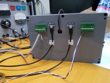
I found a simple way to mount the two USB connectors for the two DRO Scale slides, For the Stepper control cables I fitted the same style of sockets as those fitted to the Stepper Drive boxes. IE: 6 Pole PC Mount Pluggable Headers that accept Pluggable Terminal blocks.
I used this style of mounting to allow me to easily fasten the cables to the back below each connector, it makes it simple to plug and unplug, the plug in terminal blocks for the Stepper control wiring use screw down connections, same as the Drive controller, this makes it easy to install with no soldering required, and these are really high quality fittings. The lead coming out of the hole is a temporary programming cable to the PC, that will be covered with another Green terminal block for manual fast UP /DN buttons for the Lift and Fence. The cable connectors will be covered with a thin perspex cover mounted on 4 standoff spacers. BTW it's only test prototype.
 -
-  (1) Our small workshop layout __ (2) Bandsaw circle cutting jig __ (3) Spindle sander modifications __ (4) Dust Sensor
(5) Router table redesigned ____ (6) DC and where it all began __ (7) Bandsaw dust extraction build
-
12th July 2018, 04:46 PM #210
SENIOR MEMBER
- Join Date
- Dec 2017
- Location
- Aldinga Beach
- Posts
- 478
Good going


 Reply With Quote


Similar Threads
-
Router table - Build or buy?
By Dazm in forum ROUTING FORUMReplies: 9Last Post: 12th November 2015, 11:35 AM -
New router table build - no really!
By snowyskiesau in forum ROUTING FORUMReplies: 24Last Post: 14th November 2013, 08:02 AM -
New router table build
By snowyskiesau in forum ROUTING FORUMReplies: 12Last Post: 27th May 2012, 01:35 PM -
Another router table build.
By Nihilist37 in forum ROUTING FORUMReplies: 2Last Post: 31st May 2009, 07:30 PM -
Want to build a table for router and cms
By Guy in forum HAND TOOLS - POWEREDReplies: 3Last Post: 23rd June 2004, 12:31 AM
