

 Thanks:
  Likes:
  Needs Pictures:
  Picture(s) thanks:
Results 226 to 240 of 264
Thread: Yet another Router table build.
-
15th July 2018, 08:18 PM #226
 Supporting my wife's hobby.


- Join Date
- Nov 2013
- Location
- Caboolture QLD AU
- Posts
- 781

And one for Chris, you will be glad to hear that I've decided on the simplest mounting for the Fence slide, should only take a couple of hours to convert it and get some testing, I'll post a few photos of the rough test and maybe a short video of it running. This should reveal the amount of play and variation in the slide rails and position feedback with respect to the Fence under load. This mounting method means that I only need a single flat plate to tie the Fence, Screw drive and DRO together. No mods to the existing Fence or Table.
(1) Our small workshop layout __ (2) Bandsaw circle cutting jig __ (3) Spindle sander modifications __ (4) Dust Sensor
(5) Router table redesigned ____ (6) DC and where it all began __ (7) Bandsaw dust extraction build
-
15th July 2018 08:18 PM # ADSGoogle Adsense Advertisement
- Join Date
- Always
- Location
- Advertising world
- Posts
- Many
-
16th July 2018, 03:38 PM #227
Supporting my wife's hobby.
- Join Date
- Nov 2013
- Location
- Caboolture QLD AU
- Posts
- 781
Fitting the Fence drive has been scaled back as the pain from PS-Arthritis has decided to go even more ballistic today, even walking is now a chore.
I still managed to get the existing router out of the table, the table top is quickly removable so that makes it easy for the conversion. However before I removed the router I decided to retest the Control unit. Yesterday evening I had fitted the last of the connectors to the back of the Touch screen Control unit so all the wiring was complete and terminated correctly.
So I retested it again with the existing DRO scale still mounted only 50 mm from side of the Triton Router. There now was just NO way to induce an error in the reading when using the Control micro displaying the position on it's 7" touch screen. Nothing I could do with router speed settings made any change, slowly pressing the NVR switch in so that it basically arced the 240v contacts did nothing. FYI I had the display unit sitting on the table, almost above the router, seriously impressed but I still feel like crap.
Anyway, I've realised that I can easily make the fence removable from the drive unit. This was important as I was going to mount the drive system to the underside of the table top in order to hinge the table top and drive unit as a complete unit, or at least make the top removable as it is now.
FYI The Drive unit consists of: Two bearing Rails, One screw drive, DRO scale and stepper motor).
So making the Fence "easily" removable allows the Drive system to mount to the side of the Router table cabinet and not the Table top, if you look at previous posted pictures you will see that the Table top overhangs the cabinet sides by (as chance would have it) about the same amount as the height of the Drive components that support the fence, almost nothing will protrude past the side of the table top with the exception of the Stepper motor and fence connecting plate, but only slightly. It will take the same amount of time to remove the fence as it does now, by undoing two large knobs, there will be guide pins as well to positively locate the fence to the side plates, it will definitely lock down 100% solid.
In reality the only reason I would remove the top is to modify something. I know that some of us want to hinge the top to change the bit on a Spindle motor, although with 140 mm of spindle / router motor travel available there should be no real reason to do that? and again I can move either motor 140 mm in 12 seconds, so from the normal working heights you'd be looking at around 4 seconds to change bit height.
One other point is that with a spindle motor you don't need the Table top compromised with a big insert plate. Again, look at earlier pictures of this build, there is a 160 mm x 40 mm hole in the table top for dust extraction around the bit, you only need to recess around that opening and make drop in insert-rings with a cut-out needed for the type of routing you are doing, again I showed this earlier on and it's what I've been using, but I can make then much smaller now as a spindle motor (and my modified Router) will no longer need to attach to the table top, they are mounted on a another small set of bearing guide rails and a screw drive which form the basis of this new router lift that is independent of the Table top. This new lift can be used manually by a removable through-table handle or, in this case, a Stepper drive.
I'm off to apply some more heat packs.(1) Our small workshop layout __ (2) Bandsaw circle cutting jig __ (3) Spindle sander modifications __ (4) Dust Sensor
(5) Router table redesigned ____ (6) DC and where it all began __ (7) Bandsaw dust extraction build
-
18th July 2018, 02:30 PM #228
Supporting my wife's hobby.
- Join Date
- Nov 2013
- Location
- Caboolture QLD AU
- Posts
- 781
Chris you were right, I got out the angle grinder and a brand new cutting disk and made very short work of SS bearing guide rail. One bearing rail and screw drive attached, just fitting the motor and scale now, the other half of the bearing rail (the one I cut) then goes on the other side. Just have to make two connecting plates for the fence to the guide bearings and I can start measuring the mechanical play at the fence and testing with the controller. I'd say tomorrow mid morning as I have to go grab a bit of thick aluminium plate first. I'll post an in progress pix of the Drive side of the fence today if I get it sorted. Amazing how much easier things are when you're not being pile driven into the ground with pain, it's a lovely warm day, shorts and t shirt and that helps.
BTW the 400 mm screw and ball nut drives I bought are a perfect match for the 300 mm DRO and the 370 mm (750 mm rail cut in half) bearing guide rail.(1) Our small workshop layout __ (2) Bandsaw circle cutting jig __ (3) Spindle sander modifications __ (4) Dust Sensor
(5) Router table redesigned ____ (6) DC and where it all began __ (7) Bandsaw dust extraction build
-
18th July 2018, 08:00 PM #229
Supporting my wife's hobby.
- Join Date
- Nov 2013
- Location
- Caboolture QLD AU
- Posts
- 781
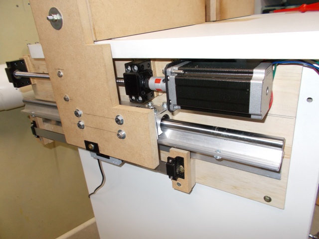
The trial fit up, what you can't really see is the overhang of the fence, the rail is positioned to allow the fence to go back past the edge of the table, should allow me to almost never have to take it off. The vacant hole above the front draw next to the motor, has a battery supply for the current DRO setup, it will also house the power supply and stepper drivers, they run cold but there will be ventilation, the plan is to match the other draws but make it a slide out tray, similar to the router bit draws, that should give me enough access at any time, means there will be virtually no wiring showing except for the loop in the DRO Scale cable. Of course the Table top comes off easily when needed for full access..
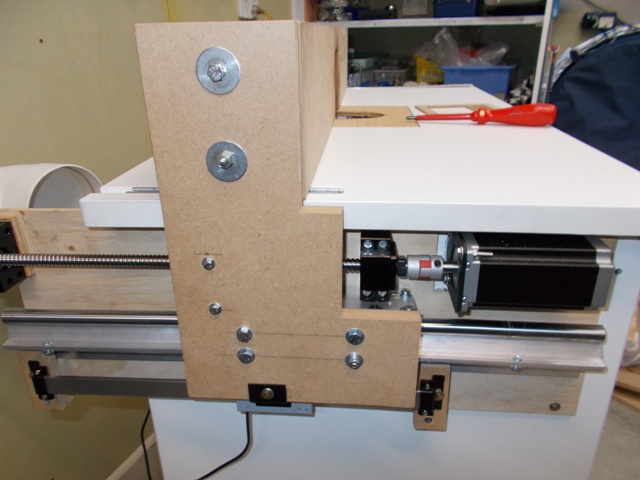
The second picture shows the spacing I'll be using for the guide rail bearings, a plate will tie the side of the fence sown to the slide bearings, the bearing nut on the screw drive and on to the Scale slide. Limit switches have to be added and then it's ready for some testing.
 -
- 
 (1) Our small workshop layout __ (2) Bandsaw circle cutting jig __ (3) Spindle sander modifications __ (4) Dust Sensor
(5) Router table redesigned ____ (6) DC and where it all began __ (7) Bandsaw dust extraction build
-
18th July 2018, 08:05 PM #230
SENIOR MEMBER
- Join Date
- Dec 2017
- Location
- Aldinga Beach
- Posts
- 478
You are making really good progress....well done!!
-
18th July 2018, 08:51 PM #231
Woodworking mechanic
- Join Date
- Jan 2014
- Location
- Sydney Upper North Shore
- Posts
- 4,470
Looking good.

I notice you are using a flexible coupling from the shaft to the stepper. I’ve got a different design and it’s causing accuracy problems as it can extend and retract slightly. Yours looks as though it won’t do that?Probably less of a problem with the router lift because it’s vertical but definately caused problems in the horizontal. I have a solid coupling on order and it should be here a Friday.
-
18th July 2018, 09:06 PM #232
Supporting my wife's hobby.
- Join Date
- Nov 2013
- Location
- Caboolture QLD AU
- Posts
- 781
Thanks, there's no twisting if that's what you mean, it's like a tight interlocking part, the shape allows it to flex for any slight non-alignment. I have to say that they are beautifully built.
It can be pulled apart, but it could never be moved apart once mounted as it's wedged between the motor and drive bearing block, the screw drive load bearing block wont allow any in out movement in the coupling or motor to have any effect.(1) Our small workshop layout __ (2) Bandsaw circle cutting jig __ (3) Spindle sander modifications __ (4) Dust Sensor
(5) Router table redesigned ____ (6) DC and where it all began __ (7) Bandsaw dust extraction build
-
18th July 2018, 09:16 PM #233
GOLD MEMBER
- Join Date
- Jun 2005
- Location
- Helensburgh
- Posts
- 7,696
I priced some new 10mm aluminium plate today and my credit card had a heart attack and self destructed to prevent further use.
To clarify what follows the intention is to have two vertical rails mount to the side wall of the cabinet and the spindle will mount to the rails via a plate or a small panel. Doing that removes the load from the top caused by a lift and router and also allows the top to be quickly removed, now read on.
The spindle really only needs a flat bar between the two vertical rails, there is so little friction that the chance of it skewing is negligible. I was thinking originally of a plate so it sat on four bearings (two on each rail, one upper one lower) to minimise movement or skewing if it was only attached to two bearings. If there was any doubt four bearings could be used, join the upper and lower bearings with two plates or joiners then attach the horizontal rail which the spindle bolts to and bolt each end of that to the vertical rails but I think doing that is overkill. Basically it would be a H with the spindle on the horizontal of the H and bearings at the top and bottom of the two verticals.
Having said that if you wanted to use more than one spindle a horizontal rail would allow multiple mountings that would be along the same axis and equidistant from the fence so all digital measurement would be the same from each spindle. This would be really advantageous in a production workshop more than a hobby one. I think a second spindle could be added for under $200 easily.
Thinking about bolting the spindle bracket to the horizontal bar, I will first bolt it then drill through the bracket and bar and insert some roll pins so if it is removed it goes back into exactly the same position. That eliminates the need to allow for the clearance that any bolt hole has.CHRIS
-
19th July 2018, 08:36 PM #234
Supporting my wife's hobby.
- Join Date
- Nov 2013
- Location
- Caboolture QLD AU
- Posts
- 781
Started out looking for some meal plate, most locals to busy to help at the moment, realised that I should be using some MDF anyway to make the brackets and get an idea of what will and wont work and use them as templates.
First off some bad news, I was naive to think that a 900 mm long Fence would not have tremendous leverage over it's length to the opposite end. It's to much to ask of the bearing rails to hold the force that could be exerted, although they are impressive and didn't move with the small force I applied, I tried end plates of 6 mm MDF and the flex results in a large amount of movement for a little flex over the length of the fence, now even if you used solid steel plates you would likely damage the bearing rails and it would still have enough flex to be a problem.
So the best solution is to add a second screw Drive and stepper to the other end, the steppers are running at 1/2 current so the controller should have no problem but I'll do some testing tomorrow.
The Good news: There is no vertical deflection of the fence, it feel rock sold and here the bearing rails really shine, and the Fence travels effortlessly across the table, so with the extra components it will be great. I am fortunate to have at the moment a second screw drive and stepper so I'll try and test it out tomorrow.
I got side tracked this morning as well with the DRO mounting. These DRO Slides travel from a low value reading to high value reading in one direction, you can't reverse it unless you turn the DRO around or upside down, and often the mounting position then has the cable on the wrong side or it has scale slide connection holes upside down. This was the problem I faced when first using them and you can't modify the slide, so your stuck with it.
I came up with some code to swap the read direction in software and then added Tick-Box options for each Scale to allow you to reverse the HO to LO value output direction with one touch.
EDIT:
One thing I wanted to add to the fence end plates and fence movement from end to end problem, even though BOTH ends are on bearing rails, and they aren't introducing any flex themselves, the driven end of the fence is locked solid by the Screw Drive, but the non-driven end is free to move slightly back and forth on the bearing rails. So it needs a screw drive as well to lock it down.(1) Our small workshop layout __ (2) Bandsaw circle cutting jig __ (3) Spindle sander modifications __ (4) Dust Sensor
(5) Router table redesigned ____ (6) DC and where it all began __ (7) Bandsaw dust extraction build
-
20th July 2018, 09:31 PM #235
Supporting my wife's hobby.
- Join Date
- Nov 2013
- Location
- Caboolture QLD AU
- Posts
- 781
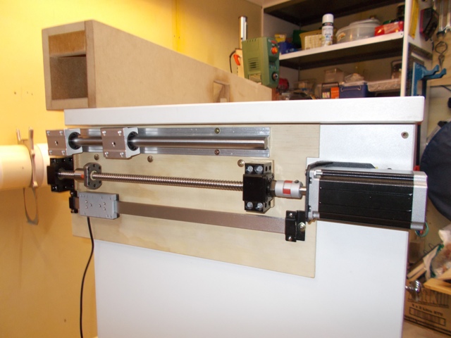
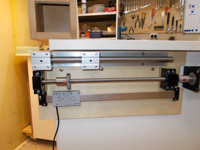
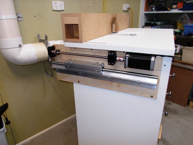
Started from scratch with version two of the Fence Drive unit. Moved the screw drive and stepper to the top, moved the motor back from the edge and made the Fence move completely off the back of the router table, now I don't have to remove the fence in order to remove the Top. This makes access to the mechanicals, router lift, concealed cabling, stepper motor controllers, power supply and associated circuits a breeze. There is nothing attached to the Router table top in this build, not even the router Lift or router / spindle motor. I have a new Top waiting for when I finish everything, I bought a spare top for $10 way back when I first built the table.
DRO scale will sit just below the Bearing rails, the bearing rail has been turned to the correct load bearing orientation and the two bearings supports have been separated even further for load spreading and stability, they are tied together with an aluminium angle bracket, the bracket in turn will attach to the Fence end plate.
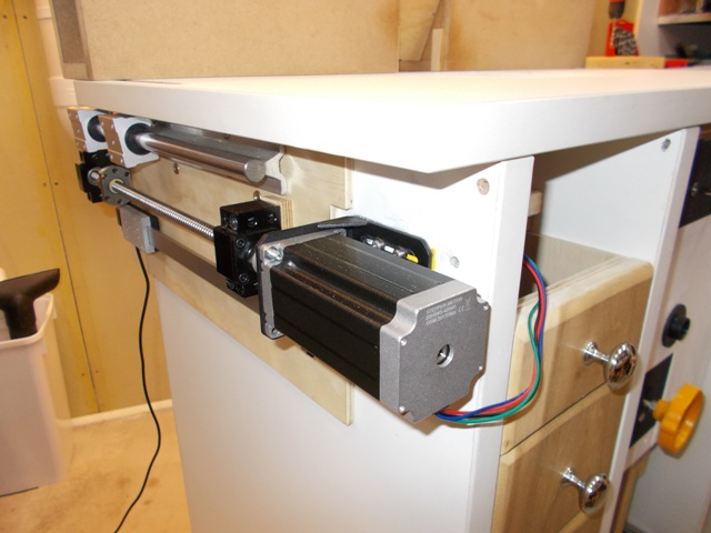
BTW Everything except 12 mm of the motor is inside the Table top overhang on each side. In other words, there is almost nothing sticking out at the side.
 (1) Our small workshop layout __ (2) Bandsaw circle cutting jig __ (3) Spindle sander modifications __ (4) Dust Sensor
(5) Router table redesigned ____ (6) DC and where it all began __ (7) Bandsaw dust extraction build
-
21st July 2018, 08:36 PM #236
Supporting my wife's hobby.
- Join Date
- Nov 2013
- Location
- Caboolture QLD AU
- Posts
- 781
Had the first run of the fence using the Controller.
A few things first:
This configuration is much better than the first attempt and resists more of the yaw from the non driven end of the fence, but there is still a lot of springiness created by the 17 mm MDF Fence connection panels. And again, if there was not, you would likely break something, the Fence is almost ONE meter long, how much leverage do you think a 1 meter bar has? a lot!
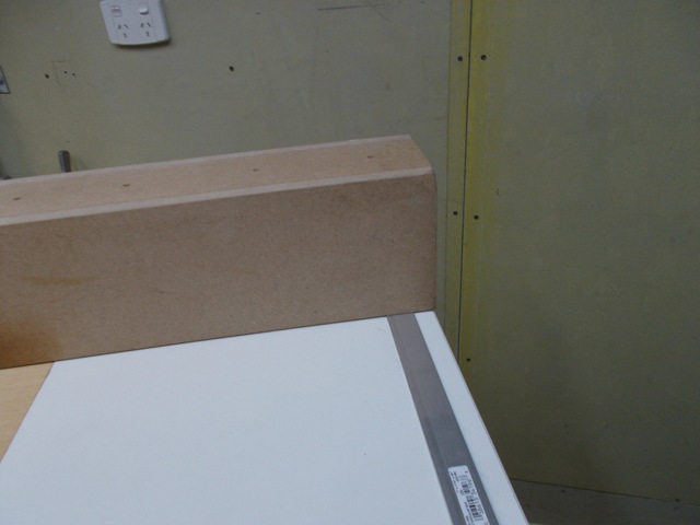
For this test I had only built one end, so the other end of the fence is dragging along the top of the table on an thin aluminium strip that keep the fence at the same height off the table as the driven end, the last picture shows this.
Keep in mind that the drive end is still a rough lash up to see if it works, I will be duplicating this on the other end as it went so well. I was able to return the fence to the exact position within 0.05 mm every time - measured at the drive end of the fence as the other end of the fence just dragging around, considering this, I was impressed.
By the end of tomorrow I should have both ends finished and both driven, I also noticed that it's easier and faster to move the fence with the electronics than it is manually as I don't have to unlock and relock the fence each time I move it.
This layout also makes adjusting and building the drive very easy when compared to the previous attempt. I'm very happy with the progress so far.
 -
- 
 (1) Our small workshop layout __ (2) Bandsaw circle cutting jig __ (3) Spindle sander modifications __ (4) Dust Sensor
(5) Router table redesigned ____ (6) DC and where it all began __ (7) Bandsaw dust extraction build
-
22nd July 2018, 08:39 PM #237
Supporting my wife's hobby.
- Join Date
- Nov 2013
- Location
- Caboolture QLD AU
- Posts
- 781
I pulled apart the side in the last post to use as a template for the opposite side, and being a sucker for punishment, I decided to use different backing timber and make a new drive for both sides, the sides are identical except that only one side has a Digital Scale position sensor.
I did a search for connecting two steppers in parallel and got a few hits from various CNC forums, most saying it won't work, or if it does the speed is compromised or the single drive controller has trouble with two drives and antiresonance algorithms in the DSP, ETC. Now I can certainly see this being a problem but it depends on the motors, current, load, difference in actual degree of step of each motor in micro stepping mode, the drive unit and slight variation in the screw drives themselves as to how well they track each other.
So I tested it anyway, these stepper motors are rated at 4.2 Amps and I'm currently only driving one motor at 1.91 Amps, I knew this would be a problem as one motor does not run properly at 850 ma, and that is what happens when that (current limited) 1.9 A is driving two motors instead of one, each gets 850 ma. When wired in parallel there was a limit as speed went up, one motor is driving a load and the other nothing, there are technical reasons as to why this is not ideal but I was looking to make this cause a problem, as soon as I upped the current to 3.7 Amps, both motors ran and tracked perfectly, so next test will be on the full system.
Another problem with driving both sides of a gantry (Fence in this case) is that one drive side can fail or loose step or any other reason that might cause one to stop / fail, you have exactly the same problem no matter how you dual drive, with the possible exception of using a long belt connecting the two drives and using one motor, but this is still a problem option in many ways, and a belt can break or the drive can jam.
The way around all of this is to use an encoder on both screw drives to constantly check for loss of drive or sync on either side, this makes it even more complex electronically and I did not want to do that, but there is a very simple way to do it for this installation.
In the case of a router table fence, we don't have the problem of a CNC as the router is not cutting when the fence is moving, so no danger of damaging the work piece, and there is more flex across the Fence in this design than a CNC, so it takes quite a bit of miss-stepping before there is a problem from a mechanical / breakage point of view, and this allows me to use a very simple method to monitor the rotation of each screw drive, as soon as one stops rotating, the micro cuts drive power until the problem is rectified, no damage is done and you also know that there will be a fence error in measurements from a slightly (I mean very, very slightly) skewed fence, simple!
BTW it only takes a few seconds to sync the two drives, they should stay like that unless there is a fault, but it will be later tomorrow before I've finished both sides and can really give it a torture test. I hope to have a short video if it all doesn't go pear shaped.
From the front of the table you can barely see the drive units on each side, unless you were looking for it you would likely not even notice them.(1) Our small workshop layout __ (2) Bandsaw circle cutting jig __ (3) Spindle sander modifications __ (4) Dust Sensor
(5) Router table redesigned ____ (6) DC and where it all began __ (7) Bandsaw dust extraction build
-
22nd July 2018, 09:04 PM #238
GOLD MEMBER
- Join Date
- Jun 2005
- Location
- Helensburgh
- Posts
- 7,696
Thanks for the progress report Mike, not much else I can say.
CHRIS
-
22nd July 2018, 09:17 PM #239
Supporting my wife's hobby.
- Join Date
- Nov 2013
- Location
- Caboolture QLD AU
- Posts
- 781
Thanks Chris, yes I'm just putting the reasoning behind my madness out there for those with a casual interest in the project.
BTW I've been racking my last remaining brain cell for a way to make an accurate "fence zero" electronic reference point, I think I've come up with a very simple, accurate, easily adjustable, completely automatic, robust and unobtrusive way to do do it. But I need to test it first before elaborating, it's so simple that it's almost ridiculous.
Tired, off to bed, cheers.(1) Our small workshop layout __ (2) Bandsaw circle cutting jig __ (3) Spindle sander modifications __ (4) Dust Sensor
(5) Router table redesigned ____ (6) DC and where it all began __ (7) Bandsaw dust extraction build
-
23rd July 2018, 09:50 PM #240
Supporting my wife's hobby.
- Join Date
- Nov 2013
- Location
- Caboolture QLD AU
- Posts
- 781
A very quick update, it's 8.37 pm, I'm tired and once again having an early night. I just this moment finished testing the completed fence by jury rigging the two steppers to the driver and my Micro Controller to give it a try before heading off. One word, beautiful, the Fence is as solid as if it were bolted down to the Table, and I mean you can't physically budge it.
Moves perfectly, tracks perfectly, If I push really hard against the centre of the fence I can get 0.01 mm to 0.03 mm of change in the Digital display, that is the same as when the Fence was bolted to the table in a normal fashion, it feels absolutely solid and the sort of thing you'd expect to pay a hell of lot for, it even sounds sweet. To be honest, this is better that I had hoped for.(1) Our small workshop layout __ (2) Bandsaw circle cutting jig __ (3) Spindle sander modifications __ (4) Dust Sensor
(5) Router table redesigned ____ (6) DC and where it all began __ (7) Bandsaw dust extraction build


 Reply With Quote
Similar Threads
-
Router table - Build or buy?
By Dazm in forum ROUTING FORUMReplies: 9Last Post: 12th November 2015, 11:35 AM -
New router table build - no really!
By snowyskiesau in forum ROUTING FORUMReplies: 24Last Post: 14th November 2013, 08:02 AM -
New router table build
By snowyskiesau in forum ROUTING FORUMReplies: 12Last Post: 27th May 2012, 01:35 PM -
Another router table build.
By Nihilist37 in forum ROUTING FORUMReplies: 2Last Post: 31st May 2009, 07:30 PM -
Want to build a table for router and cms
By Guy in forum HAND TOOLS - POWEREDReplies: 3Last Post: 23rd June 2004, 12:31 AM
