

 Thanks:
  Likes:
  Needs Pictures:
  Picture(s) thanks:
Results 31 to 45 of 101
-
23rd January 2016, 04:34 PM #31
 Supporting my wife's hobby.


- Join Date
- Nov 2013
- Location
- Caboolture QLD AU
- Posts
- 781

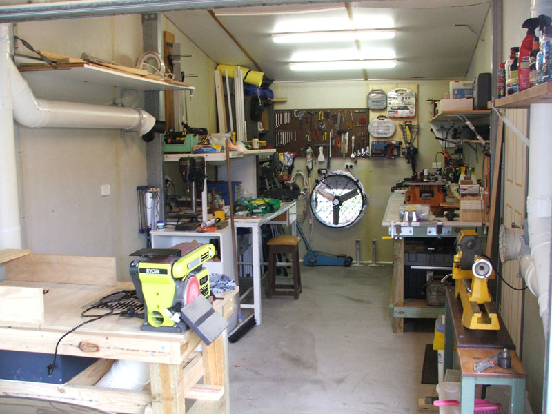
Bit of a fisheye effect but it gives an idea, not a lot of room in a 6 x 3 bay, it's lined with fibre cement, walls and ceiling are insulated.
-
23rd January 2016 04:34 PM # ADSGoogle Adsense Advertisement
- Join Date
- Always
- Location
- Advertising world
- Posts
- Many
-
25th January 2016, 03:38 PM #32
Supporting my wife's hobby.
- Join Date
- Nov 2013
- Location
- Caboolture QLD AU
- Posts
- 781
I'm going make an inclined manometer during the week and attempt to test the vacuum at the DC, then connect the system and test each port, hoping to see if I can get a better understanding of the flow rates and various system losses.
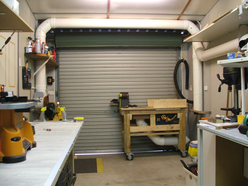
I may end up shifting the Y junction on the RH wall up to the center of the ceiling span, I'll then run the pipe (currently running below that very high white shelf) from the relocated Y connection across the ceiling and down through the shelf to the position of the band saw - once we establish the BS position.
Again, everything looks small in the picture, but to give an idea of size:
The bench on the left is over 3M long, 900mm deep and 1m high. bench on the right is almost 2m long. The space for the Band saw is over 2m from the drill press on the right to the moveable "dirty" work bench - dirty = dust from sanding, cutting, the bench saw, and various small hand tools.
Not only can the bench be moved outside for some tasks, but with the massive amount of air from the rear - through the wall - fan, when the door is raised (kind of like removing the wall), everything we do on that table disappears straight out the door. Of course we have the 150mm connection for the DC on the bench as well.
I'm also going to do what BobL suggested and put a squirrel cage extractor towards the high point of the ceiling near the lathe / band saw / table saw end of the workshop, it will exit through the wall or roof. That should enhance cross flow with the very low rear wall forced air intake, and importantly, the ceiling extractor can be left running most of the time to help remove any smoke like dust that rises from wood working and is missed by the DC hoods, along with any invisible stuff that can be stirred up when someone walks through the workshop or from their clothes.
-
25th January 2016, 03:40 PM #33
Supporting my wife's hobby.
- Join Date
- Nov 2013
- Location
- Caboolture QLD AU
- Posts
- 781
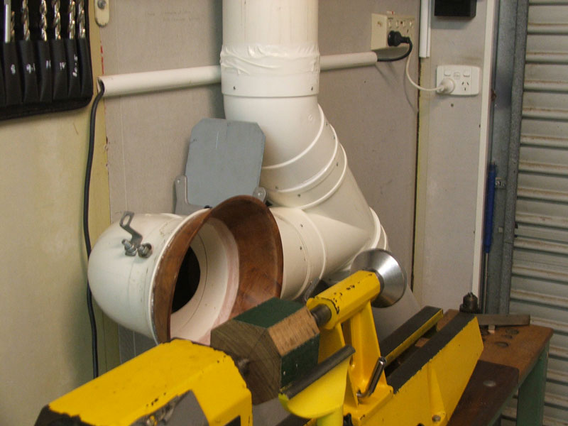
View of the DC pickup for the lathe, unfortunately, due to available space, I could not fit 2 x 45deg bends.
BTW. The small screws holding the duct fittings together do not go all the way through the inner wall. You can just feel the slightest raised spot where the tip of the screw stops just beneath the inner wall. The outer fitting is drilled so that the self tapper screw thread slips through and bites into the inner pipe wall as it is screwed in, this pulls the inner wall against the outer connector wall.
-
25th January 2016, 03:42 PM #34
Supporting my wife's hobby.
- Join Date
- Nov 2013
- Location
- Caboolture QLD AU
- Posts
- 781
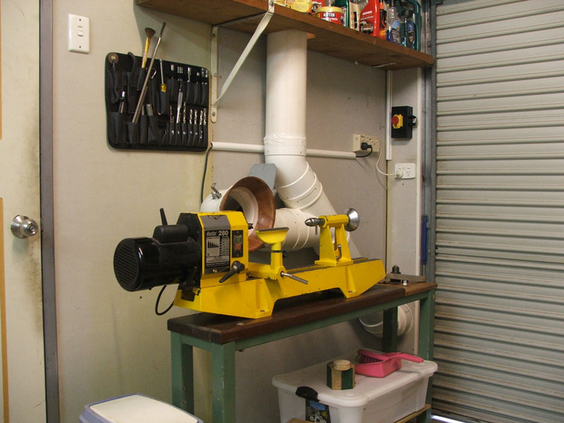
Another view of the run to the lathe, DC outlet is on the other side of the wall via a left turn 45 deg and then a 1m straight run into the Impeller.
-
26th January 2016, 06:04 PM #35
Supporting my wife's hobby.
- Join Date
- Nov 2013
- Location
- Caboolture QLD AU
- Posts
- 781
Made a manometer - tried to take some readings.
Initial test of DC in housing - 600mm of 150mm PVC running directly into the impeller:
10.75 inches.
With the 1.6m x 2.1m DC cabinet door open - no difference in reading.
NOTE: With the vacuum seal plate cracked open slightly - sucking air - reading goes to 12"?
Wondering if a bit of an air leak is causing slightly less cavitation at the impeller, so it pulls a bit more vacuum?
Current sealed: 4.3A.
Current with 600mm run to intake, pipe open = 8.7A @ 239 VAC, so around 2.7HP
Complete system connected: - Don't know if I'm doing this correctly - help appreciated.
I have the manometer connected to the 45 deg fitting sitting between the end of the 600mm pipe mentioned above and the system inside the Workshop. - Is that giving false readings there? where should it be?
Results with that connection:
Lathe: Has a temporary 142mm blast gate before a 90 deg bend to the bell mouth.
Vacuum: 7"
Current: 8.5A
So I assume you calculate CFM on the narrow blast gate - 142mm / 5.6" - and not 150mm ducting?
If so, best I can make out is 900CFM? Without the Gate it would be 1000CFM?
At the 142mm Flex connection blast gate for the bench saw:
This is at the end of 8m of 150mm stormwater and on the other side of the room.
Vacuum: 6.5"
Current: 8A
Again I took it as 5.6" ID pipe because of the Gate?
CFM = 850?
Band saw, don't have it yet and only have 2 x 4" temporary ports (needs 3), it's also on the other of the room and just after a 142mm blast gate - so:
Current: 8A
Vacuum: 6.5"
CFM: Don't know exactly what the true ducting diameter should be calculated at for 2 x 4" ducts? 4" = around 400CFM so 2 x 4 = 800CFM?
Hopefully those of you who have done this before can point out my errors / mistakes in a kindly informative fashion.
EDIT: All gates open: Vacuum 6" - I don't know how to calculate the CFM.
BTW I do realise that some of this is meaningless until I actually hook up the Bench saw and Band saw, but can't do that at the moment.
-
26th January 2016, 07:21 PM #36
.
- Join Date
- Feb 2006
- Location
- Perth
- Posts
- 27,785
The only pressure result that means something in terms of flow is the static pressure (10.7") this you can use on the "pressure"/"duct diameter"/"flow" chart to determine the maximum theoretical flow in a duct.
The 12" pressure measurement is probably just a turbulence artefact.
The other pressure results can''t be transferred into accurate flow because moving air generates a Bernoulli effect around a pressure sensing tip.
To measure flow with pressure you need to use a calibrated "pitot" tube which uses a fine double walled tube with holes in the ends and around the outer tube to measure the pressure differential between the tip opening and the average wall pressure around the outer tube. This eliminates the bernoulli effect and measure the true differential air pressure due to air speed.
What you can say with your measurements, provided the same size pipe is used and the pressure measured at the exact same point, a greater pressure loss means a higher flow.
Assuming you have done this then the bench saw has a pressure loss of (10.75 - 6.5) = 4.25" , while he lathe ducting has a pressure loss of 10.75 - 7 = 3.75"
This means the saw has a greater flow that the lathe. Given the ducting length and junctions involved I find that difficult to believe.
Can you confirm the pressure measurements are being made in the exact same location and depth into the duct.
Even slightly rotating the tip of the tube can alter a result.
What you can use the manometer on the same ducting line is to assess changes/improvements in hoods and junctions.
For example you could use it to test wether the salad bowl makes a difference compared to a naked duct - I don't think it will make much of a difference
Can you confirm the precise location of where the pressures are being made
-
26th January 2016, 08:21 PM #37
Supporting my wife's hobby.
- Join Date
- Nov 2013
- Location
- Caboolture QLD AU
- Posts
- 781
Thanks Bob, this is the information I'm after, I've looked up a few pitot tubes, so that will be the next thing.
The pickup point does not change in any way, it can't rotate or change depth in any way.
Now that I know more about the limitations of using it in this fashion, I'll take some time and make sure everything is as it should be and see if the readings are repeatable, glad I can use it for looking for changes in the same circuit, this will be of some help with moddifing the pickups when I get a chance.
-
28th January 2016, 04:23 PM #38
Supporting my wife's hobby.
- Join Date
- Nov 2013
- Location
- Caboolture QLD AU
- Posts
- 781
A few more basic tests.
I had disconnected the 700mm run from the DC at the shed wall to test static pressure, when I reconnected it to do tests for leaks inside the shed, I found I had introduced a small leak in the join to the shed, this was skewing things.
BTW. I removed the Y connection from the impeller to the dust bags, static pressure went up from 10 .7" to 10.9", motor current did not increase with 700mm of 150mm open ducting.
After fixing the leak, static pressure loss follows the layout and pickup size, the lathe with the most loss, followed by the bench saw port and lastly, that temporary 2 x 100mm adaptor for the band saw.
Calibrated pitot tubes are very costly - unless my Google searches results are faulty?
However after doing a lot of reading, I've decided that it's not worth my while wasting money trying to accurately measure something I can't easily change, that is, the limitations of the DC. When funds permit I'll definitely go for a big Cyclone, but for now I'm more interested in simply finding a way to set a base line and check for flow deterioration in the system over time, although in my case, this will almost entirely be due to filter seasoning - which I could care less about (DC is outside) except for the fact the it reduces air flow from the hoods - fortunately it's not had to clean the bags.
The second thing I would like to be able to do, is see the effect on flow with various modifications and trials with pickup hoods and hose connection to the tools. With this in mind, I'm looking for a way to indicate changes in air flow into the DC, something a bit better that simply measuring motor current.
I wondering, if I place a "simple" pitot tube, correctly pointing into the flow in the center of the ducting, connected to one side of a manometer, and a static tap on the side of the 150mm pipe, and connected to the other side of the manometer, will this give a better comparison of air flow "change" when compared to a straight static pressure reading on the manometer?
I'm not looking to calculate actual flow rate, I'm looking for a more sensitive change in flow rate indicator.
-
28th January 2016, 06:02 PM #39
.
- Join Date
- Feb 2006
- Location
- Perth
- Posts
- 27,785
Yes they are expensive. Most of what you are paying for is the cost of calibration as they all have to be individually done.. And then every measurement made has to be correctly converted from a pressure reading into an air speed. That's why a small profile hot wire anemometer that gives a direct air sped read out is the way to go. The propeller based anemometers are much cheaper BUT they are not designed to be used inside ducts as the prop severely interferes with the flow and gives readings that are much too high. Originally Posted by MandJ

But even hot wire anemometers are not that easy to use.
DC flow rates inside a pipe are RARELY STEADY and RARE UNIFORM so considerable patience is needed to make accurate measurements.
The air speed readings often jump around, sometimes a fair bit, requiring some sort of averaging to be made.
This is why a straight path test duct has to be used that is at least 5 duct diameters long. Inside a duct the air speed near the wall of the duct approaches zero while the max flow is closer to (but not always exactly in) the middle of the duct = a profile of air speeds needs to be measured and then mathematically integrated across the area. All this becomes a PITA to do when you are tweaking hoods etc. This si why you haven't seen me post much stuff on this in the last year or so.
Motor current appears to have some resolution to see changes, after all - 8.7 to 4.3A give you a difference of 4.4 in steps of 0.1A or 1 in 44 so the smallest change you can pick up is about 2.5% which is 25 CFM in a 1000 CFM system.The second thing I would like to be able to do, is see the effect on flow with various modifications and trials with pickup hoods and hose connection to the tools. With this in mind, I'm looking for a way to indicate changes in air flow into the DC, something a bit better that simply measuring motor current.
However in practice, even with my Fluke ammeter that can measure 10mA differences, I see the current jumps around ~ 20-30mA , and blocking the entrance to a duct doesn't bring about proportional changes in current.
I've had a half hearted try at doing this and did not have a lot of luck at the air velocities generated by DCs but please give it a go and you might be able to get it to work.I wondering, if I place a "simple" pitot tube, correctly pointing into the flow in the center of the ducting, connected to one side of a manometer, and a static tap on the side of the 150mm pipe, and connected to the other side of the manometer, will this give a better comparison of air flow "change" when compared to a straight static pressure reading on the manometer?I'm not looking to calculate actual flow rate, I'm looking for a more sensitive change in flow rate indicator.
I have made a pitot tube to sense the relatively slow speed air flow that supercharges my mains powered forge.
The air flow is provided by an old vacuum cleaner - if for whatever reason the air flow fails the forge flame will turn from a small intense blue-green flame to a large yellow fire ball!
The Pitot tube is connected to an air pressure switch so if the pressure drops below a certain level the switch immediately cuts the gas via a large solenoid.
-
28th January 2016, 08:26 PM #40
Supporting my wife's hobby.
- Join Date
- Nov 2013
- Location
- Caboolture QLD AU
- Posts
- 781
Thanks for answering Bob, gee you get to play with all kinds of neat stuff.
I spent around 4 hours reading technical files on various pitot tubes, the number or measurements needed, averaging and as you say, the general PITA involved to get accurate readings, so decided against it.
I found the same thing with current readings, unless there is a larger change in air flow it's seems a bit hit and miss when playing with small shape variations. I may give the simple pitot tube and static wall connection a go when I get time, if for nothing more than curiosity, but doesn't sound to hopeful.
BTW - Blast gates: I found a local plastic / Perspex / polycarbonate business. While I was getting a thick sheet of poly for the hood over the cross cut sled for the bench saw, I noticed some Perspex shapes that looked almost like one half of a blast gate, I described a blast gate to him and he said it would be simple to make one if I bring some 150mm pipe in for the fit up, quoted me $18 to build a gate to match the pipe inside diameter, and what I was looking at was very strong.
Mike.
-
28th January 2016, 08:44 PM #41
.
- Join Date
- Feb 2006
- Location
- Perth
- Posts
- 27,785
That's what being retired is all about for me. Originally Posted by MandJ

Part of my day job involved doing all this sort of stuff. I did heaps of open air air flow measurements with a propeller Anemometer and lots of large (12"+) duct measurements with a long Pitot tubes before we got the hot wire anemometers which made things easier but it is still difficult to measure small changes.I spent around 4 hours reading technical files on various pitot tubes, the number or measurements needed, averaging and as you say, the general PITA involved to get accurate readings, so decided against it.
I'm also interested to have a go at making a miniature pitot tube. I have a hot wire anemoneter that I can use to calibrate it, maybe I can calibrate yours as well?I found the same thing with current readings, unless there is a larger change in air flow it's seems a bit hit and miss when playing with small shape variations. I may give the simple pitot tube and static wall connection a go when I get time, if for nothing more than curiosity, but doesn't sound to hopeful..
It won't be as accurate as a bought one but it should still be reasonably close.
Sounds good - where's "local"?BTW - Blast gates: I found a local plastic / Perspex / polycarbonate business.
-
29th January 2016, 08:44 AM #42
Supporting my wife's hobby.
- Join Date
- Nov 2013
- Location
- Caboolture QLD AU
- Posts
- 781
Yes local shop, I'll take some photos when I get one made, if he keeps to that price and the quality is as good as the other pieces he had made, then it's just not worth my time making one. This is the basic web site for the local shop, but there appears to be similar business everywhere. Creative Perspex
I was just going to make a basic single port pitot tube, don't think I could make a dual port unit - is that what's called a static pitot tube? - although I could makes one out of copper tube but not sure if that would be ok, at least for me it would be easy to solder and shape, and I could likely use two over the counter tube sizes, now you have me thinking again- especially with the offer of even a basic calibration.
-
29th January 2016, 12:02 PM #43
 GOLD MEMBER
- Join Date
- Aug 2007
- Location
- Saskatoon, SK, Canada.
- Posts
- 1,439
HOT Wire USB LCD Digital Anemometer Wind Speed AIR Flow Temperature Meter GM8903 | eBay
NEW PRO HOT Wire Anemometer AIR Wind Flow Meter Thermometer | eBay
Bob would either of the above suit a woodworking club or an individual for testing the airspeed of their systems? I actually found another from China that was about $100US on my phone app earlier but can't find it now that I want to.
Pete
Found it.
Digital LCD HOT Wire Thermo Anemometer Wind Speed Meter AIR Flow Velocity Tester | eBayLast edited by QC Inspector; 29th January 2016 at 12:36 PM. Reason: added link
-
29th January 2016, 09:36 PM #44
.
- Join Date
- Feb 2006
- Location
- Perth
- Posts
- 27,785
It's good to see the prices of Hot wire Anemometers (HWA) finally coming down as the last time I looked the cheapest ones were still in the $300+ price range.
BTW the link to the last HWA does not ship to Oz but there are similarly priced ones that do.
I might buy one of these and testing it against my calibrated meter to see how reliable they are.
The problem with HWAs is that the cheaper ones only offer speed measurement up to 25m/s whereas what is needed for direct measurement of DC systems is up to 45 m/s.
Even though 1250 cfm through a 6" duct is 32 m/s , that will only a some sort of average speed across the duct.
The speed at the duct wall will be zero, but up to 25%+ above the average speed at other places (not necessarily even in the centre).
Measuring the flow in the pipe requires the internal cross section of the pipe to be divided up into symmetrical air cylinders and measuring the air speed systematically within these cylinders and performing a sum of the flows within the cylinders.
To purchase a 45 m/s HWA will require some serious money.
Even the two I have access to are only 30 m/s uncalibrated and a 20 m/s Calibrated.
To get around this I have used a Pitot tube from work to perform direct high speed measurements
The o there way to get around this this problem using HWA is to use a test piece of larger diameter pipe can be inserted into the flow to slow down the air speed so the slower speed HWA can read it.
The test piece meeds to be at least 5 duct diameters long and an access point for the HWS probe drilled half way along that length.
For 2" duct a 4" piece of ducting can be used, for 4" a 6", and for a 6" a 9" piece can be used.
For more details see here
Connecting power tools to DCs and VCs - some interesting measurements.
The larger diameter ducting testing method is a bit of PITA to used for testing machine ports etc in situ. as it requires a section of regular ducting be removed and replaced with the larger ducting.
It's often easier to perform testing using a separate duct to the ducting system.
-
30th January 2016, 05:24 AM #45
GOLD MEMBER
- Join Date
- Aug 2007
- Location
- Saskatoon, SK, Canada.
- Posts
- 1,439
Thanks Bob. I thought the 30m/s (first link) would be enough but perhaps by the fall when I'll need it the 60m/s puppies will have come down. Otherwise I'll just have to rely on accumulated wisdom and apply it wisely.
A buddy of mine has a number of pitot tubes from commercial passenger jets (heaters in them don't work) that he makes into weather vanes etc. If inserted into the duct at at fixed point when needed and hooked up to a water column, would it be enough to show the flow difference between clean filters and dirty ones?
Pete


 Reply With Quote
Similar Threads
-
For forum members only.
By nt900 in forum FESTOOL FORUMReplies: 2Last Post: 1st November 2011, 06:55 AM -
How many forum members ....
By Incoming! in forum WOODIES JOKESReplies: 16Last Post: 4th September 2008, 05:43 AM -
Forum has >20,000 Members
By dai sensei in forum ANNOUNCEMENTSReplies: 13Last Post: 3rd July 2008, 11:42 PM -
u.k. forum members
By jow104 in forum TRITON / GMCReplies: 1Last Post: 4th March 2004, 07:58 PM
