

 Thanks:
  Likes:
  Needs Pictures: 0
 Picture(s) thanks:
Results 16 to 30 of 108
Thread: Blast gate gallery
-
14th February 2017, 11:28 AM #16
 .
.


- Join Date
- Feb 2006
- Location
- Perth
- Posts
- 27,788
 Correct, I will draw up some cross sections to show some of the gates structures.
 Originally Posted by jmk89

-
14th February 2017 11:28 AM # ADSGoogle Adsense Advertisement
- Join Date
- Always
- Location
- Advertising world
- Posts
- Many
-
14th February 2017, 12:22 PM #17
.
- Join Date
- Feb 2006
- Location
- Perth
- Posts
- 27,788
An example of cross section of gates showing a couple of attachment methods i.e. screwing and gluing.
Screen Shot 2017-02-14 at 9.19.51 AM.png
-
3rd March 2017, 09:39 PM #18
.
- Join Date
- Feb 2006
- Location
- Perth
- Posts
- 27,788
Every now and then you need a BG in a awkward place like this.
IMG_2036.jpg
Not enough room for a rocker or full length standard slider so the only option is the usual plastic or metal gates that have an internally exposed sliding groove.
The groove tends to fill up with crap and requires cleaning - no biggie as it doesn't happen that often when using wood, but this ducting arm is going to be picking up a fair bit of metal swarf from the drill press so I really wanted one with a smooth bottom.
Here is what I came up with.
Here it is laying on its side. showing its smooth bottom
The flat piece of PVC is pushed down to a line but I will remake it so it is a bit longer and add a stop strip.
Open.jpg
The grey piece of PVC that is the gate comes out and flipping it over it allows it to close up against the smooth bottom
Closed.jpg
The slit in the PVC pipe was just two parallel cuts with a band saw.
I was really pleased how straight and parallel and tight filling the slot was and it just needed a bit of tidying up with a small file.
It's all currently held together with 2 and 3 mm bolts but I will eventually add some glue to strengthen and seal it up
side.jpg
And here it is in place.
Location2.jpg
-
27th March 2017, 10:36 AM #19
Senior Member
- Join Date
- Apr 2010
- Location
- Murray Lands SA
- Posts
- 221
Here's a Photo of a WIP, popular designed gates (Boss Loss)
 IMG_2458.JPG
-
27th March 2017, 11:39 AM #20
.
- Join Date
- Feb 2006
- Location
- Perth
- Posts
- 27,788
Looking good!
Thanks for the credit but it's not my idea. Originally Posted by mannum3
I got the idea from a link that Chris Parks posted a few years ago.
Initially I criticised the concept but now recognise that they are a good design when BG have to be located out of arms reach.
-
27th March 2017, 01:01 PM #21
.
- Join Date
- Feb 2006
- Location
- Perth
- Posts
- 27,788
I may have posted these elsewhere but thought I should also put them here for completeness of the gate gallery.
This is an all MDF rocker gate made by Bunbury Men's shed
The holes were cut with a router circle cutter
The sides and rocker are made from 9mm MDF while the flange is made from 12 mm MDF
BMSgate1.jpg
BMSgate2.jpg
While they were making flanges the Bunbury mens shed kindly made 8 more flanges for gates for my mens shed
I trust the PVC to MDF glue joint but not the MDF to Al line so I added CS screws
RockerMDFFlange.jpg
I seem to be making nothing but gates in the last few months.
RockerMDFFlange2.jpg
These 3 plus one in the pipeline make a total of 17 in the last few months. Hopefully this is the last of them for a while.
-
27th March 2017, 07:33 PM #22
 GOLD MEMBER
- Join Date
- May 2011
- Location
- Albury
- Posts
- 3,034
Please don't call Bob 'Boss', you'll only give him a big head! Originally Posted by mannum3

You've certainly been pumping them out Bob and that design makes a very good use of material if you have the right size.
Just spent 5 minutes looking for an emoji for 'thinking', couldn't find one though.
-
22nd April 2017, 08:03 PM #23
Supporting my wife's hobby.
- Join Date
- Nov 2013
- Location
- Caboolture QLD AU
- Posts
- 781
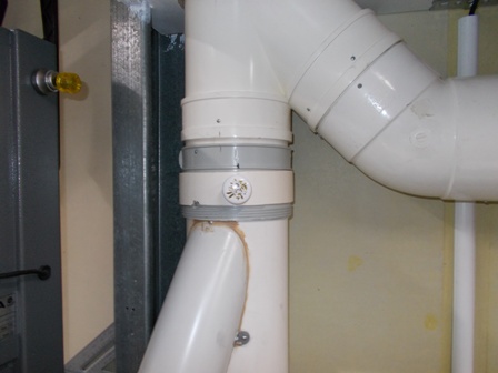
Simple blast gate for a small space
I posted a separate thread for this but added here for anyone facing a similar situation.
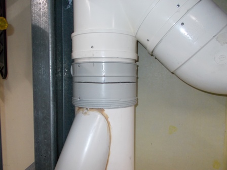
I was in the process of rearranging the workshop and of course things never go quite to plan, the vertical part of the ducting was just a bit to close to a big steel upright and no room for a conventional blast gate to operate. I needed to get something fitted and running quickly.
I had on hand a thick beefy threaded coupling (not sure of the correct name) but normally a cover is screwed over the threaded end. I remembered a blast gate design that BobL had posted (in this thread Post #18) and with the bits I had I came up with this BG in a hurry.
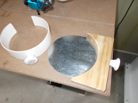
I cut a fine slot half way through the side of the coupler (I did the coupler separately in case I stuffed up), I then fitted the 150mm pipe into the coupler and fixed it in place, then remade the cut through the 150mm pipe. The two together were strong enough that no other bracing was needed. I cut and slider out of 0.97mm steel, very thin and importantly, extremely rigid. This plate is available from the Green shed, enough to do at least 4 x 150mm blast gate slides for around $18.00, however I had some scrap on hand for this.
I didn't get fancy, I just cut a small sleeve out a scrap of 150mm pipe to pop over the blast gate slot when the slide is out (gate open). In reality, the amount of vacuum lost through that 0.97mm slot is not noticeable - well not without actually measuring it, however the sleeve sucks down and seals the slot when the DC is running, so no loss at all.
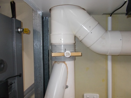
Surprisingly, it's almost as quick to operate as the other blast gates, it works so well and takes up so little room that I'm tempted to leave it and not build something better, although I guess I should make a proper insert to use when the gate is open and keep the inside wall of the 150mm pipe smooth. Wonder how much difference it makes with that sealed 0.97mm slot in the side when using that crude cover / sealing ring?
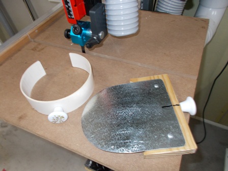
BTW, This is the fastest blast gate I have made, the metal slide insert was cut with tin snips and cleaned up for a perfect fit on the bench sander, took me all of 20 minutes, as the band saw was out of action at the time, I used a Japanese pull saw to cut the PCV pipe, these things go through PVC pipe like a knife through butter, and dead straight cuts every time. This is so small and neat that I may replace some of the timber units I made with these.
Slot cut in couipler.
Blast gate close slide plate, and gate open sealing ring.
Below: Blast gate closed. Last photo, Blast gate open.
-
22nd April 2017, 09:41 PM #24
 GOLD MEMBER
- Join Date
- Dec 2003
- Location
- lower eyre peninsular
- Age
- 74
- Posts
- 3,580
Haven't read all of this but instead of PVC or MDF etc most advertising signs are done on a plastic composite sheet with aluminium cover both sides. they always have scraps left over, or you can always recycle a used sign
 I would love to grow my own food, but I can not find bacon seeds
-
23rd April 2017, 02:17 AM #25
.
- Join Date
- Feb 2006
- Location
- Perth
- Posts
- 27,788
After making some 14 blast gates in Al for the mens shed and having some then service for ~4 months I would be more careful about using Al on Al. Originally Posted by Tonto
-
25th April 2017, 02:59 PM #26
Senior Member
- Join Date
- Mar 2012
- Location
- South Gippsland
- Age
- 58
- Posts
- 103
I've just completed some 150mm blast gates. The black outer bits are 19 mm form ply, the inner part is 6mm ply. The flanges are screwed and siliconed to the board.
IMG_0493.jpgIMG_0494.jpg
-
25th April 2017, 04:58 PM #27
.
- Join Date
- Feb 2006
- Location
- Perth
- Posts
- 27,788
Now that you have your BMH setup working you can make your own 150mm flanges as well! Originally Posted by arniew
-
24th May 2017, 01:51 PM #28
.
- Join Date
- Feb 2006
- Location
- Perth
- Posts
- 27,788
A couple of new 100 mm gates made out of PVC left overs from cutting out the internals of the 150 mm gates.
Note the use of small wooden balls as stops.
The gate (#1) and flexy behind the gate for the TS gate (#2) acts as a general vac line for the bench behind the TS and an extraction line for the router fence. Originally I used the same flexy for the TS to do the other tasks but having a specifically shorter length of flexy for the TS guard has made a big difference.
Gates.jpg
That makes 6 x 100 mm gates and 9 x 150 mm gates for a total of 15 gates.
-
3rd July 2017, 09:15 PM #29
Woodworking mechanic
- Join Date
- Jan 2014
- Location
- Sydney Upper North Shore
- Posts
- 4,469
Blast gate position
I have recently added a connection for my thicknesser. The question is, should I move the existing blast gate for the table saw from position "A" to position "B".
IMG_0746.jpg
-
4th July 2017, 11:20 AM #30
.
- Join Date
- Feb 2006
- Location
- Perth
- Posts
- 27,788
Correct - straight though flow is best. This is why those plastic gates from WW shops are rubbish. Because they go inside 100mm ducting, where they don't fit all that well anyway, they are 94 mm ID so the generate a 5 mm step that increases turbulence and this restricts the flow. Originally Posted by jmk89
I have posted the picture below before somewhere.
The blue lines show glue joins
The LHS shows one side of the cross section of a female gate where a treaded coupler is incorporated into gate body. i.e. cut coupler in half
The yellow ducting slides into, and up, to and level with the (red) slider or rocker.
This requires some fenagling when installing because you don't want the incoming pipe to hit the slider or leave a gap.
The RHS shows a male gate where a piece of ducting is permanently glued into the gate body and connected to the ducting by joiner junctions on either side of the gate.
This is much easier because I make the top and bottom halves separately and the glue the pipe in place slightly past the opening and then sand the whole thing flat on a belt sander.
Most of my initial gates are female gates but all my latter ones have been male gates
Screen Shot 2017-07-04 at 8.11.51 AM.png


 Reply With Quote
Similar Threads
-
Blast gate positionsi
By Dez Built in forum DUST EXTRACTIONReplies: 7Last Post: 3rd July 2016, 09:23 PM -
Blast gate position and three 4" outlets from one 6"
By ozhunter in forum DUST EXTRACTIONReplies: 19Last Post: 29th January 2014, 03:11 AM -
Combining a wye with a blast gate
By zelk in forum DUST EXTRACTIONReplies: 4Last Post: 18th January 2010, 09:55 AM -
Blast gate with 100% efficiency
By Wongo in forum HINTS & TIPSReplies: 10Last Post: 30th June 2005, 11:45 PM -
Blast Gate
By ozwinner in forum DUST EXTRACTIONReplies: 5Last Post: 9th May 2004, 07:12 PM
