

 Thanks: 0
 Likes: 0
 Needs Pictures: 0
 Picture(s) thanks: 0
Results 1 to 15 of 173
Thread: Building a Navigator yawl
-
4th April 2010, 06:20 PM #1
 SENIOR MEMBER


- Join Date
- Oct 2008
- Location
- Victoria
- Age
- 71
- Posts
- 631
 Building a Navigator yawl
Well, you'd have to be nuts to put two builds up for scrutiny, come to think of it, you'd have to be nuts to build two boats.
Just as life was getting back to normal, with discretionary time being taken up with normal, domestic and lifestyle sorts of things; no great urgency to get up to the shed on week-end mornings, longer walks with wife and dog, the occasional sail in a boat that felt very nice under my backside, work bubbling along, no epoxied clothes and fingers and shoes, workshop mess less and less of an issue......I went and spoilt it all by having a sort of revelation.
Since way before I built the Waller, I had a growing range and list of potential builds which could be good for certain situations/eventualities/rationalisations, and as this list grew the Waller came out on top as the one most likely to be best for the biggest number of my family under most circumstances. But the next one was always evident in my continued research.
Some of that took the form of some great exploratory thinking with a particular boat, but as this progressed it became obvious to me one night in a flash, that all of this searching seemed aimed at the production of something that could do what the navigator has been doing quite happily for years. Well, this was both liberating and frustrating.
Next day plans were ordered from Duck Flat in SA (because previous attempts to talk to the source had come to nil) and they arrived the following day. You can't beat that for service. That week-end some scraps of 9mm ply left over from the last build were already converted into bulkheads and I had to face the horrible truth that I had started again.
I'm not aiming for a masterpiece here. I want it to be beautiful and serviceable and as solid as a brick dunny, but please don't be disappointed with this thread if you see a bloke sometimes cutting corners and working a bit impatiently. Except on violins, that is what he does.
I hope this thread is worthwhile for a few of us, and not just a diary of my work. This is a boat that has given a lot of pleasure to many ordinary folks, and this ordinary folk wants to see how it looks from the working end.
-
4th April 2010 06:20 PM # ADSGoogle Adsense Advertisement
- Join Date
- Always
- Location
- Advertising world
- Age
- 2010
- Posts
- Many
-
4th April 2010, 11:12 PM #2
SENIOR MEMBER
- Join Date
- Oct 2008
- Location
- Victoria
- Age
- 71
- Posts
- 631
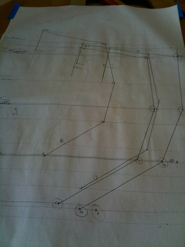
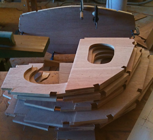
Because the plans for bulkheads (and most parts) are given in 1:5 scale drawings, and because many of these bits are fabricated from several pieces, I found it wise and helpful to 'loft' these parts full sized and spaced against a large board 'centreline'. Assuming that the given dimensions are correct, this enables me to test the total and half widths before and after assembly of the components.
I know from setting the necks in musical instruments that a tiny change in the angle of a joint can become a large error when projected out along a long arm or 'lever', and even with the most careful clamping, these joints will creep a little given half a chance. The same drawings then enable the glued up bulkhead to be tested for width and position, and maybe 'carressed' or finessed into position before assembly. Even given all of that, the slots cut for stringers will need to be angled and adjusted to allow the stringers to take up a fair curve.
Here bulkhead 3 in the rough is tested against a centreline to make sure the widths are as designed.
-
4th April 2010, 11:27 PM #3
AJ
- Join Date
- Jun 2007
- Location
- Aberfoyle Park SA
- Age
- 63
- Posts
- 1,787
Looks like you are indulging in a spot of 'real' boat-building with the lofting & etc Rob.
Will follow with interest. You've already done what would take me 6 months to do.
And incorporated a heap of cross-checking of dimensions in the process.
AJ
-
5th April 2010, 11:37 AM #4
SENIOR MEMBER
- Join Date
- Oct 2008
- Location
- Victoria
- Age
- 71
- Posts
- 631
Hi AJ, thanks. Not real lofting though, because the plans don't include a table of off-sets, you can only scale up the half-widths to full size. For beginners it would have been really useful to have full sized outlines of each bulkhead half width drawn with a common centreline, on a single sheet of paper. Never mind. Originally Posted by b.o.a.t.

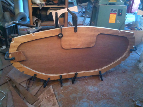
The transom doublers have been fitted oversized, and the transom skin has not got notches for the stringers. The doublers are left oversized to allow for the 'flare' of the hull going forward.
Look what I've done to my swept concrete floor already.
-
5th April 2010, 12:09 PM #5
Senior Member
- Join Date
- Nov 2007
- Location
- Fremantle
- Age
- 56
- Posts
- 125
Wow, you're off to a flying start already. Making the transom doublers over-sized is a great idea, it'll save you a lot of epoxy filling those gaps later on. I'm really looking forward to see this build through to the end.
Good work!
Mick
-
5th April 2010, 12:09 PM #6
Grumpy old Bugga
- Join Date
- May 2003
- Location
- South Oz, the big smokey bit in the middle
- Age
- 67
- Posts
- 4,377
Gawd, you're bringing back nightmares mate

Do you have one of them Japanese style razor saws? I bought one recently and was amazed at how it allowed you to shape and cut things like your stringer notches. In my case, it was fitting the side arms to the skiff and I found that not only was I able to cut right to a line, I could carve a thin sliver or wedge off the bit to make it fit - sometimes really fine stuff that you'd norrmally do with sandpaper or a file. With all the notches you'll be fiddling with, I'd suggest a good razor saw could become your most beloved tool
Leaving bits oversized is a good trick too. I did it on the skiff in places, though you may find as you start final shaping that you're marking things out again and have other 'issues'. It's a bit of a two edged sword - I found it led to more mucking about but can't remember the exact problems now but I think you'll be more satisfied with the result than just leaving a gap and filling it with pox.
Richard
-
5th April 2010, 09:24 PM #7
SENIOR MEMBER
- Join Date
- Oct 2008
- Location
- Victoria
- Age
- 71
- Posts
- 631
Helpful replies thanks Mick and Richard. I'm keeping an eye on your photo pages Mick, to find evidence of your recent progress- it must be close now.
Richard, it's funny, I've used Japanese saws but don't have one- I have a couple of lovely dovetail saws that have a fine kerf, so I've never sort of got around to buying the Japanese type. The pull action does make very good sense and I probably will if I see one when I'm in the mood to open the wallet.
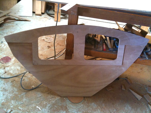
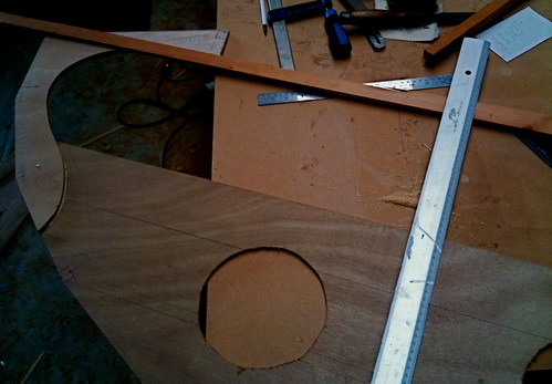
Bulkhead 2 with doublers around hatches and under deck. I have two hatches, one each side of centre because in the Yawl rig the mast is stepped aft of this bulkhead and a central hatch would be obscured by the mast.
-
7th April 2010, 11:15 AM #8
SENIOR MEMBER
- Join Date
- Oct 2008
- Location
- Victoria
- Age
- 71
- Posts
- 631
starting the stem
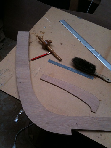
Here the central lamination of the stem has been drawn up and is being shaped. A thin very flexible batten was used to fair the curves between John's co-ordinates on the drawing. This stem is an interesting shape; neither plumb nor particularly raked and he shows it with a couple of mm 'lean back' in the top 80mm or so. I cut it as drawn.
This central lamination will be used as a template to shape the two doublers.
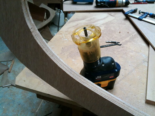 #
#
The three laminations are temp screwed together and the one closest is being taken down to the template's shape. The straight bit with bearing is visible in the router. Didn't bother to plug in the big router for this job, the little cordless is up to a job of this size if the batteries are full.
-
7th April 2010, 12:15 PM #9
GOLD MEMBER
- Join Date
- Mar 2007
- Location
- Adelaide
- Posts
- 2,139
Man I'll have to get a move on you will have yours finished before I even start.

Nice timmer BTW
-
7th April 2010, 12:22 PM #10
SENIOR MEMBER
- Join Date
- Oct 2008
- Location
- Victoria
- Age
- 71
- Posts
- 631
You mean Coquina? You wouldn't want to hurry that...

-
7th April 2010, 12:26 PM #11
Grumpy old Bugga
- Join Date
- May 2003
- Location
- South Oz, the big smokey bit in the middle
- Age
- 67
- Posts
- 4,377
But you're not building one, you're building Coquina Originally Posted by m2c1Iw
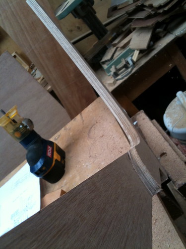
It's not obvious in the photo Rob, so am I right in assuming you've got your router set so the guide bearing runs up the middle sheet while just cutting the outer?
Neat solution to the problem, much better than gluing the three together and then trying to shape them all to a pencil line.
I really like my trimmer router (mine has a tail ie, not cordless), there are so many jobs you can do with them ... and they cut fantastic holes for inspection ports.
Richard
-
7th April 2010, 12:38 PM #12
SENIOR MEMBER
- Join Date
- Oct 2008
- Location
- Victoria
- Age
- 71
- Posts
- 631
Yep, although I have the two doublers on the near side of the 'central' ie longer lamination so that the template is furthest from the router, where the bearing is, and they were cut together.
(and I confess to cutting the inspection ports on B3 with a jig saw, very roughly because the router was set up for something else at the time. But of course that unspeakable roughness will be hidden by the ports... )
)
-
7th April 2010, 12:42 PM #13
Grumpy old Bugga
- Join Date
- May 2003
- Location
- South Oz, the big smokey bit in the middle
- Age
- 67
- Posts
- 4,377
Ahh, that explains why the bit looked so long. Originally Posted by rob540
Still reckon it beats doing it by hand.
You'd be amazed how many bits I managed to round off using my router (and this from a man who loves using hand tools )
)
They also hide where the router went astray while cutting 'neat' onesunspeakable roughness will be hidden by the ports...)

Richard
-
7th April 2010, 12:47 PM #14
SENIOR MEMBER
- Join Date
- Oct 2008
- Location
- Victoria
- Age
- 71
- Posts
- 631
Absolutely. A little round-over bit dresses edges so beautifully. Originally Posted by Daddles
-
8th April 2010, 05:07 PM #15
Senior Member
- Join Date
- Nov 2007
- Location
- Fremantle
- Age
- 56
- Posts
- 125
Geeeze, you're making all of us look bad. Its good too see that you are off to a flying start. If you haven't already done so, join the John Welsford Yahoo group. Not only are there plenty of pictures available, but there is a fairly large community of people all happy to answer your questions.
Cheers
Mickj
PS - I'll upload some more pcitures of my Nav this weekend.


 Reply With Quote


Similar Threads
-
GIS Yawl
By CCBB in forum Michael Storer Wooden Boat PlansReplies: 512Last Post: 8th February 2015, 12:30 PM -
Navigator
By Resination in forum WOODTURNING - PEN TURNINGReplies: 12Last Post: 6th January 2010, 02:04 PM -
Magma Navigator
By Resination in forum WOODTURNING - PEN TURNINGReplies: 14Last Post: 30th December 2009, 12:04 PM -
Figured Pink Ivory on a Gold Navigator
By Matt88s in forum WOODTURNING - PEN TURNINGReplies: 15Last Post: 17th May 2008, 10:24 PM -
Caledonian Yawl Plans
By Donald in forum BOAT BUILDING / REPAIRINGReplies: 1Last Post: 9th February 2004, 10:10 AM
