

 Thanks: 0
 Likes:
  Needs Pictures: 0
 Picture(s) thanks: 0
Results 16 to 30 of 42
Thread: Matthias Wandel's Bandsaw
-
22nd October 2012, 09:22 PM #16
 Senior Member


- Join Date
- Nov 2011
- Location
- Riverina NSW
- Posts
- 211

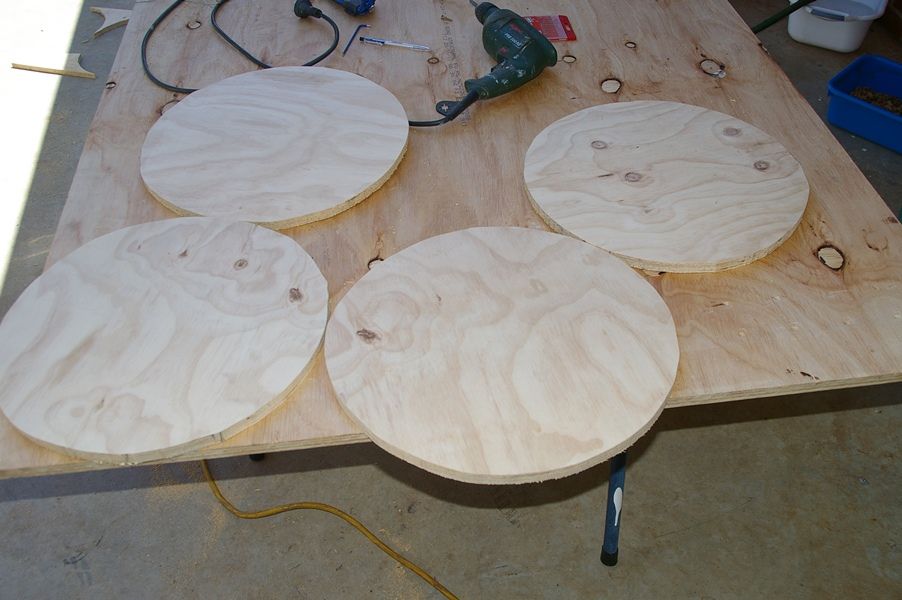
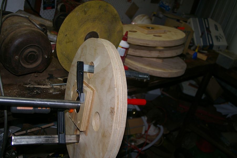
Small update. Started work on the wheels and lower mount but it was a bit of a failure. Wheels ended up too wobbly. Two things caused it besides not paying attention. I drilled 28mm holes into the centre of the wheels, I think now they should be 25mm, same as the shaft. Plus I glued and screwed the flanges too soon before making sure alignment was spot on. When I discovered my errors it was too late to remove the flanges. I removed screws and even with a mini sledge hammer the flanges wouldn't budge. Matthias adjusts them before the glue sets but within 5 to 10 mins the pva I'm using took hold. I'm going to have to start again with the wheels, might have to buy new bearings too if I can't dig the old ones out.
Running total;
$70 for 2440x1200x19mm CD exterior ply
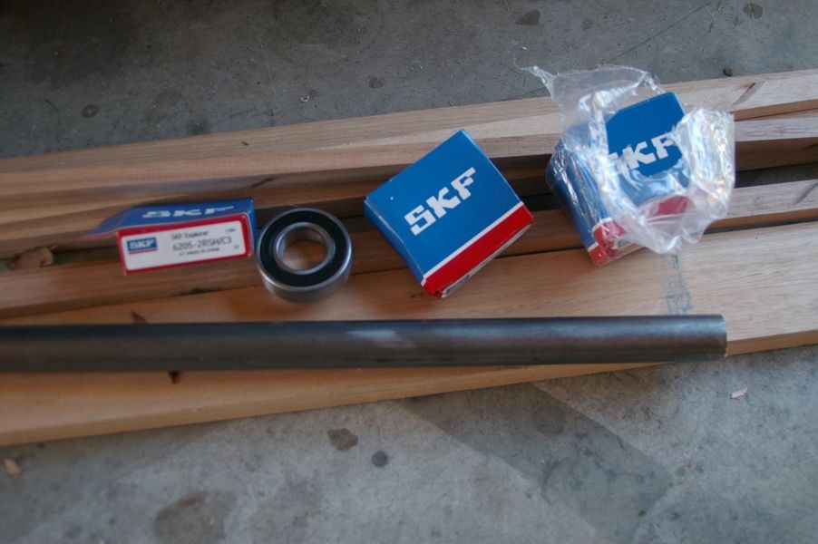
$35 for bearings, same size Matthias uses, ID 25mm OD 52mm
$12 for 25mmx1m bright steel rod for axles
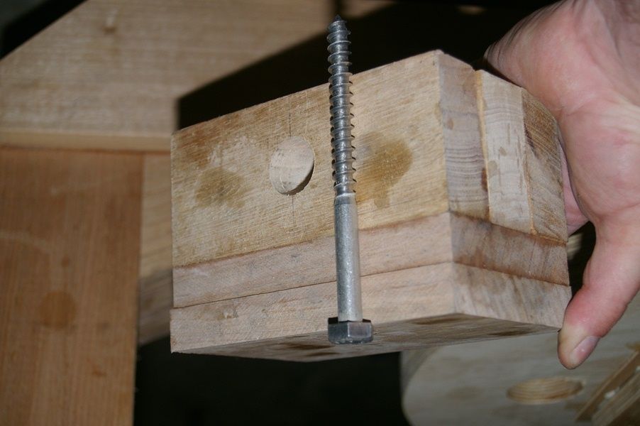
$12 for 4 coach screws for lower wheel mount, M10x130mm
total so far $330 + $129 = $459
bearings and shaft
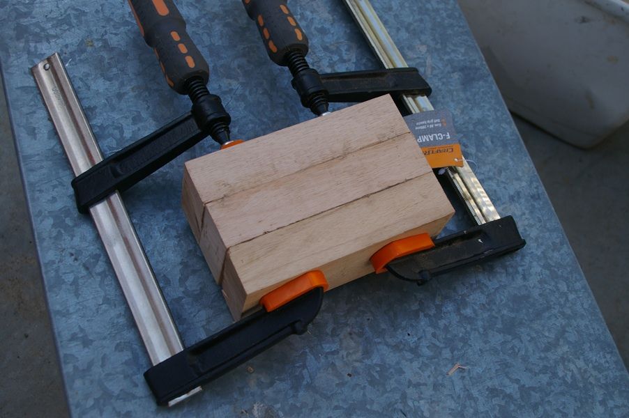
lower wheel mount made from 3x65mm pieces cut to length.
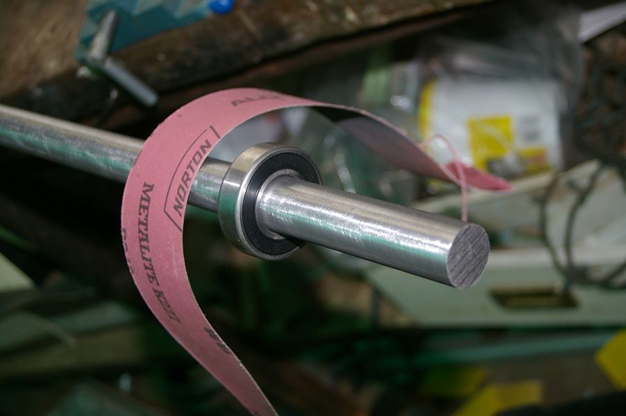
Matthias uses a wood lathe and file to smooth the axle stock. Like him I couldn't press the bearings on but I don't have a lathe of any kind. I simply used emery cloth whilst the shaft was in a vise. Worked a treat and faster than I thought it would take.
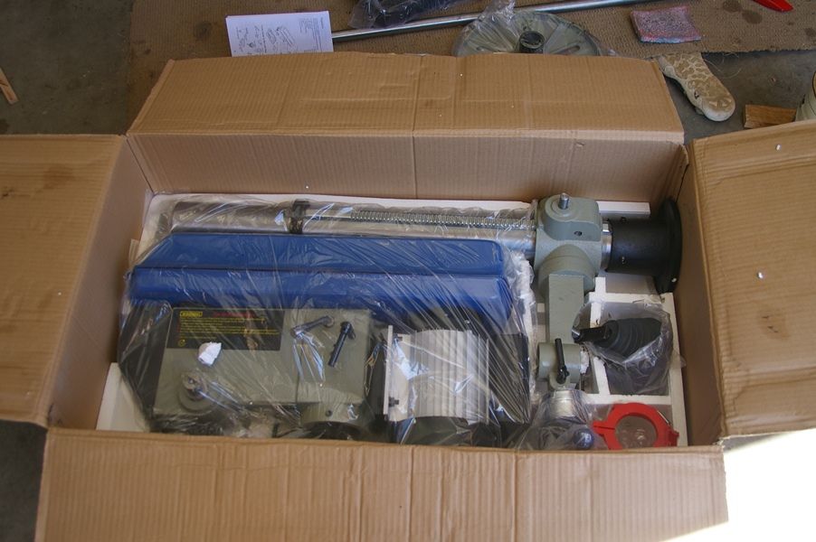
Got sidetracked, bought a bench mount drill press whilst waiting for the glue to set on the wheels. H&F D144 | SBD-25A Bench Drill | machineryhouse.com.au I bought it locally for $449, H&F have it at $363 but there's $90 shipping so pretty much same price.
Bearings in flanges. I thought things were cruising along but they went downhill a bit from here and I didn't take any more photos. Might try on emore time tomorrow to sort this out, if not it'll be another couple of weeks before I can try again. I am starting to doubt my abilities after today
-
22nd October 2012 09:22 PM # ADSGoogle Adsense Advertisement
- Join Date
- Always
- Location
- Advertising world
- Posts
- Many
-
22nd October 2012, 09:57 PM #17
Novice
- Join Date
- Sep 2012
- Location
- Jerrabomberra, NSW
- Posts
- 14
Just read through the thread. Really interesting build and looking forward to watching this as it develops.
Regards,
Peter
-
23rd October 2012, 03:00 AM #18
Senior Member
- Join Date
- Nov 2011
- Location
- Riverina NSW
- Posts
- 211
Thanks Peter, by the end of the day I was thinking I should've just bought one,
however, spirits are up again. So it's nearly 3am and I finally found out what I did wrong. I'm rereading over and over the instructions, studying his pics and the google sketchup details and sure enough I found the answers in black and white in the instructions for wheels. The wheel holes are 28mm after all but he only puts one flange on permanently, lined up by sight, like what I did. But what I didn't do was drill the four outer holes in the wheels to allow clamps to loosely hold the second flange until the wheel was trued and bearings lined up. Pretty simple really but sometimes these things don't seem that way till you make the mistake. Anyhow, next attempt I'll clamp the second flange tight at that point when there's no runout on the wheels, put a couple of screws in to act as locating pins, remove flange, apply glue then screw and clamp.
-
23rd October 2012, 09:58 PM #19
Senior Member
- Join Date
- Nov 2011
- Location
- Riverina NSW
- Posts
- 211
Success with the wheels
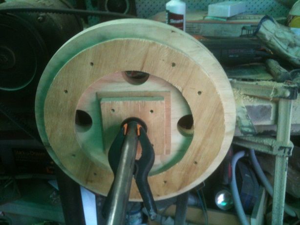
 Pretty much done as per instructions or as in last post and visible runout is negligible. It took no time at all to get the second lot of bearings on and the wheels slide on the shaft easily, unlike yesterdays warped wheels
A couple things different to yesterday worth mentioning.
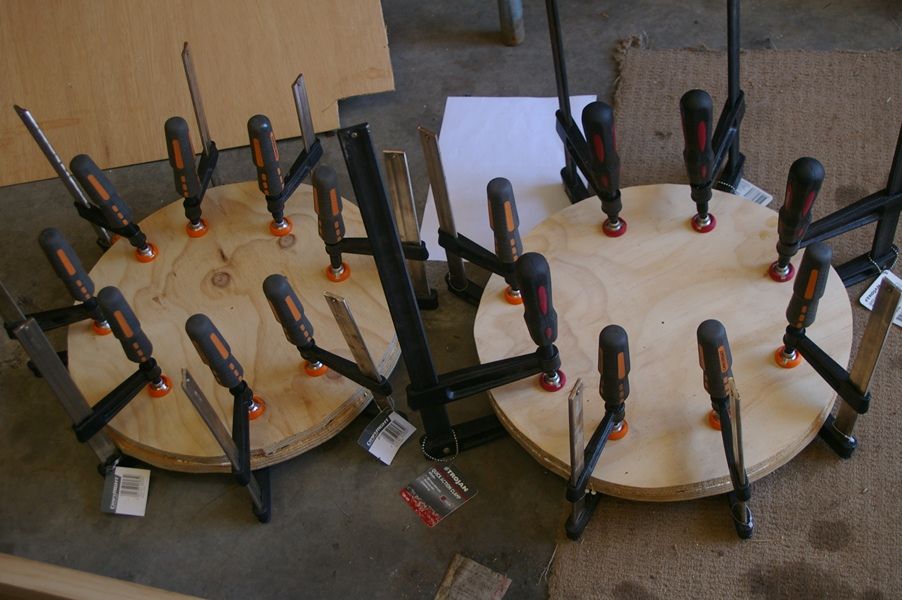
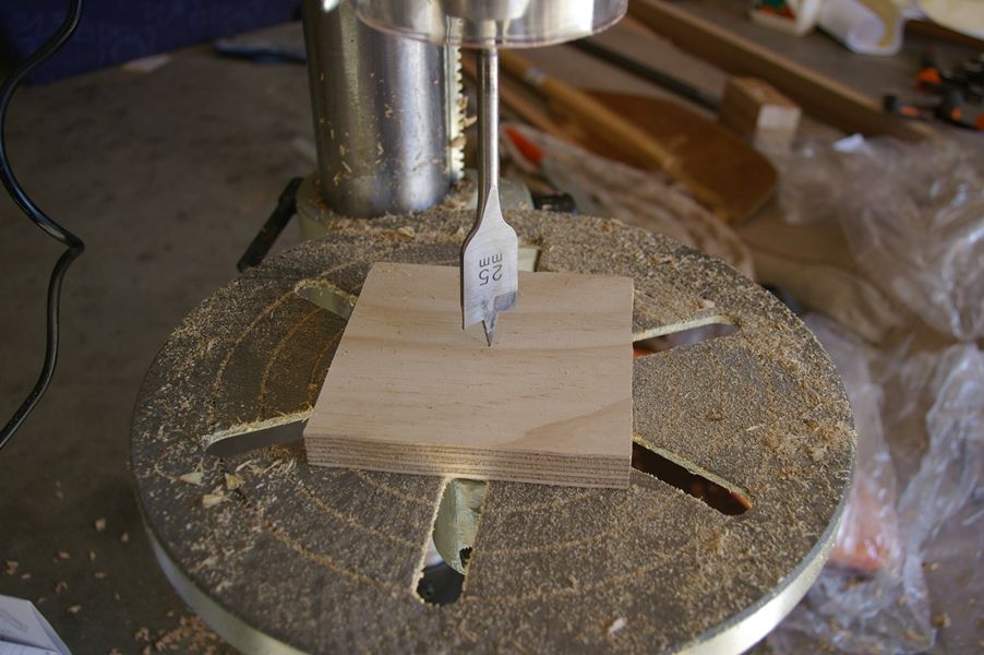
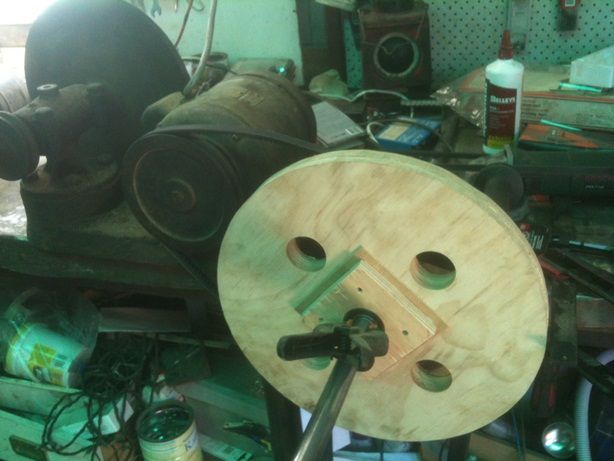
The 52mm hole for bearing flanges was done with a 51mm holesaw. With a bit of chuck wobble in the drill press the holes turned out perfect. Never thought chuck wobble could be so useful. Yesterday I used a 38mm spade bit then a router bit in the dril press to open the hole to a traced line indicating the 52mm OD bearings. It worked too but today the holesaw did a better cleaner job of it.
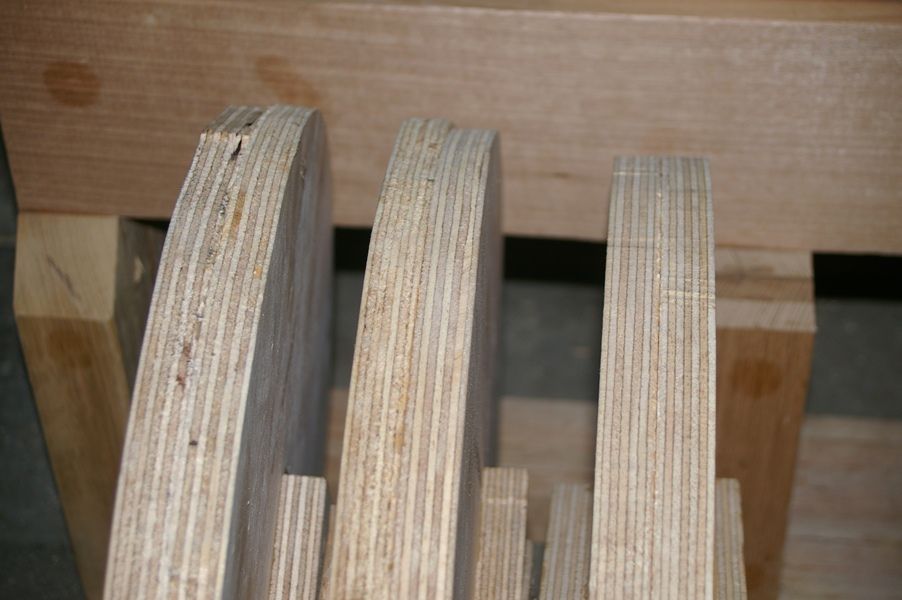
I was also easier on the jigsaw today. Yesterday I ripped around the wheel circles expecting that I could easily true them down to a perfect circle. But way too much material to remove. Today's wheels are a little eccentric but otherwise will need very little machining.
The four holes in each wheel were done with the 51mm holesaw too. The recommended 40mm holes were too small for my clamps.
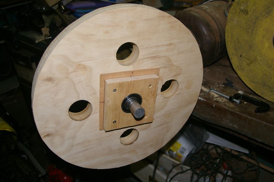
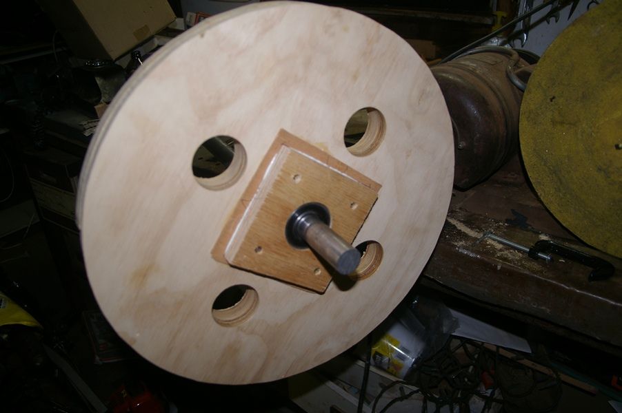
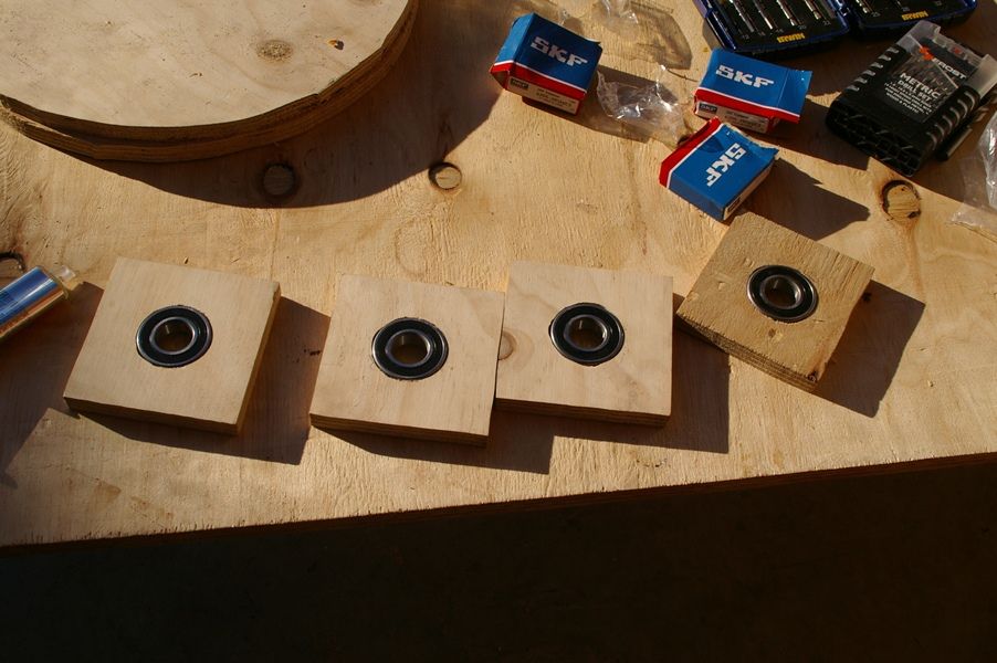
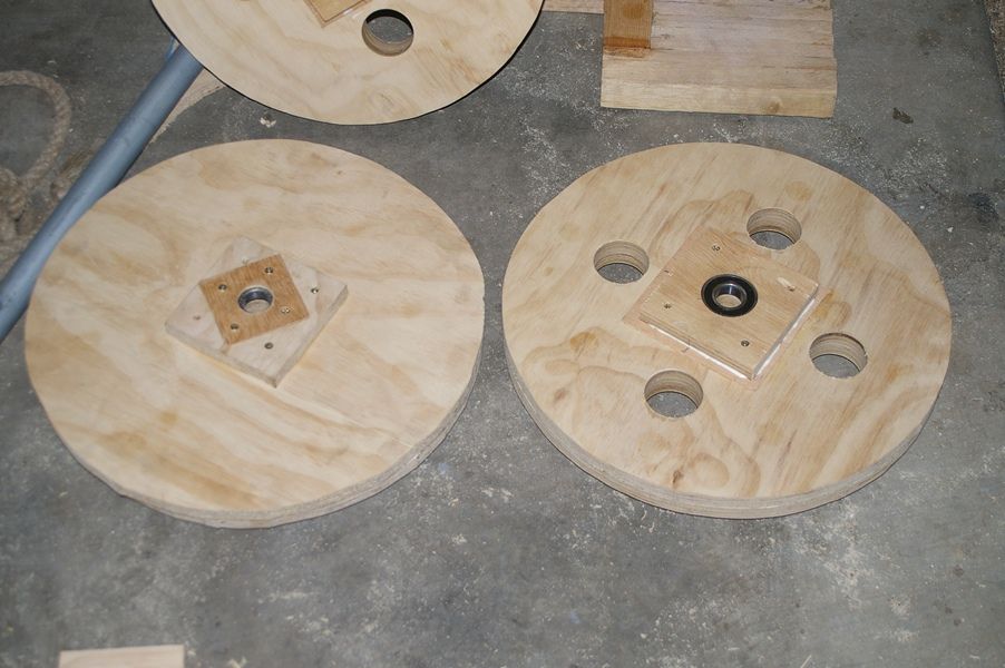
Old on the left, new on the right. I experimented yesterday using 3mm ply as cover plates over the bearings. They worked alright but I thought there might be an issue with using spacers if and when needed.
So today I went back to how it's supposed to be done, though I've used 17mm ply rather than 12mm for the flanges.
I discovered my lower wheel mount was too small so had to add a couple of pieces of wood as shown to thicken it up. It wont matter the axle will be a little closer to the frame.
The difference it makes when you take your time on the jigsaw chasing that circle.
-
24th October 2012, 06:23 PM #20
Senior Member
- Join Date
- Dec 2011
- Location
- Deception Bay Qld
- Posts
- 213
It's progressing along nicely Canoath i would say you will have a few more hurdles to jump before your done and if they are a bit high go and see what's in the beer fridge, it works for me.
-
30th October 2012, 12:46 AM #21
Senior Member
- Join Date
- Nov 2011
- Location
- Riverina NSW
- Posts
- 211
Maaaan I just lost a huge post as I was adding vids. I was gonna say whitey, I totally agree and 3 beers were missing today from the fridge, till I lost that post, now it's 4 beers missing.
So here's an abridged version of what I typed.
Today I bought some more tas oak for upper wheel mount, bolt for tensioner, a pack of eight skateboard bearings and a 1450mm v belt.
$28
$5
$24
$22
+459 = $538
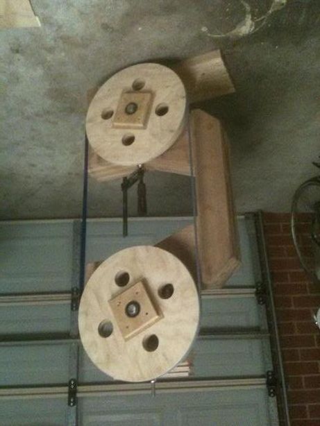
My biggest fear was worrying how shaping and mounting the wheels was going to work out. And once fitted, whether everything would go pear shaped but it's worked out fine.
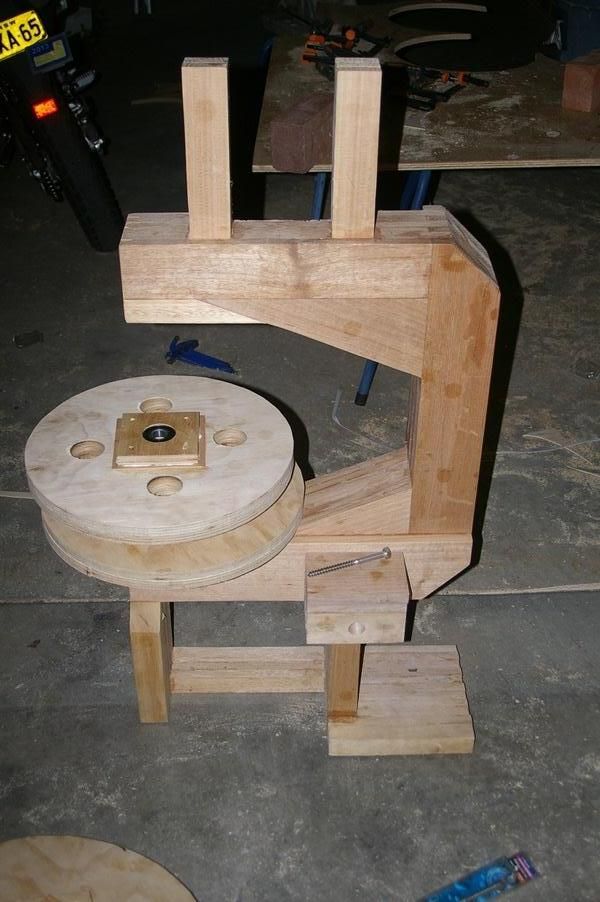
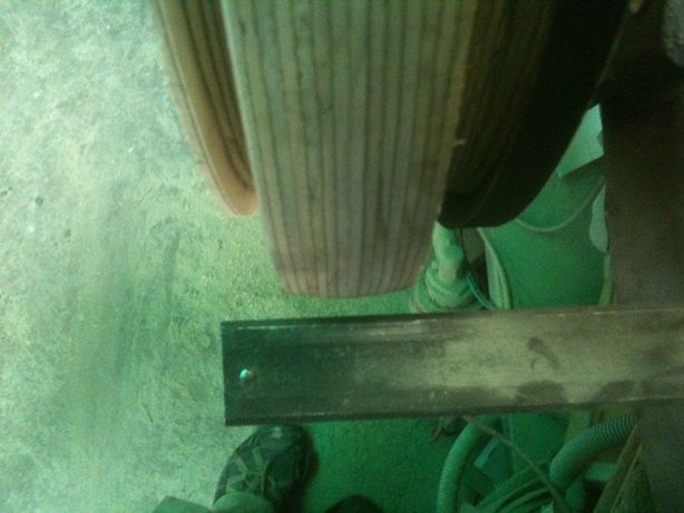
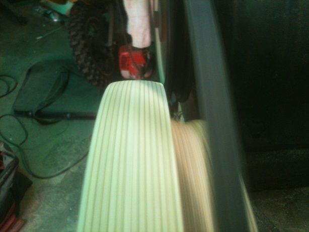
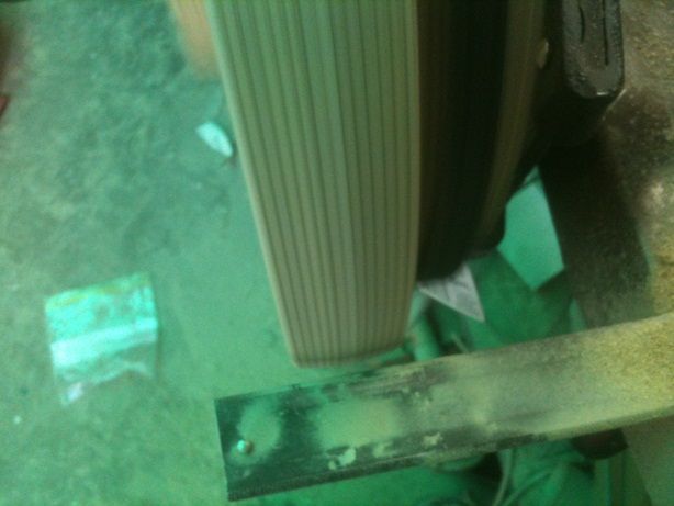
The motor I used to spin up the wheels to allow shaping and truing is an old shearer's grinder/sander for combs and cutters. A heavy unit, it's a struggle to lift and needs a hand to start turning but once up to speed it was fine, maintaining speed whilst the wheels were shaped. I used ordingary chisels, 12mm to reduce circumference and shape crowns, plus a 6mm chisel to cut the drive pulley shape. The temporary wheel was rough cut from one of the original wheel attempts and its groove for the v belt was roughly cut using a 5" grinder.
Short video showing motor start up and both wheels' profiles.
Some pics of the two wheels after shaping.
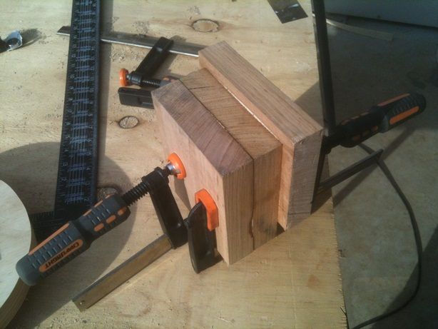
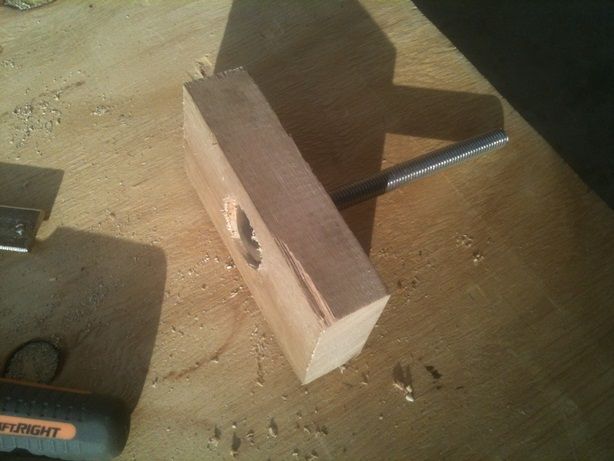
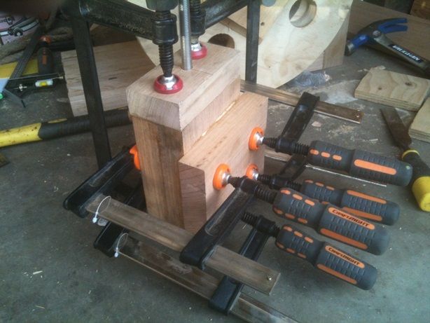
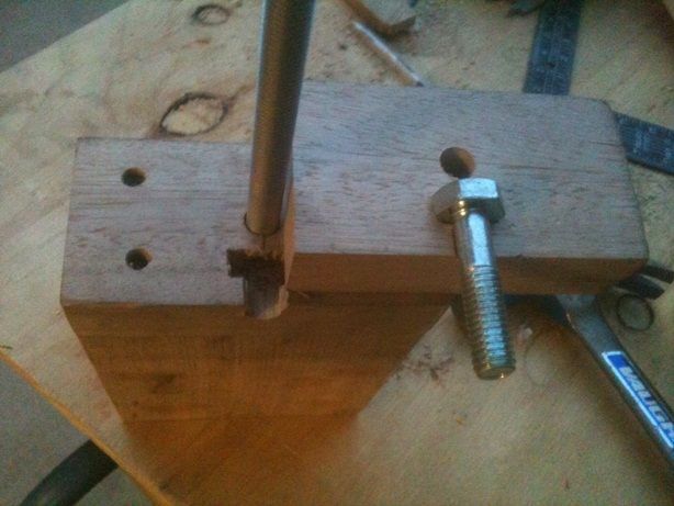
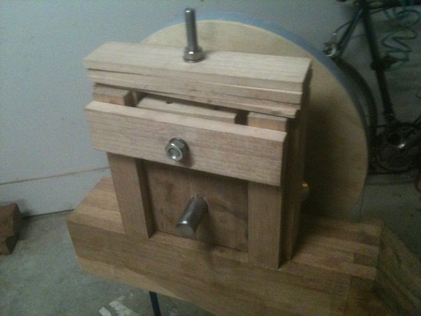
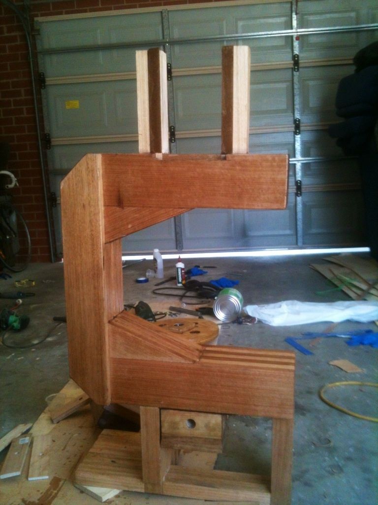
I did something way different for the top mount. I looked again and again at Matthias' box frame and thought there's no way I'm going to be able to do it justice.
I saw his 14" bsaw mill a while back and referred back to it for inspiration and I ended up slapping together bits of timber to make a big lump of wood that ended up as the top mount. 135mm wide pieces make up the bulk and fits snug between the uprights with a little planing and sanding. The bulk of it stops it twisting too and the tensioner works without causing the block to bind. It's so simple and worked out really well so far but looking forward to put a real test load on there.
Still need to permanently attach the lower mount with a little shimming but here are the wheels turning in unison for the first time.
Just using inverted pvc tape at the moment but it was good to see the tracking adjustments in action.
-
30th October 2012, 10:01 AM #22
Senior Member
- Join Date
- Sep 2010
- Location
- Melbourne
- Posts
- 298
It's looking good so far!

And don't worry about false starts and dead-ends; I had to completely remake one wheel, and used coke cans to shim my axles.
It looks to be running true on the wheels too.
-
31st October 2012, 02:41 PM #23
Senior Member
- Join Date
- Nov 2011
- Location
- Riverina NSW
- Posts
- 211
Thanks Michael. I'm feeling much more confident after getting the wheels right, and moreso now that the bottom block is permanently attached and shimmed to align the lower axel perpendicular to the frame. Beforhand the lower wheel tilted backward and although the tape tracked well, it wasn't tracking parallel to the frame. But now it is and I'm very happy with it. I think I got lucky with the wheels seem to be spinning in the same plane. I spent ages finding the right amount of shim and sideways alignment needed no adjustment which I was stoked about.
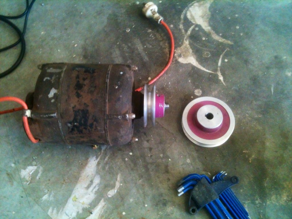
I think you said earlier about using one of my spare 1/3hp motors just to get it up and running and that's what I'm going to do until I get a decent motor.
Getting a blade hasn't been easy. The 105"/2667mm blade just isn't available locally, though I've got a local firm that supplies
sizes above and below, chasing one up. In the meantime I've got one coming from carbatec, though theirs are 2680mm which will fit.
Carbatec and Timbecon are the only two online stores that I've come across that offer blades for "14in bsaws with riser kits" that fit this 16in bsaw.
The only other thing I've done is coat everything in epoxy with two coats. Not much else I can do now till that's completely set.
Next update, next week hopefully will be motor mounting with blade running and blade guides.
Last edited by Canoath; 31st October 2012 at 04:26 PM. Reason: Corrected some detail
-
6th November 2012, 12:46 AM #24
Senior Member
- Join Date
- Nov 2011
- Location
- Riverina NSW
- Posts
- 211
I wasn't going to do any work on the bsaw till Wednesday or Thrusday but when the local guy said my blade arrived and work rang to say a packaged arrived (second bsaw blade from carbatec) I had to try them out. Also bought my first japanese saw from carbatec to make most of the postage. Man those things are good, I can see myself getting more.
$538+
$21 bsaw blade, 6tpi 10 x 2680mm
$17 11 x 1225mm v belt
$20 pulley
$12 various washers, spacers screws and a couple of bolts
$16 14" inner tubes
=$624
The sundries and mistakes makes the real total a bit more ofcourse. Some include a second pulley I probably wont use for $20, around $40 on two v belts that were too short due to miscalculations on my part, but I'll keep em. The first bsaw blade that's 4tpi 13 x 2665mm cost $50 and is too short. I shaved a few mm under the top mount to try and get it to fit but it wouldn't hop on. I could persevere and keep slicing off mm from the bottom of the top mount but for the moment I'll leave it. The 2680mm are a common size for a brand bsaw that carbatec sell and they stock a bunch of different blades to suit. I also wasted around $27 on inner tubes. I mistakenly bought two 16" thorn proof tubes at first. Too bulky I thought but may revisit them one day. A normal 14" tube split in two whilst trying to stretch it over the bottom wheel and when I went to buy a replacement I once again mistakenly got a thorn proof tube but at least 14". I used it on the bottom and it's fine, less bulky than the 16" tubes.
The only advice I'd offer is to space out the drive pulley from the bottom wheel as advised by Matthias. I neglected to, thinking it would be alright. But as v belts seem to come in either 11mm or 13mm widths, I was planning on using the later size just for percieved extra strength. But it's unuseable on mine due to the belt scraping against the inner tube. 11mm comes close but works fine. It would be good to have a little more breathing space though.
The 1/3hp motor is a pain. Although it can be pursuaded in either direction by hand just as it starts, most of the time it resists and goes the wrong way for the bsaw. Even when the wheels are spun up correctly by hand then the motor powered up, sometimes it'll kick the other way. There is a sweet spot, or a point where it is at a stall when turned on. From there a wheel can be easily pushed the correct way and the motor will come up to speed quickly. I'll have to mark the pulley and motor where that stall spot is. Also the motor's only temporarily attached at the moment with a clamp and blocking.
During the first spin up with blade tensioned, I used spring clamps on either end of both axles to keep wheels and axles in check, but there was a knock and bearing noise consistent with the wheels spinning and seemed to only come from the bottom wheel. For the second spin up I used wooden clamps on the rear of the axles and drilled, tapped and screwed retaining washers onto the front of the axles. This eliminated any abnormal noise from the wheels and/or bearings. I ran the thing for about 10 mins or so. However long it took to drink a beer basically, looking and listening for anything abnormal but all seems good. Next thing I'll do is work on the guides and temporary table so I can start cutting some of the other stuff, trunions, covers etc.
-
19th November 2012, 03:38 PM #25
New Member
- Join Date
- Nov 2012
- Location
- united kingdom
- Posts
- 2
just joined this site and yours was the first thread i read and i like it a lot well so far.
-
8th December 2012, 04:57 PM #26
Novice
- Join Date
- Oct 2011
- Location
- adelaide
- Posts
- 19
hi Canoath
i was just wondering what pulley you were using on the motor was it one supplied with the motor or did the plans show you how to make one?
thanks camel e
-
11th December 2012, 06:35 PM #27
Senior Member
- Join Date
- Nov 2011
- Location
- Riverina NSW
- Posts
- 211
Hi camele. To answer your question re motor pulley, this old motor didn't have one so I bought two separately. I didn't do any calculations for sizing, I just bought a small and large one to play with and the smaller one seems to work just fine. To buy them I just measured the motor's shaft and went to an engineering place that stocked heaps of these cast and machined aluminium pulleys of different sizes, shaft sizes, ones with keyways or grub screws etc, every combination basically. Very easy to get a pulley to suit a motor's shaft.
Somewhere in plans or on his site he does mention the speed at which the blade should travel at. Matthias provides details on what size drive pulley and motor pulley he employed for the RPM of his motor to get that speed. He also provides some detail or formula in either a video on youtube or in the plans or on his site, i forget where exactly, to work out what size motor pulley you need for the given RPM of one's motor. For my set up the drive pulley on the drive wheel is about the same size as his and my motor spins at 1425RPM but I forget what size motor pulley I have. A little too fast or too slow compared to his isn't going to matter much at all, just have to feed the wood your cutting at an appropriate speed.
I should mention though that this motor is definitely temporary. It's too dangerous so far as it needs to be stalled and nudged in the right direction just after power is switched on. Sometimes it's easy, but most of the time it over comes the stall and kicks violently in the wrong direction. I'm going to loose a finger or two, or worse.
Thanks for the coments too thecat666 and yeah it's a great site. I'm just a hack and spend way more time reading than contributing. So much useful info.
As for an update, sad to say not much. I've made the trunion support and cutout for upper blade guide support but that was early Nov. Since then the youngest got braces and the Mrs was in hospital in Canberra for a few days for some preventative maintenance, grease and oil change etc. Private health just doesn't cover as much as we hoped plus festive season costs and so on, I'm kind of skint till the new year.
-
12th December 2012, 02:13 AM #28
SENIOR MEMBER
- Join Date
- Jun 2012
- Location
- boston
- Posts
- 574
Thanks for posting! Keep us posted. This is a very interesting topic. Oh btw, where did you get the bandsaw parts?
-
12th December 2012, 09:43 AM #29
Senior Member
- Join Date
- Nov 2011
- Location
- Riverina NSW
- Posts
- 211
Hi bosox, will do, though I was a bit confused by your question thinking you may be thinking it's a kit. I just bought plans. All wooden parts are home made from scratch and bearings, blade and when I get a new motor, are basically from a local engineering shop and hardware store. I went back and had look at my first post and noticed that hyperlinks aren't really noticeable since they're not underlined nor in bold and the difference in colour is only subtle. Particularly for my dad, he's colour blind and wouldn't notice a link that the forum generates within a post unless I somehow had arrows flashing at a link. In any case, below is the link that I've underlined that goes directly to this bandsaw's page which has info and purchase details for the plans. Hope that helps.
Homemade bandsaw (version 2)
-
15th December 2012, 10:00 AM #30
Novice
- Join Date
- Oct 2011
- Location
- adelaide
- Posts
- 19
thanks i got the plans the other day i just need to have a good read.
i was given a 1hp motor the other day but the endhousing makes it a bit dificult to put a pully on it i will have to do some mods
thanks for the great wright up
camel e


 Reply With Quote
Similar Threads
-
You call that a bandsaw? This is a bandsaw
By AlexS in forum BANDSAWSReplies: 18Last Post: 21st June 2011, 12:26 AM -
Bandsaw for only the SMARTEST of Buyers -Bandsaw in Excellent Condition
By prozac in forum BANDSAWSReplies: 4Last Post: 8th June 2008, 06:23 PM -
Will Carbatec bandsaw blades fit Jet bandsaw?
By FlyingDuck in forum BANDSAWSReplies: 2Last Post: 13th May 2006, 06:32 PM -
meat bandsaw or bandsaw
By shakzool in forum BANDSAWSReplies: 9Last Post: 31st May 2005, 07:42 PM -
bandsaw mod
By trevorZ in forum BANDSAWSReplies: 2Last Post: 20th December 2003, 10:25 PM
