

 Thanks: 0
 Likes:
  Needs Pictures: 0
 Picture(s) thanks: 0
Results 16 to 30 of 105
Thread: Mit-a-mit
-
30th July 2015, 11:44 PM #16
 GOLD MEMBER


- Join Date
- Dec 2007
- Location
- Melbourne
- Posts
- 3,277

I'd like to get it in cast iron but I think it will cost a bit. More chance of casting in aluminium at a home foundry or fabricating one.
..Live a Quiet Life & Work with your Hands
-
30th July 2015 11:44 PM # ADSGoogle Adsense Advertisement
- Join Date
- Always
- Location
- Advertising world
- Posts
- Many
-
31st July 2015, 09:27 AM #17
Pink 10EE owner
- Join Date
- Aug 2008
- Location
- near Rockhampton
- Posts
- 4,304
Depending on size you could buy a piece of round cast iron bar and machine it out of that.. Originally Posted by DSEL74
 Light red, the colour of choice for the discerning man.
-
31st July 2015, 04:52 PM #18
Class Clown
- Join Date
- Jun 2008
- Location
- Bairnsdale
- Age
- 50
- Posts
- 798
Dale,
At the very very worst, you have bought yourself an extremely unique power hacksaw. Warning Disclaimer
-
31st July 2015, 06:30 PM #19
GOLD MEMBER
- Join Date
- Jul 2010
- Location
- Melbourne
- Posts
- 7,775
It would be great for heavy stock, just clamp it some where close, then move the head to get the size you want. Nice Originally Posted by matthew_g

Stuart
-
3rd August 2015, 10:05 AM #20
GOLD MEMBER
- Join Date
- Dec 2007
- Location
- Melbourne
- Posts
- 3,277
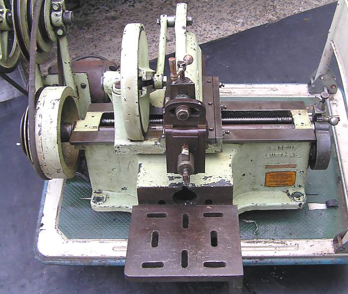
I managed to get it home. Which meant breaking it down into smaller parts to move. According to Tony's website the Perfecto which is a later usa copy weighs 130lbs (58kgs) for the motorised version. I was able to just carry the main body from a standing position lifting from the bench. When I got home I fell as it was too heavy for me to walk up the three steps into the shed. So I left it on the floor while I recovered for a few hrs. I can't lift it from the ground at all. Luckily I fell up the stairs into the doorway of the shed and now had access to the engine crane. So I very much dispute the 58kgs, as I can lift a 75kg anvil from the floor and on a good day I can pick up my 105kg anvil and put it on its stump.
The little machine is a bit more worse for wear than I had thought.
On the right handside of the front way you can see a small chip of the corner, well taht one I did when I fell the rest of it landed on me.


The arm is broken on both sides and has bars bolted to the back for reinforcing. oddly only one side has been brazed.


The bracket has a huge amount of brazing

The guard also is cracked all the way around the boss. I thought I may have done this but on inspection it was full of dirt and oil etc, so was again old damage.
 ..Live a Quiet Life & Work with your Hands
-
3rd August 2015, 10:10 AM #21
GOLD MEMBER
- Join Date
- Dec 2007
- Location
- Melbourne
- Posts
- 3,277
The automated ratchet has also be removed or partially removed to facilitate the hacksaw not moving with each stroke of it's cut.

This is the Hacksaw part that was replacing the ram.


The Table is in good nick. I think it is cast, but looks like it has original welds. I think the pattern may have been made from a steel fabrication and some of the welds can be seen in the casting which is quite interesting.


The painted over badge says war finish. (It is in a different position to the one on Tony's site.)
I'm curious about this and will try looking it up...Live a Quiet Life & Work with your Hands
-
3rd August 2015, 10:27 AM #22
GOLD MEMBER
- Join Date
- Dec 2007
- Location
- Melbourne
- Posts
- 3,277
A side note the serial number I was told probably means Build 87 3 (march) '43 (1943)
..Live a Quiet Life & Work with your Hands
-
3rd August 2015, 11:50 AM #23
GOLD MEMBER
- Join Date
- Dec 2007
- Location
- Melbourne
- Posts
- 3,277
War finish
From what I have been able to find war finish mean't lean production and of course differs from country of manufacture as deemed by their government.
WPB Limitation Order No. L-108VICTORY
Official Weekly Bulletin Of The Agencies In The Office For Emergency Management
Washington, D.C.
May 5, 1942
Volume 3, Number 18
Fancy painting and finishing of metal-working machinery banned
Fancy painting and finishing of metalworking machinery by machine tool builders were to be banned after April 30, the WPB announced April 27. Limitation Order No. L-108, effective April 27, provides that only one coat of primer or sealer may be applied to new metal-working equipment. No filler may be applied and not more than two coats of paint, enamel, or lacquer may be used. Any color other than "old machine-tool gray" for the final coat of paint is prohibited. The order was Issued, the Board stated, to reduce the time required for delivery of machine tools and to free the space now used for finishing, for more productive work.
It in some cases also meant that no aluminium was allowed to be used in manufacture and was substituted with cast iron. Some countries deemed all machines were painted the same color green as opposed to the gray above. Often bronze bushings were left out and shafts ran directly in the castings.
Another factor was the labour used was often unskilled women drawn into work as the skilled men were sent to war.
Interestingly the War finish notation was applied in various forms from a note painted on, to cast embossed latter, or simple riveted on badges to elaborate cast brass plaques. Some simply stated war finish whole other included an apology for the lack of finish due to stipulated regulations.
 ..Live a Quiet Life & Work with your Hands
-
3rd August 2015, 12:58 PM #24
GOLD MEMBER
- Join Date
- Dec 2007
- Location
- Melbourne
- Posts
- 3,277
Ratios.jpg
OK can you guys help me figure this out??
The Ram length C should be = to D+E
If B = E then the tool protrudes over the table and doesn't start at the edge reducing work envelope.
The slot G = the table length F = Stroke length.
So how do I determine the length of the drive rod H and the position of the slot G to the ram? The slot doesn't seem to be centred over the end of the ram.
Would G = the radius of the large gear driving the rod??
I can measure only D,E,F, so the rest must be calculated.
The Blue one in this photo is ends in '45 and has extra details in the casting like the go fast lines on the top of the ram, it also has extra embossed decorations on the front. It has no war finish badge. I'm not sure what the bracket is behind the ratchet??
On mine and the two others I have some photos of they have two pairs of holes, one pair at each end of the bed. I have not seen anything attached to these and wonder what they are for??
Scratch that they are oiler holes as they sit in the casting directly above the ends of the shafts..Live a Quiet Life & Work with your Hands
-
3rd August 2015, 01:37 PM #25
GOLD MEMBER
- Join Date
- Dec 2007
- Location
- Melbourne
- Posts
- 3,277
Ratchet and gears are missing.
 (
( 
Wonder if I can get size and no# teeth. If I can find some that will work from something else?? Can't make any as you need a shaper |-O..Live a Quiet Life & Work with your Hands
-
3rd August 2015, 03:46 PM #26
GOLD MEMBER
- Join Date
- May 2011
- Location
- Murray Bridge SA
- Posts
- 3,339
Thanks for showing what's left of your piece of equipment, should be a good machine, once all the bits come together. I'm sure there will be plenty of offers to help make your lost parts.

In the photo marked Ratios, where did you get the photos from? Would it be possible to ask them for the relevant details?
KrynLast edited by KBs PensNmore; 3rd August 2015 at 03:47 PM. Reason: spealing miss take
-
3rd August 2015, 06:27 PM #27
GOLD MEMBER
- Join Date
- Jul 2010
- Location
- Melbourne
- Posts
- 7,775
Hi Dale,
I dont have a tow bar but I could have helped lift it into your shed!
Stroke length is the diameter of the bull gear(minus a little)
In a perfect world ram length would be D+stroke.(but the factory one doesn't look to be nearly that long)
Stuart
-
3rd August 2015, 06:56 PM #28
Philomath in training
- Join Date
- Oct 2011
- Location
- Adelaide
- Age
- 59
- Posts
- 3,149
Measure the diameter of the gear (in inches) you have and count the number of teeth (n). It looks a bit worn but OD=(n+2)/DP; also PCD=n/DP (formula from memory) Originally Posted by DSEL74
Measure the centre to centre distance of the two stubs to the centre of the gear you have. DP is the same, so for each one n1/PCD1 = n2/PCD2. You can calculate the PCD for the small gear and using that and the centre distance calculate the other PCD. Solve for n
Michael
-
3rd August 2015, 07:14 PM #29
GOLD MEMBER
- Join Date
- Dec 2007
- Location
- Melbourne
- Posts
- 3,277
The bull gear is 220mm Dia. The saddle length D is 265mm.
I'm thinking the slot in the ram should be half the bull wheel as that is the max adjustment possible?
Also does he slot in he ram have the same centreline as the centre of the bull wheel,or doesn't it matter?
I'll measure those pins & gear. The gear that is there is attached o the bull gear. The sub below is fixed n the casting and the one to the rear is part of the feed screw. The ratchet sits on the feed screw (if you have one).
Would I be right in thinking the Bull gear drives the fixed stub and that drives the gear on the feed screw & ratchet?? Is there a reason or the fixed pin instead of having jus two gears? Change in ratio is my thought...Live a Quiet Life & Work with your Hands
-
3rd August 2015, 07:28 PM #30
Philomath in training
- Join Date
- Oct 2011
- Location
- Adelaide
- Age
- 59
- Posts
- 3,149
Hard to say - needs some better pics (or someone with vision super powers), but I'd say that the shaft is connected to the small gear, which then drives the large. On the back of the large is a cam that drives a lever. The lever pivots on the ratchet shaft and on the other end is the ratchet knob. One way the ratchet clicks over the ratchet gear, the other way the ratchet locks and so the cam on the large gear pushes on the leaver and so advances the speed.
I was mistaken in my last post in this regard as I thought the train was all three axles - the ratchet gear obviously can't mesh or it won't work
If you had a different cam profile on the back of the large gear, you could change your feed rates
Michael


