

 Thanks: 0
 Likes: 0
 Needs Pictures: 0
 Picture(s) thanks: 0
Results 31 to 45 of 48
-
7th March 2011, 03:32 AM #31
 Electrician


- Join Date
- Sep 2007
- Location
- Thailand
- Age
- 62
- Posts
- 192

The fact that you have identified the transformer as being 'crook' is a good thing.
With regard to the wiring of the new transformer, you MUST NOT connect any part of the 'Secondary Winding' to earth.
An earth wire/cable MUST be connected to the metal chassis of the transformer enclosure. This wire/cable MUST come from your switchboard (consumer unit).
There MUST NOT be any other earth cables, with the exception of below;
With regard to your load, other eath cables are connected as 'equipotential earth conductors'.I do not think there is any thrill that can go through the human heart like that felt by the inventor as he sees some creation of the brain unfolding to success... Such emotions make a man forget food, sleep, friends, love, everything. - Nikola Tesla.
-
7th March 2011 03:32 AM # ADSGoogle Adsense Advertisement
- Join Date
- Always
- Location
- Advertising world
- Age
- 2010
- Posts
- Many
-
13th March 2011, 06:58 PM #32
GOLD MEMBER
- Join Date
- Jul 2010
- Location
- Melbourne
- Posts
- 7,775
So did you get your money back?
Stuart
-
14th March 2011, 12:41 PM #33
GOLD MEMBER
- Join Date
- Jun 2008
- Location
- Victoria, Australia
- Age
- 74
- Posts
- 6,132
Hi Elkangorito, Originally Posted by elkangorito

Agreed, the wiring standards for a transformer isolated supply are clear on that point, the secondary windings have no voltage with respect to earth. But as you know, many machines imported into Australia don't meet the standards, here is the wiring diagram of the HM52 mill, I have highlighted the earth connections in colour, the green is what I believe to be correct protective earth connections. The red slashes are where I believe the connection should be broken. The blue lines are the isolated return lines from the 24v and 110v transformer secondary windings.
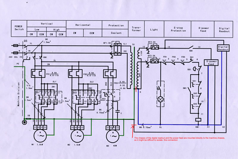
The manufacturer has just connected all the earths and the secondary "neutrals" back to mains earth...
Hope you can make sense of it. Am I correct with the modifications required to meet the standards?
Regards
Ray
-
14th March 2011, 12:57 PM #34
GOLD MEMBER
- Join Date
- Jul 2010
- Location
- Melbourne
- Posts
- 7,775
RayG
As you know I'm no expert. But,
If you move the lower red wire cut to where I have put a yellow line. Doesn't remove the potential to earth yet still allow the chassis to be earthed?
Stuart
p.s. looking at it again, why do you even need the second cut? Isn't the first cut enough?
I think I might be about to learn something new
-
14th March 2011, 01:14 PM #35
INTP
- Join Date
- May 2004
- Location
- Melbourne, Australia
- Posts
- 523
I hope someone tells one of the world's biggest computer manufacturers about this too. It seems that some laptop power supplies also earth one of the output pins.
Maybe they're wrong - but I doubt it. Their products carry approval symbols from all over the world.
-
14th March 2011, 02:03 PM #36
Pink 10EE owner
- Join Date
- Aug 2008
- Location
- near Rockhampton
- Posts
- 4,304
My transformer is wired up the same with earth wires connected to the 0 pin on the secondary side of the transformer

-
14th March 2011, 02:17 PM #37
GOLD MEMBER
- Join Date
- Jun 2008
- Location
- Victoria, Australia
- Age
- 74
- Posts
- 6,132
Hi Stuart,
I see what you mean, but my understanding is that the transformer frame must be grounded, so that any fault on the primary windings to ground should generate fault currents which trip the RCD circuits.
This is different to the secondary windings where a fault to ground won't generate any faults leading to the RCD trip. Whether you earth it or not.
Interesting, I have noticed that also, the ones with 3 pin plugs seem to carry the earth through to the DC ground.I hope someone tells one of the world's biggest computer manufacturers about this too. It seems that some laptop power supplies also earth one of the output pins.
Maybe they're wrong - but I doubt it. Their products carry approval symbols from all over the world.
I would believe that they meet the relevant standards, so maybe, the compliance is something to do with double insulation?
EDIT: I just checked a couple, and the ones with the dc ground connected to mains ground don't have the double square symbol. So I guess they aren't double insulated. The toshiba one with just two pin mains is of course double insulated and has the double square logo...
As to why they do it, I guess it's to do with EMI, or maybe grounding issues with external equipment like monitors, printers etc..
There are plenty of double insulated laptop power supplies with just the active/neutral connection, and no ground.
I recall a case years ago where a guy at the local tafe college imported computers direct from taiwan, one of the moulded iec power cables had neutral / earth reversed. Wasn't a problem he noticed, until he plugged it into an incorrectly wired power point which had active/neutral reversed. The path to ground was through the computer cpu board to the monitor. Lit up like a christmas tree with popping sound effects to match...
Regards
Ray
-
14th March 2011, 02:41 PM #38
GOLD MEMBER
- Join Date
- Jul 2010
- Location
- Melbourne
- Posts
- 7,775
Ray I agree about the transformer frame needing earthing. But once you have removed the link between the transformer frame and the secondary winding you have isolated the secondary, why then try to isolate the earth of the power feed and DRO? I agree there isnt much point earthing them in relation to the secondary of transformer, but I think earthing them might help if there is a fault in some other piece of equipment.(whould it help with static?) Originally Posted by RayG
.RC.
Mine isn't earthed. The E termail isn't lol
Stuart
-
14th March 2011, 02:52 PM #39
GOLD MEMBER
- Join Date
- Jun 2008
- Location
- Victoria, Australia
- Age
- 74
- Posts
- 6,132
Hi Stuart, Originally Posted by Stustoys
I think that's pretty much where I get to, with this whole question, if there is no voltage with respect to earth on the secondary side, it won't make any difference.....
It might in fact be difficult to isolate that connection without insulating the mounting, the power feed and dro are both mounted direct to the machine frame, which is earthed anyway. I must check to see if there is a seperate earth wire from the power feed. I know it's shown as a seperate wire on the circuit, but it could just be connected to the frame.
Regards
Ray
-
14th March 2011, 03:04 PM #40
INTP
- Join Date
- May 2004
- Location
- Melbourne, Australia
- Posts
- 523
I understand that it is "Class III" earthed. It is a new standard - and it has a new symbol (but the symbol is not in common usage yet). Originally Posted by RayG
-
14th March 2011, 03:08 PM #41
GOLD MEMBER
- Join Date
- Jul 2010
- Location
- Melbourne
- Posts
- 7,775
Agreed, but you "could" get voltage from somewhere else, say a faulty extension lead. If you had managed to isolate the DRO from earth it may now be live(but if you want to get that excited any piece of angle iron laying on the floor could have the same problem and with luck the RCD will work) Originally Posted by RayG
.RC.
Just out of interest I've just checked my mill. its secondary is isolated and neither of the earth pins on the two 110V sockets is connected.
Stuart
-
24th March 2011, 09:02 AM #42
GOLD MEMBER
- Join Date
- Jul 2006
- Location
- Adelaide
- Posts
- 2,680
Are these guys qualified to work on high voltage appliance wiring?..they need to hold the appropriate licence...i suspect that a auto elec having a licence for high voltage appliances would be very rare Originally Posted by steran50
-
24th March 2011, 10:14 AM #43
GOLD MEMBER
- Join Date
- Jul 2006
- Location
- Adelaide
- Posts
- 2,680
so which is it...to earth the 110v side or not
my trany has an earth from the chasis to the earth link.
the 0V side of both the 110v & 24V side are bridged and connected to earth.
the chasis from all accessories should have a connection to earth if I am not mistaken
Just rang a switchboard making sparky who said the secondary side can be done two ways
1. A double pole circuit breaker on both legs of the secndary and no earth from the 0v connection
or
2 A circuit breaker/fuse on the secondary side and the other side ie the neutral is earthedLast edited by eskimo; 24th March 2011 at 10:28 AM. Reason: ring a mate time
-
24th March 2011, 10:35 AM #44
GOLD MEMBER
- Join Date
- Jul 2006
- Location
- Adelaide
- Posts
- 2,680
MM just checked the wiring diag for my HM52 and it doesnt show any fuse or the like for the 110v secondary side like yours does Ray...maybe i'd better fit something Originally Posted by RayG
-
24th March 2011, 10:37 AM #45
GOLD MEMBER
- Join Date
- Jul 2010
- Location
- Melbourne
- Posts
- 7,775
Hi eskimo
The answer seems to be "depends who wired the machine".
My opinion for my machines is that it would do more harm than good.
Got a picture?
Stuart


Similar Threads
-
motor wiring diagram
By .RC. in forum METALWORK FORUMReplies: 2Last Post: 12th July 2010, 07:37 PM -
Wiring Diagram HM52
By eskimo in forum METALWORK FORUMReplies: 1Last Post: 30th May 2010, 02:15 PM -
Boats 101 - diagram of components?
By Vaughn in forum BOAT BUILDING / REPAIRINGReplies: 11Last Post: 27th April 2010, 05:19 PM -
Need wiring diagram for two switches.
By Nurgle in forum DUST EXTRACTIONReplies: 16Last Post: 10th June 2009, 09:09 PM
