

 Thanks:
  Likes:
  Needs Pictures:
  Picture(s) thanks:
Results 1 to 15 of 28
-
2nd November 2007, 11:09 AM #1
 Ox and Herdsman Vanished


- Join Date
- May 2005
- Location
- Eden Hills, South Australia
- Age
- 63
- Posts
- 3,458
 Possible method for Kintaro Yazawa's Trick Box Joint?
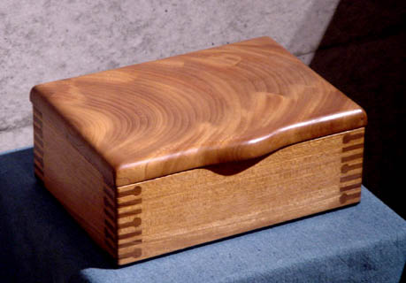
I've been playing with the 'Trick Box' of Kintaro Yazawa, which is shown here.
I believe the illustrated method is assemblable, in principle.
Pics are:- The four sides with trick-fingers cut.
- The process of sliding each blue side from the inside of the pink sides, at a diagonal.
- Two sub-assemblies complete.
- The process of sliding the two sub-assemblies together, again the blue sides slide from the inside of the pink sides, at a diagonal.
- The pink sides show the holes where the blue sides have entered, so these are covered on the inside with a piece of veneer.
- The completed sides.
Also, the box I have drawn is square, so the sides slide in at 45 degrees. Kintaro's box is rectangular; I'm assuming this can be handled by arranging the joints to slide in at the appropriate angle (not 45 degrees). I've yet to produce a drawing of this case.
Anyone care to take up the challenge of making this? It's way beyond my capabilities.Those are my principles, and if you don't like them . . . well, I have others.
-
2nd November 2007 11:09 AM # ADSGoogle Adsense Advertisement
- Join Date
- Always
- Location
- Advertising world
- Age
- 2010
- Posts
- Many
-
2nd November 2007, 12:42 PM #2
.
- Join Date
- Jul 2005
- Location
- Victoria
- Posts
- 5,215
Brilliant idea Zen
 A lot of brain power has been used to come up with that, and a fantastic set of diagrams. The only thing that stands out for me is a rebate equal to the slide-in pink bit thickness will be needed, so when it slides in all four sides are of a uniform thickness. Again well done
-
2nd November 2007, 06:36 PM #3
SENIOR MEMBER
- Join Date
- Aug 2003
- Location
- Christies Beach
- Age
- 59
- Posts
- 972
G'day Drew, excellent drawings mate, Sketchup?
Would this be feasible?
The direction of the females is rotated 90 degrees and the males are mitred, forgive the crude botching of your pic (the tiny red lines).
Remember that it is a "trick" box, the males would be very weak resulting in basically a butt joint.The secret to creativity is knowing how to hide your sources.
Albert Einstein
-
5th November 2007, 11:19 AM #4
Ox and Herdsman Vanished
- Join Date
- May 2005
- Location
- Eden Hills, South Australia
- Age
- 63
- Posts
- 3,458
Tankstand: I'm not sure of the purpose of your suggested change. Maybe we can talk about it at the barbeque on Saturday.
Lignum: agreed. I had thought about that when I was drawing it. Attached is the illustration with your recess included. (I would have attached the Sketchup file, but it's too big for the forum limits, even when compressed. )
Those are my principles, and if you don't like them . . . well, I have others.
)
Those are my principles, and if you don't like them . . . well, I have others.
-
5th November 2007, 05:48 PM #5
SENIOR MEMBER
- Join Date
- Aug 2003
- Location
- Christies Beach
- Age
- 59
- Posts
- 972
Drew, I was trying to eliminate the need for veneer as you asked! Originally Posted by Zenwood

Please find attached a rough drawing highlighting the assembly directions of your method compared to my suggestion. And note the area of yours that needs covering.
I hope this clarifies my suggestion.
See you Sunday.The secret to creativity is knowing how to hide your sources.
Albert Einstein
-
6th November 2007, 11:22 AM #6
Ox and Herdsman Vanished
- Join Date
- May 2005
- Location
- Eden Hills, South Australia
- Age
- 63
- Posts
- 3,458
Still confused. Cutting out the piece you indicated doesn't seem to offer any advantage: sliding it in from 'inside' the pink piece still needs the holes exposed on the inside, and sliding it in from the other direction doesn't work unless you make holes exposed on the ends of the straight fingers.
See you on Sunday.Those are my principles, and if you don't like them . . . well, I have others.
-
6th November 2007, 04:11 PM #7
Member
- Join Date
- Jul 2004
- Location
- Glen Iris, Vic
- Age
- 40
- Posts
- 55
I think tankstand was meaning something more like this, with the "shafts" and "holes" alignied on the other 45deg angle. I had to fudge it a bit to hide the construction, but still wasn't ale to manage it. The changes from the original design are:
- The shafts now extend past the depth of the pins, instead of all being in line
- The two parts are of different width (i.e., the front is thinner than the side by half the width of the shaft
- Both ends of the shaft are visible on the front piece (green)
Perhaps it is possible to keep the original design with this method of construction, but i can't see how to do it right now.
-
6th November 2007, 04:17 PM #8
Ox and Herdsman Vanished
- Join Date
- May 2005
- Location
- Eden Hills, South Australia
- Age
- 63
- Posts
- 3,458
One idea is to change the angle from 45 degrees, as I hinted above, which would be required if the sides of the box were different lengths (to allow the two two-side sub-assemblies to go together).
If anyone wants to play with the Sketchup file, PM me and I'll mail it to you.Those are my principles, and if you don't like them . . . well, I have others.
-
6th November 2007, 04:21 PM #9
GOLD MEMBER
- Join Date
- Dec 2004
- Location
- Northen Rivers NSW
- Age
- 57
- Posts
- 2,837
I've got no suggestions but just wanted to say;
I love you guys

You remind me of why god invented the nail and hammer


-
6th November 2007, 06:03 PM #10
Member
- Join Date
- Jul 2004
- Location
- Glen Iris, Vic
- Age
- 40
- Posts
- 55
I'm not sure if that would make a difference, besides, you should be able to assemble it as long as the shafts and pins on diagonally opposite corners are parallel no matter how long the sides/front are. Originally Posted by zenwood

Having re-read tankstands post I realised that i didn't exactly do what he suggested, i might have anpther go tomorrow.
These cad models are nice, but how would you go about cutting those pins with perfectly round shafts on them? The words "very carefully" come to mind .
.
-
6th November 2007, 06:50 PM #11
SENIOR MEMBER
- Join Date
- Aug 2003
- Location
- Christies Beach
- Age
- 59
- Posts
- 972
Well done with these drawings guys, thank you Mingus.
And sorry Drew but I did not forsee your oops senario, sure helps when things are drawn!
I'm sure with some relieving or trickery this attack method could still be possible.The secret to creativity is knowing how to hide your sources.
Albert Einstein
-
6th November 2007, 08:56 PM #12
GOLD MEMBER
- Join Date
- Jan 2006
- Location
- Bowral, NSW, Australia
- Age
- 74
- Posts
- 1,471
If what I'm about to suggest has already been said in 'sketch up' language, please forgive me.
What if the both sides were originally thicker to start with and had been cut down (like thicknessed) except for the protruding circular pins? The 2 boards slide together but the protruding pin goes further.
Carry Pine
-
6th November 2007, 09:06 PM #13
GOLD MEMBER
- Join Date
- Jan 2006
- Location
- Bowral, NSW, Australia
- Age
- 74
- Posts
- 1,471
Sorry, I was looking at mignus's 2nd drawing attempting to get the extra depth in the pin. There is no need when you look at Yazawa's box.
Zenwood, i believe has got the idea, but what about one step further and making mignus's 2nd drawing. Even the master would be proud.
CP
-
6th November 2007, 09:33 PM #14
GOLD MEMBER
- Join Date
- Mar 2007
- Location
- Adelaide
- Posts
- 2,139
Zenwood, I think your teasing us
I know my brain hurts trying to figure it out. When I look at the third pic of the masters box it appears to me that there is in fact a piece of veneer at the far end. This piece again appears to extend into the longer sides, I suggest that is why the inside top edges are rounded as much to disguise the join. It may be the the pic but the longer sides appear thinner along the length than at the joint perhaps to aid assembly.
Hence if he needs veneer there is no answer to the question you put.
Amazing sketchup BTW and well done on figuring it out, I wonder if an email requesting confirmation from the maker would be well recieved
What I still can't work out is how the round section of the joint (not sure if you call them fingers, pins or what) are shaped. I assume chisel if so the patience and skill is extaordinary.
Cheers MikeMike
"Working to a rigidly defined method of doubt and uncertainty"
-
6th November 2007, 10:13 PM #15
Ox and Herdsman Vanished
- Join Date
- May 2005
- Location
- Eden Hills, South Australia
- Age
- 63
- Posts
- 3,458
I noticed that in a WIP shot of the maker doing his paper-thin finger joints, he does marking out on adhesive tape and then sticks it onto the wood. A similar method seems possible here. Print the pattern for the outside, end, and inside cut lines, then stick the tape in place, and use a combination of coping saws, chisels, small files etc to remove the waste. Would be very long and detailed work with hand tools. Perhaps there is a special keyhole-shaped router bit, along with special holding jigs that could be used to make the fingers with rounded ends.
Those are my principles, and if you don't like them . . . well, I have others.


 Reply With Quote


Similar Threads
-
Box Joint Jig for Workcentre 2000?
By Wildberry in forum TRITON / GMCReplies: 2Last Post: 3rd December 2004, 07:13 AM -
Box joint jig
By Rocker in forum HOMEMADE TOOLS AND JIGS ETC.Replies: 2Last Post: 26th May 2004, 04:47 PM -
Box Joint Jig - Triton Router Table
By SteveI in forum HOMEMADE TOOLS AND JIGS ETC.Replies: 8Last Post: 19th April 2004, 05:39 PM -
Box joint jig
By mikmaz1 in forum HOMEMADE TOOLS AND JIGS ETC.Replies: 2Last Post: 21st September 2003, 11:33 PM -
vac box for template routing
By soundman in forum ROUTING FORUMReplies: 4Last Post: 27th July 2002, 11:56 PM
