

 Thanks: 0
 Likes: 0
 Needs Pictures: 0
 Picture(s) thanks: 0
Results 46 to 60 of 211
-
24th February 2012, 11:47 PM #46
 GOLD MEMBER


- Join Date
- Jun 2008
- Location
- Victoria, Australia
- Age
- 74
- Posts
- 6,132

Well, we uncovered the first major problem, the pin on the cross feed acme nut had broken off.
Looks like it was broken some time ago...
So the saddle has had to come off, and I'll have to make up a new pin and bore the nut to suit. If that's the only major issue, i'll be happy.
Harty, regarding the chain rollers, I'll get some pictures tomorrow of the underside of the table, and it will all make more sense.
Phil's got it, Mrs Clayton it is... delicate little innocent flower that she is...
Regards
Ray
-
24th February 2012 11:47 PM # ADSGoogle Adsense Advertisement
- Join Date
- Always
- Location
- Advertising world
- Age
- 2010
- Posts
- Many
-
25th February 2012, 12:04 AM #47
GOLD MEMBER
- Join Date
- Jun 2008
- Location
- Victoria, Australia
- Age
- 74
- Posts
- 6,132
This is the broken pin, I was referring to...
Here's the other half... as Mythbusters would say... "There's yer problem"
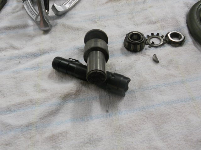
Regards
Ray
-
26th February 2012, 02:21 PM #48
GOLD MEMBER
- Join Date
- Jun 2008
- Location
- Victoria, Australia
- Age
- 74
- Posts
- 6,132
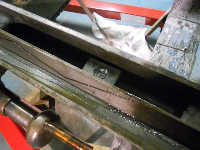
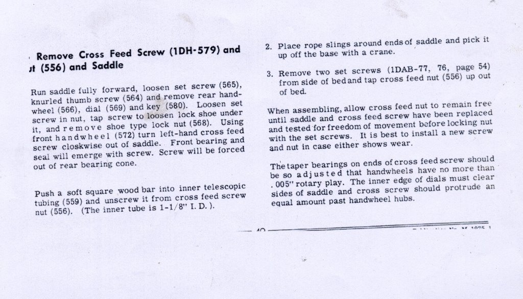
Removing the Cross Feed Nut.
This is probably a question for RC, I need to remove the cross feed nut, so I can bore it to accept a replacement pin. But I've hit a brick wall... the instructions for removal rely on the pin being intact and in place for the screw to act against and force the front bearing assembly out.. I'm a bit reluctant to force it unless I know it's going the right way.
Here's the current state of play.. the saddle is off, and upside down on work horses.
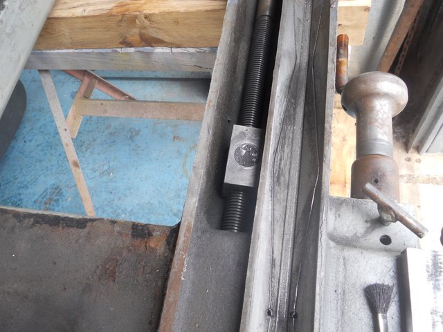
Close up of the outside end of the cross feed screw.
The other end of the cross feed screw.
The cross feed nut I want to get out..
This is how the manual says to do it, but I don't think this works if the pin is broken...
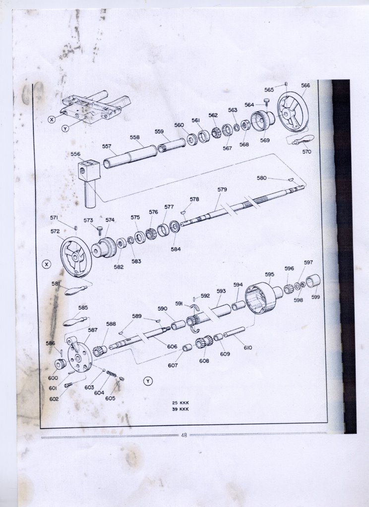
Exploded view from the manual, but I'm not sure if it's the right manual for this machine.. but at least this part looks the same..
So, the question is how to remove the screw, when the pin on the cross feed nut is broken?
Regards
Ray
-
26th February 2012, 02:34 PM #49
Pink 10EE owner
- Join Date
- Aug 2008
- Location
- near Rockhampton
- Posts
- 4,304
Mine only had a tapered roller bearing both ends, So you just remove the adjusting screws and wind it out.....
Have you worked out what the table runs on since it has no balls?Light red, the colour of choice for the discerning man.
-
26th February 2012, 03:00 PM #50
GOLD MEMBER
- Join Date
- Jun 2008
- Location
- Victoria, Australia
- Age
- 74
- Posts
- 6,132
Thanks RC, I'm making up some blocks to put against the nut for the screw to act against, and see if that works...
Here is the bottom of the table..
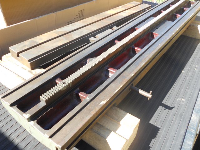
The two ball bearings run against the side of the rack, and there is a lip that stops the table from being lifted, as Stuart rightly guessed.
Although, on reflection, you could push the spring loaded bearing and move the table backwards to clear the lip and then lift it... we just slid it off the end... worked just as well.
The rollers run on the rails either side. Here's the picture I posted earlier of the rollers
So, instead of the table running on balls, it runs on the rollers. Seems simple enough..
I wonder why they did it that way though, I would have thought the point contact ball bearings would be smoother and more accurate?
Regards
Ray
-
26th February 2012, 03:11 PM #51
GOLD MEMBER
- Join Date
- Jul 2010
- Location
- Melbourne
- Posts
- 7,775
Hi Ray,
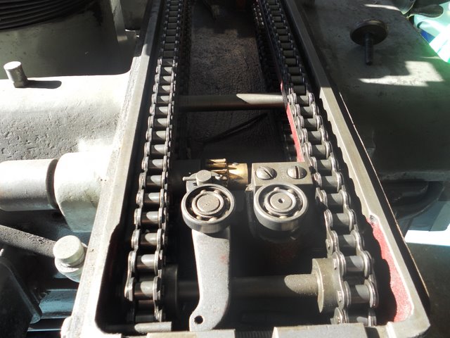
Did Josh show you the flats on the bearing?(the left bearing in the picture)
Stuart
-
26th February 2012, 03:43 PM #52
GOLD MEMBER
- Join Date
- Jun 2008
- Location
- Victoria, Australia
- Age
- 74
- Posts
- 6,132
Hi Stuart, Originally Posted by Stustoys

Yes, I'm going to replace those 4 bearings, they feel rough and lumpy, they've probably had their fair share of grinding dust over the years..
I'm thinking seriously of trying to go all cbn with the wheels, I think they cut cleaner and you don't get as much of that fine hard grit that you get with alox.
Regards
Ray
-
26th February 2012, 05:15 PM #53
GOLD MEMBER
- Join Date
- Jul 2010
- Location
- Melbourne
- Posts
- 7,775
I've been wondering how the flats got there. My guess is a little grit in the bearing so each time the table starts the bearing slides just a little(against a cast iron lap) then starts spinning as it should............ repeat 10000 times.
I guess its worth a try if these cbn wheels are as good as they say. As long as you dont end up with a smaller amount of grit the is even harder. How do you dress a cbn wheel?
Stuart
-
26th February 2012, 05:55 PM #54
GOLD MEMBER
- Join Date
- Jun 2008
- Location
- Victoria, Australia
- Age
- 74
- Posts
- 6,132
No idea... Originally Posted by Stustoys
The ones where the cbn is plated somehow onto a metal substrate, are probably not dressable, well, not without some special gear I guess...
The ones where the cbn is embedded in a resin type material, could be a possibility with a diamond dresser. For profile grinding where you need to dress a particular profile, I imagine that's how they do it?
Regards
Ray
PS Taking a break from the cross feed nut problem... Mrs Clayton has got us beat at the moment...
-
26th February 2012, 06:12 PM #55
Philomath in training
- Join Date
- Oct 2011
- Location
- Adelaide
- Age
- 59
- Posts
- 3,149
Ray,
as a temporary fix, can you weld (or braze) the stub back onto the nut? - just enough to get things out.
Michael
-
26th February 2012, 08:24 PM #56
SENIOR MEMBER
- Join Date
- Jul 2011
- Location
- Melbourne Australia
- Posts
- 1,128
Ray.
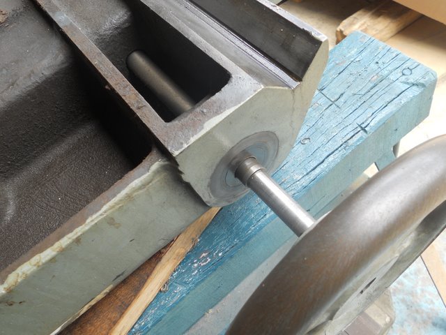
In this picture.
http://www.backsaw.net/pics/TC/DSCN1777.JPG
Those round circular unpainted bits. Is there any chance those pull out. Looking at the other side, with the tapered roller bearing, Id expect a tapered roller bearing under there with a lock nut. Try a mag base on them.
Either way the shaft goes back into the castings as the diameters are smaller out near the hand wheel. But maybe you have removed some of that all ready, try a soft face hammer, to try and knock it inwards.
I dont think that drawing is of yours, it has bearings at each end, yours clearly has both bearings at one end.
Phil.
-
26th February 2012, 08:28 PM #57
Blacksmith, Cabinetmaker, Machinist, Messmaker
- Join Date
- Dec 2011
- Location
- Canberra
- Age
- 40
- Posts
- 4,467
Ray,
Thanks for the interesting reading, i love seeing how old machines work . i like the zig zag pattern in the oil grooves in the pic of the nut your trying to remove.
I see in one of the pics your shaper is in the background, just to make the rest of us "shaperless" people even more envious!
-
26th February 2012, 08:54 PM #58
GOLD MEMBER
- Join Date
- Jun 2008
- Location
- Victoria, Australia
- Age
- 74
- Posts
- 6,132
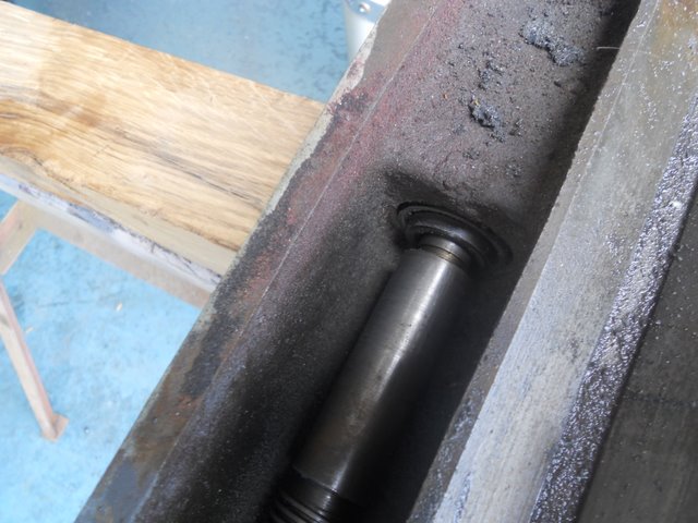
Hi Phil, Correct, both tapered roller bearings are at the one end and the sleeve between the two bearings turned out to be locked in place with a tapered pin.. you can just make it out in this picture. Originally Posted by Machtool
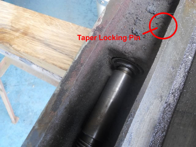
Once the pin was out, Mrs Clayton suddenly became meek and mild, instead of stubborn and abusive....
I'll take some pictures of the whole set up later..
Regards
Ray
-
26th February 2012, 08:57 PM #59
Senior Member
- Join Date
- Oct 2008
- Location
- Wimmera
- Age
- 51
- Posts
- 363
Hi Ray
for what its worth mine came out the back I locked the y axis with a clamp and and used the thread to wind out the bearings and thread which you cant do
the Front was just a bush i think no tapered bearing
it looks very similar i have attached a pick of the table bearings its not chain but it does use rollers instead of balls this was just after i picked it up so its a bit dirty
Attachment 199524
cheers
Harty
-
26th February 2012, 08:58 PM #60
Senior Member
- Join Date
- Oct 2008
- Location
- Wimmera
- Age
- 51
- Posts
- 363


Similar Threads
-
Tool and Cutter grinder
By 4-6-4 in forum METALWORK FORUMReplies: 2Last Post: 12th October 2011, 11:40 PM -
More Tool & Cutter Grinder plans
By Big Shed in forum METALWORK FORUMReplies: 2Last Post: 22nd July 2011, 09:37 PM -
tool an cutter grinder maybe???????
By tanii51 in forum METALWORK FORUMReplies: 2Last Post: 1st July 2011, 09:30 AM -
Tool and cutter grinder
By 12teethperinch in forum THE HERCUS AREAReplies: 0Last Post: 3rd November 2010, 03:49 PM -
Tool & Cutter Grinder
By graemet in forum METALWORK FORUMReplies: 14Last Post: 20th November 2009, 08:27 AM
