

 Thanks:
  Likes:
  Needs Pictures:
  Picture(s) thanks:
Results 16 to 30 of 37
Thread: Converting 3 phase star to delta
-
12th October 2012, 03:53 PM #16
 GOLD MEMBER

- Join Date
- Aug 2011
- Location
- Melbourne
- Posts
- 2,951

Hi Eskimo,
Hold off on contacting the patent office and ignore my last post regarding the RPM of the motor. I thought I was going nuts! Turns out that my optical tacho must have got a bad reading. It's still a 4 pole 1440 RPM motor. It's more like 1490 now!
No I didn't mark the location for the ends I will next time I dismantle it. In any case I think the problem was lack of care in assembly, not the location of the ends.
The motor purrs like a kitten. Only noise comes from the carrier frequency and the cooling fan. NICE!
Thanks,
Simon
-
12th October 2012 03:53 PM # ADSGoogle Adsense Advertisement
- Join Date
- Always
- Location
- Advertising world
- Posts
- Many
-
12th October 2012, 07:19 PM #17
GOLD MEMBER
- Join Date
- Aug 2011
- Location
- Melbourne
- Posts
- 2,951
Hi all,
I mentioned earlier that one problem I have with the marriage of this motor to mill mill is that the shaft on the motor is 28mm and the required shaft size is 19mm. Not normally a major problem as I would just consider turning down the shaft of the motor, after the bearing. However, what complicates this is that the motor shaft has an M8 thread tapped into the shaft.
The shaft of the motor needs to marry up with an equivalent sized female and coupled with a keyway. Turning down the shaft would leave about 5.5mm (approx) of material which as Michael points out, a general rule of thumb is at least the radius of the hole should be left. Turning the shaft down would still satisfy this requirement but as soon as I machine the keyway, I would almost break through into the inner M8 thread. So, for me this is not an option.
I could have a bet each way and bore out the hole that the shaft fits, to say 22mm and then turn the shaft down to fit but I am hesitant to modify permanently anything on the mill in case I stuff things up. I would rather throw out a $40 motor (at worst) than ruin a vital part of my mill.
My other option which I am hoping to get feedback from members on is to part off the shaft on the motor just past where the bearing sits, chamfer the end and then weld a new piece of say 20mm BMS. Then turn down the new piece to the required size of 19mm.
Is this a realistic option? If the chamfer on both the shaft and the piece of BMS is generous enough, surely the weld would be strong enough. The heat conduction to the rotor can be managed and the shaft once turned down would remain concentric to the rest of the rotor axis.
Any thoughts on this or any other option available to me would be much appreciated.
-
12th October 2012, 07:29 PM #18
 GOLD MEMBER


- Join Date
- Jul 2008
- Location
- near Warragul, Victoria
- Posts
- 2,500
problem
You could loctite a 8mm bolt into the tapped hole and then cut off the bolt flush with the end of the shaft , leaving the hole filled up Mike Originally Posted by simonl

-
12th October 2012, 08:02 PM #19
GOLD MEMBER
- Join Date
- Aug 2011
- Location
- Melbourne
- Posts
- 2,951
I like that idea Mike. Would the bolt screwed into the hole make the shaft any stronger? Originally Posted by morrisman
I like the idea because even if it doesn't work, I can still fall back on the other option! Not that I'm doubting you....
-
12th October 2012, 08:18 PM #20
Senior Member
- Join Date
- Dec 2011
- Location
- Sydney
- Posts
- 178
How big is the key? If it's a 6mm key that would mean taking a little more than 3mm out of the shaft, but there's no reason (other than convenience) that keys are made square in cross-section, and they may as well be rectanglar if there's something to be gained. Assuming a 6mm key fitted to your mill, and also that the key is removeable rather than being in one piece with the mill component, you could cut down the height of the key to 5mm, and cut a shallower keyway in the motor shaft, leaving more than 3 mm between the base of the keyway and the M8 threaded hole. If you think that's too weak, make one up in a piece of scrap and try to twist it off - I'm sure that it will take much more torque than the motor produces. In any case, the core of the shaft (the bit that has been cut away to tap the M8 thread) contributes little to either the bending strength or the torsional strength of the shaft. Originally Posted by simonl
Bill
-
12th October 2012, 10:06 PM #21
Philomath in training
- Join Date
- Oct 2011
- Location
- Adelaide
- Age
- 59
- Posts
- 3,149
I like Bill's explanation - there is only going to be 3mm of key in that 5.5mm thickness, so there is still a little bit of metal in there. Provided the pulley is a good fit on the shaft, the main forces will be torsional ones and on that basis you could try a 6x4mm key and see how that goes.
I have fixed a shaft in a similar manner to that you have described but I didn't weld, rather some bearing glue and some pins I think (the motor is on the drill press and is still going fine after several years so I don't plan on taking it apart to check). While welding may give a stronger joint, you run the risk of throwing the rotating balance out with distortion from the heat of welding (that is, bend the shaft slightly). It won't take much at all to do that and then you will have vibration creeping in.
Another possibility is to try different types of keying. A woodruff key will leave more meat around the shaft, or a scotch key might work if there is not a large amount of torque being transmitted. If you have room on the pulley, a two pairs of grub screws (with perhaps a slight flat or dimple on the shaft) may work too.
Michael
-
13th October 2012, 12:16 AM #22
SENIOR MEMBER
- Join Date
- Oct 2008
- Location
- N.W.Tasmania
- Posts
- 703
Two other options might be to bore out the pulley that goes on the shaft to suit and cut keyways to suit, or turn a shaft extension with an 8 mm thread one end to suit your rotor shaft, and a diameter of 19 mm to suit the pulley as she is now. I should think that the right grade of loctite would be sufficient to hold it or if you preferred you could scotch key it. You might be well advised to make a register on the end of the rotor and a corresponding matching taper on the extension to ensure co axial linearrity, and final machining could be done after the extension was fitted to get correct alignment. Obviously the shaft length will have to be watched closely if you go with method 2.
Good luck with what ever method you use and let us know how it goes. Well done with the location of the star point and subsequent mods to allow the delta connection too. Cheers,
Rob.
-
13th October 2012, 11:30 AM #23
GOLD MEMBER
- Join Date
- Jul 2006
- Location
- Adelaide
- Posts
- 2,680
I hate that..one major manufacturer does it to their bigger evap coolers...when it comes time to change the 18inch fan pulley one has to file down the key so that it will fit with after market pulley which is 1/4 the price... bit hard to have a mill etc etc in your service van & whilst onsite Originally Posted by WCD
but yeah Bills right..they are only square for convenience...but anything else is not to the standard iether
another option so you dont need a key is to use a a taperlock pulley...if fitted and tightened correctly they wont slip
-
13th October 2012, 03:50 PM #24
Novice
- Join Date
- Feb 2009
- Location
- Melbourne
- Posts
- 24
I got a motor that has a 35mm shaft and has a 35mm to 16mm shaft adaptor on it.
Maybe it will give you an idea on how to adapt your pulley.IMAG0060.jpgIMAG0059.jpgIMAG0057.jpgIMAG0058.jpg
cheers Andy
-
17th October 2012, 02:21 PM #25
GOLD MEMBER
- Join Date
- Aug 2011
- Location
- Melbourne
- Posts
- 2,951
Originally Posted by ozheat
Hi Andy,
Thanks for the pics. I had entertained that idea but I want the flange of the motor to sit flat on top of the mill head. If I used a reducer then I would need to make a "stand-off" mounting plate to make the room.
I have been playing with the VFD (again) and setting up the parrameters to suite my needs. I had been pulling my hair out (what hair I have!) trying to work out why I couldn't get the REV function to work in the "3 wire setup". Going by the instructions on page 37 of the book, it all looks pretty simple. Then after looking through the parameter listing I notice that for REV enabled, you need PD023 set to 1, factory sets it to 0. You would think that they would include that in the setup instructions on page 37!
I have a question for those that use a VFD on their mill or lathe, if using the "3 wire setup" I notice the stop button (which needs to be a NC momentary) is all that stops the machine from running. I'm thinking of putting an emergency stop button in line with this such as the mushroom button currently on the mill. This means that it would need to be reset before allowing the mill to be run by pushing either the FOR or REV button. Is this sufficient for safety? How do you guys set this up? Do you trust the isolation of the control wiring when changing tools or handling the cutters when in the mill or do you still turn power off to the VFD directly for such tasks?
The mill currently has the emergency stop button in line to the run buttons that are feed from the 24V AC transformer, with the emerg stop button pushed, the latching relays have no chance of switching as they have no power to the them.
Cheers,
Simon
-
17th October 2012, 02:55 PM #26
GOLD MEMBER
- Join Date
- Jul 2010
- Location
- Melbourne
- Posts
- 7,775
Hi Simon, Originally Posted by simonl
Your pm makes sense now
Its safe to say opinions vary on just how E/stops should be wired up.
I don't like using the E/stop circuit on these VSDs as its a NO circuit.(not a great idea in my opinion)
I also like the E/stop to be the button I use almost all the time to turn the machine off. It will likely be the button you go for when you NEED it. (though I can turn the spindle, coolant and power feed off independently if I choose to)
I rely on the VSD when changing tools(i.e. I don't isolate the 240V VSD input)
I personally used all the factory switch gear to switch the control wires of the VSD.(adding a SPDT to control FWD/REV with "2 wire" setup.
Of course on different machines I may choose to do things differently. For example powerfeed on a mill stops pretty much as soon as you turn the power off, on a lathe it is running off the spindle.
Stuart
-
17th October 2012, 04:01 PM #27
Distracted Member
- Join Date
- May 2010
- Location
- Lower Lakes SA
- Age
- 58
- Posts
- 2,557
Simon you can get an emergency stop button from Jaycar or similar. They have NC and NO contacts so you can chose. They are momentary but latch down when you press them. You have to rotate the big red knob to unlatch it before you can start the machine.
-
17th October 2012, 04:51 PM #28
GOLD MEMBER
- Join Date
- Aug 2011
- Location
- Melbourne
- Posts
- 2,951
Hi Bryan, Originally Posted by Bryan
thanks. I actually have one already from the original wiring. My main question was whether an emergency stop that was wired into the external control circuitry of the VFD was "safe" enough to rely on when changing tools etc. I often use this emergency stop button when I change tools as an extra safe option of isolation. It isolates the 24V AC from the contractors, preventing ANY means of them closing and the machine starting if for any reason that one of the start buttons was accidentally pressed or (unlikely) that the switch failed and went closed circuit. This is very unlikely but when you marry the unlikeliness with the fact that it could be catastrophic if you had you head next to it then it warrants at least some attention or further exploration when changing things around. Just interested in what others have done....
Stuart, yes sorry about my vague PM. It was late at night and I was on the edge after some hours of unsuccessful troubleshooting! It's all good now. I just have to wait for some switches I have ordered from Hong Kong with free shipping. Past experience shows it will take months!
With so many combinations and options, a guy can get carried away. I was going to have a jog FOR and a jog REV but I'm not going to have enough wiring. I'm wanted to use a Cat 5 cable which obviously has 8 wires so I'm limited to FOR, REV, STOP, JOG FOR and the POT. A JOG REV was probably getting a little carried away anyway!
I will still need another CAT 5 cable to the machine anyway for the TACH, HEAD UP, DOWN, tapping functionality, lamp and coolant on/off. Yep, that should about do it!
I'm excited!
Simon
-
17th October 2012, 05:42 PM #29
GOLD MEMBER
- Join Date
- Jun 2008
- Location
- Victoria, Australia
- Age
- 74
- Posts
- 6,132
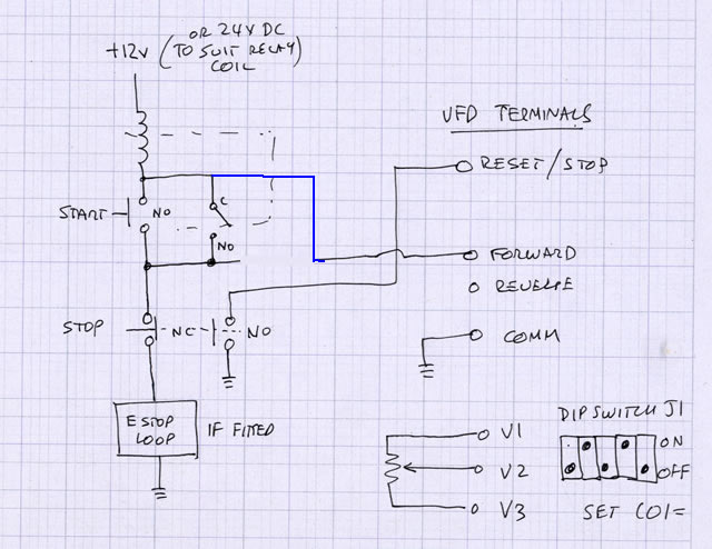
A full discussion on e-stops could be quite a long discussion, the primary objective is to make the system safe. Most often this involves a latching contactor on the mains supply with a chain of interlocked e-stop's and maybe other sensors as well. When tripped it kills ALL the power to the machine, as to whether that's the safest strategy depends a bit on the specifics of the machine, sometimes it's safer to stop the machine in a controlled fashion before killing the power.. Keith_W who sometimes posts here could probably explain the choices better than I can.
Just stopping the vfd is fine for tool changes.
Normally you don't have a contactor between the vfd and the motor. ( I'm a bit unclear from your description as to how it's wired ).
A circuit diagram of what you currently have would be good.
Regards
Ray
EDIT Here's one I prepared earlier... shows a latching relay that locks out the vfd control. ( I realise that your machine will probably be different to this one, and I forget what this one was for, I might have been one of RC's projects from memory)
-
17th October 2012, 07:23 PM #30
GOLD MEMBER
- Join Date
- Aug 2011
- Location
- Melbourne
- Posts
- 2,951
Hi Ray, Originally Posted by RayG
Thanks for the reply. I don't actually have a circuit diagram yet as I'm still developing the control circuitry and switch layout on the new control box. Your diagram and replies from Stuart and others pretty much answer my questions regarding safe control of the VFD.
Cheers,
Simon


Similar Threads
-
Converting 3 phase to 1 phase
By angryranga in forum GENERAL & SMALL MACHINERYReplies: 2Last Post: 3rd May 2012, 10:25 AM -
Star/Delta motor wiring
By .RC. in forum METALWORK FORUMReplies: 33Last Post: 3rd March 2012, 11:01 PM -
Advice re: Converting 3phase to single phase
By Nielsen in forum TABLE SAWS & COMBINATIONSReplies: 15Last Post: 25th June 2009, 05:25 PM -
converting a combo machine to 3 phase
By currawong in forum TABLE SAWS & COMBINATIONSReplies: 14Last Post: 23rd January 2008, 09:08 AM -
Converting 3-phase compressor to single phase
By Big Shed in forum HAND TOOLS - POWEREDReplies: 12Last Post: 20th November 2007, 06:06 AM
Tags for this Thread
$40,
added,
block,
confident,
connected,
connecting,
connection,
connections,
converting,
cover,
delta,
diagram,
existing,
fibreglass,
heatshrink,
insulated,
insulation,
laquer,
motor,
phase,
piece,
pretty,
rated,
rpm,
soldered,
star,
terminal,
windings,
wire,
wires
