

 Thanks:
  Likes:
  Needs Pictures:
  Picture(s) thanks:
Results 1 to 15 of 33
-
10th April 2013, 10:38 PM #1
 SENIOR MEMBER


- Join Date
- Aug 2012
- Location
- Australia
- Posts
- 521
 MD45/HM46/RF45 DRO Install as requested..
A while back Dave J requested (https://www.woodworkforums.com/f65/mo...ml#post1611213) that I post some photos of my DRO install. Despite my best intentions I never got around to posting what I had done. Dave J (and lots of others here) have helped a lot of people (including me) with useful advice and I figure it is the least I can do. I also want to send a big thanks out to Pipeclay who helped me out more than once. A few months back Pipeclay generously made me up a drawbar that has been absolutely flawless.
Disclaimer before I start: I am not a machinist. At the time I installed the DRO I had owned the mill for about 2 months total. I had at played with it on my weekends and few nights after work when I had some spare time. The only training I have is what I read (here among other resources) and watched on Youtube. This is not a professional install.
On to my DRO (thedrostore.com) install:
One thing I noticed in the DRO manual was that the general idea was to move the scale and not the reader head if possible. By moving the scale one avoids constantly dragging and moving the reader cord and thus reducing wear somewhat. In some instances it would have been easier and less time consuming to mount the reader on the moving axis, but it was not advised. So everything you see here is with that in mind.
When I opened the box my impression was that all the parts looked well finished and professional. Aside from the scales, screen and covers there was an assortment of bolts, shims and some aluminum mounting brackets. Despite the best intentions of the supplier, the bolt kit was far from ideal. I guess it is hard for them to cater to every installation. I had to make up quite a few mounting pieces and purchased a few bolts in a variety of sizes.
The first part I worked on was the X axis install. I found that the scale would mount fairly easily to the front of the table. Surprisingly it did not need shimming and was easy enough to get square within spec. The guard however was an entirely different story. It was a total pain to cut down the guard so that it was not interfering with the table locking screws. Because the aluminum that makes up the guard is so thin it is difficult to cut on the milling machine without two vices or a vice and angle plate. It was slow going but I eventually got it cut down. There was also a lip on the top of the guard that needed to be removed, so the guard could "snug" under the table lip to stop fluid leaking down onto the scale. I mounted the guard by milling a spacer with a dovetail to fit the mount.


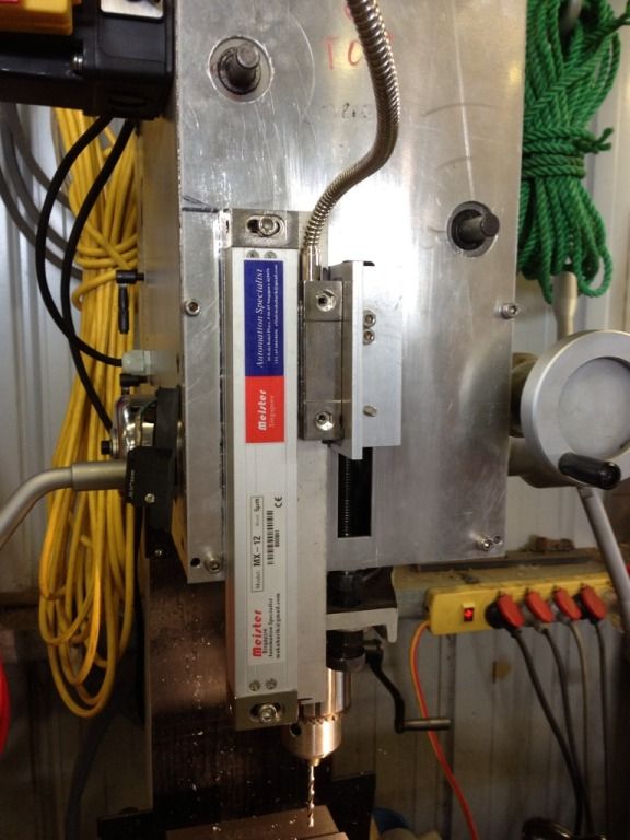
The next cab off the rank was the Y axis install. The X axis was straight forward. The Y however has limited space to mount the scale. Given this and following the suppliers "best practice" I decided to make up a reasonably rigid mount for the scale. This way I could mount the reader to the mill base and the scale to the table. To install the cover I had to mill some spacers and bolt it to the mount I made. Note: Ignore the reading on the DTI. It was as I was testing and had not fully leveled the scale. I spent a considerable amount of time on leveling the scales to well under the manufacturers specs.


The Z axis was reasonably straight forward. I created a spacer and used some of the mounting equipment that came with the DRO. With this one it was not possible (if I recall correctly) to move the glass scale as it would interfere with the mill travel. So the scale had to be the piece moving for this axis.

The DRO screen was mounted next. This was meant to be a quick an easy task but it never seems to be that way! It is a time for decisions, important decisions! The screen is the key part of the DRO. The last thing you want is to mount it in a place where it is either out of sight or gets in the way when using the machine. I am happy with the placement I settled on. It is always visible and does not get in the way. In the photo you can see that I had to machine up a mounting plate to allow for reasonably rigid fixing to the head.

And there it is! DRO install complete and some little clamping fixtures and t-nuts that I made thanks to the DRO!

I also built a couple of things to make using the machine a bit easier. The first was a simple tramming fixture. When tramming I was sick of hitting the head with a rubber mallet only to see it jump worse out of tram. I saw a post online that had a simple fixture to help, so I made one for my mill and I can tell you it makes a world of difference tramming. It turned from a bit of stuffing around to a 20 second job to get it perfect.

I then made some machine guards. These are just the side guards that have a magnet to stick them to the table or vice. I intend on making some small ones to help block chips coming off the table. I also made a plastic (HDPE) rear guard that is the length of the table, but for some reason I did not photograph it! Oh, and the angle plates are my own "low profile" angle plates that are not likely perfectly square ;-) but they do the job better than expected!

Anyway, that is it. Hopefully it helps someone with their DRO install.
-
10th April 2013 10:38 PM # ADSGoogle Adsense Advertisement
- Join Date
- Always
- Location
- Advertising world
- Posts
- Many
-
10th April 2013, 11:21 PM #2Dave J Guest
Wow what a really well put together post with clear picture and description, thanks for the post and the time taken to put it all together.
You got that X axis scale and cover to fit real nice, save loosing Y travel.
Most guys with those style of mills have the Y axis bolted to the base with a set up like your Z attaching it, it looks like you way works just as good.
I hope we get more posts like this and I am sure this post will inspire more members to look at fitting a DRO, or give them ideas if they have one to be fitted.
Dave
-
10th April 2013, 11:28 PM #3Dave J Guest
Just looking over the pictures again, I really like those machine guards and am close to making some myself after I finish the coolant tray.
With the angle blocks all that matters is they work, is you place them in your vice with a piece of round at the back to clamp them, you can face them up true.
Also it looks like a nice pile of aluminium in the corner.
Dave
-
11th April 2013, 12:34 AM #4
SENIOR MEMBER
- Join Date
- Aug 2012
- Location
- Australia
- Posts
- 521
Thanks Dave. The X axis cover certainly took some fiddling to get right. As for the Y axis, I know most bolt it to the base with some sort of "hang over arm" type fixture. It took a lot of standing looking before I started milling. I actually made it twice. The first time I used a piece of aluminum that was a bit thin. I did not want it flapping in the wind with slight vibration so I remade the part in thicker aluminum.
As for the guards, I will post some clear photos of them on the weekend. The back guard hooks into them and works really nicely. I also got some 3mm HDPE to extend the front area of the table under the vice to act as a catch tray. It works remarkably well and keeps the chips on the table especially with a strategically placed machine guard. I was sick of walking them through the house. Finding steel swarf stuck in my heel when I put it on a foot stool in the lounge was the last straw. The significant other was also not overly impressed that the cat was getting around with aluminum stuck to her fur thanks to my "swarf walking" (the cat is not allowed in the garage) .
.
I would have made the smaller machine guards, but I ran out of 25sq aluminum and they have to order it in at the local supplier . Pretty much stops me dead in my tracks every time.
I will be squaring up the "angle iron" angle plates soon. I purchased one of those Glacern FM45 Face Mills. I purchased some good carbide inserts so should be able to square it. I have put it off because I need to re-shim my column first which is never fun..
I have been collecting quite a few thicker bits of aluminum. I recently got some 32 and 50mm thick bits. As well as the usual suspects 25mm thick. My steel collection also growing. The last run I ended up buying some 300x6 which was a pain to cut on my BS-5S bandsaw. The local steel supplier now refers to me as "that bloke that keeps buying stuff".
I have made a bunch of t-nuts out of 25sq steel with different threads; M8, M10 and M12. My latest happenings from the mill are:

Cue the obligatory "chip shot"


-
11th April 2013, 01:13 AM #5Dave J Guest
You have come a long way in a short time

Those slots look spot on, just remember a fly cutter leaves a really nice finish and some people have run just one insert in the face mill to act as a fly cutter, so give it a try when you get a chance.
When I got my DROs I spent 3 weeks installing it on the mill as I made up 10mm thick steel plates for everywhere, then within 12 months the mill was returned and the next one I got had a DRO fitted
I did find the factory fitted scales with 5mm bolts where plenty strong enough, where I used 6mm on everything. I made the brackets that strong so if anything hit them they would not move, but the factory aluminium brackets are doing fine. Also with the 5mm bolts it give you wiggle room instead of having to be exact.
They factory knew this as when they fitted the scale to the back of the table the bolts threads where drilled at 30 odd degrees, luck I moved it.
The lathe still has a piece of 10mm plate on the carriage reader head, LOL
Personally I hate having to over lapping on a cut and my usual milling cutters are up around 18 -20mm to stop it some what, any wider and I use the face mill.
I have also made a lot of T nuts for the mill and shapers and have a few strips in the cupboard for special ones. Like you I made some with different size threads as some jobs you need them.
For the table guards I am thinking of something like shower screen extrusion so I can slide in rubber to hold the perspex, then have it attached to the table and have it hinged.
I am also thinking of a table extension forward under the vise, it will serve no purpose other than to stop chips.
Something like this from CNC zone, but with a flat top on it
Knee Mill Chip Containment
Dave
-
11th April 2013, 09:58 AM #6
Senior Member
- Join Date
- Feb 2011
- Location
- Mornington Peninsula
- Posts
- 183
Very similar to how I have done mine!
Looks great.
A lot of the issue you had I did too, the aluminium splash guards were very tricky to machine, I kept getting aluminium build up on the cutting edges.
I couldn't really use coolant because I used heaps of MDF to try and clamp the things in the vice.
Did you put a scale on the Quill? I made up a new aluminium face for the front of the mill that I milled a 20mm slot in and then machined up a T piece from polyethylene that runs inside the slot. I then used some aluminium right angle with some some PVC. This all clamps together ensuring the quill depth gauge goes up and down smooth and square. I had the reader moving as opposed to the scale for that set up but I have left enough cable that it can easily move without damage to the cable.
Picture tells a 1000 words:
The Z axis I'm yet to do but I think you have given me some ideas.
My X and Y axis are very similar.
I should really take some pictures and start posting.
Cheers
Justin
-
11th April 2013, 01:20 PM #7Dave J Guest
Nice job Justin, you have gone to the extra effort and it will pay off in the future.
On another forum (cnc zone) a member made a new plate like yours and etched it, it looks fantastic.
I too mounted my quill scale with the main body fixed and the reader head moving, I think it's the only way to mount them there.
When machining aluminium in the future try some WD 40 or some kero in a spray bottle, a fine mist shouldn't upset your MDF, or you could wrap a bit of cling wrap around it to protect it.
I wish you had of taken pictures of all this work you have done already, but I would be interested in seeing your design for the rest of the scales as there is always little tips that can be pick up along the way.
I should post up my quill scale as there is a little trick you can do using sail track extrusion, and it makes great little holders for the cable.
Dave
-
11th April 2013, 01:33 PM #8Dave J Guest
Hi Justin,
I think your mill is like mine with a 2hp motor?
After looking at the picture again and seeing that power pack, try to have your mill directly plugged into the wall socket if you can, otherwise you will not get full power to it. If you have to run a extension lead make sure it's a good heavy on like they use on the 15 amp caravan ones or the builders leads. All the accessories are fine but the mill needs all it can get.
I too used to run the mill off the power pack but it kept tripping out the 10 amp pack, so I changed over and there was a difference in power when pushing the mill in steel.
Because of there expense and delicate circuit boards, I run a surge protected power pack for my DRO's, it saves them from power spikes, lightning etc and is a worth while investment. I bought mine from Dick smiths and it is supposed to be for computers, TV's etc with phone and arial plugs in it, but they don't get used in the shed.
Dave.
-
11th April 2013, 02:16 PM #9
Senior Member
- Join Date
- Feb 2011
- Location
- Mornington Peninsula
- Posts
- 183
Dave you pulled me up on the power point a while ago and I have yet to rectify it.
Suffice to say it will be fixed I will put in a dedicated power power point for the lathe and the mill.
Cheers
Justin
-
11th April 2013, 07:28 PM #10Dave J Guest
Sorry, I have forgotten I said something or I wouldn't have repeated myself
I did go to the doctors the other day and said to him I think I have Alzheimer's, he replied "Try to forget about it"
Thought I would throw that one in, LOL
You have been using it the way it is and as you know it will run fine, but it does rob power from the mill.
Dave
-
12th April 2013, 10:02 AM #11
Senior Member
- Join Date
- Feb 2011
- Location
- Mornington Peninsula
- Posts
- 183
Dave don't be sorry, I wasn't the least bit offended! I know it has to be done and I know its less than ideal. Originally Posted by Dave J

Cheers
Justin
-
12th April 2013, 02:18 PM #12
GOLD MEMBER

- Join Date
- Aug 2011
- Location
- Melbourne
- Posts
- 2,951
Hi Variant, Hi guys.
Variant, great post and great detail. I can really relate to your projects and your thought processes as I too are still learning and find that we both have a similar approach to such projects. I'm yet to install a DRO on my mill (or lathe) mainly the cost being prohibitive factor but the more I see such fine installs as yours, the more it tips me over the edge to do the same. I'm also getting quite tired of counting handwheel rotations
I couple of questions for you (or other too if they feel like it) if I may,
If I have a basic DRO on my quill (same as yours and everyone else's) should I still look at getting a 3 axis DRO? Is the scale on the Z axis used in conjunction with the quill DRO so that one can keep track of the overall height from a pre-defined datum?
Actually, the next is a comment and not a question. Nice work in the guards! the idea of a magnetic mounted & removeable guard is an idea I never thought of. I'm also getting in trouble with swarf from time to time eventhough I change shoes, it seems to like my socks!
Dave, I use a powerboard too. Guilty as charged!
Cheers,
Simon
-
12th April 2013, 03:53 PM #13
GOLD MEMBER
- Join Date
- Jun 2007
- Location
- sydney
- Age
- 64
- Posts
- 3,566
I'm also getting in trouble with swarf from time to time eventhough I change shoes, it seems to like my socks!
Just wear thongs.
-
12th April 2013, 04:34 PM #14
GOLD MEMBER
- Join Date
- Aug 2011
- Location
- Melbourne
- Posts
- 2,951
Actually, after wearing big heavy boots at work all day/night, I seem to crave getting around barefoot. There was a time when I would duck into the shed with nothing but bare feet if I was just in-out to get something. Until one day when I stood on a metal self taper. I went in about 1/2 inch into the meat of my foot. While it was painful when it happened, it hurt more coming out than going in!
I still sometimes wear thongs if I'm just dicking around but if I need a little more safety then I opt for the Chinese safety boot and wear socks with my thongs.
Simon
-
13th April 2013, 09:59 AM #15
SENIOR MEMBER
- Join Date
- Aug 2012
- Location
- Australia
- Posts
- 521
Dave J: The table swarf catchers you posted look really nice. The only issue I can see for my use is that they might get in the way a bit. I have my milling machine near a doorway (only place I could fit it in my garage) and I could see myself getting snagged on the corner. Maybe having the ends angled in would do the trick. I have not decided on my design. I was going to start with a piece of 3mm HDPE the and a couple of strategically placed guards. To be honest for my manual machining the strategic guard placement works wonders and never gets in the way of setups etc. The low profile ones will be even better. They are just so useful to stop chips flying everywhere and they give me a nice false sense of safety!
As for the super reinforced DRO guards, you must really love your DRO! I thought about the potential for dropping stuff on the X scale and damaging it, but then though "bugger it". Too much work for the limited amount of time I have to "make stuff". I figure if I kill the scale I can always buy another one..
Jarh73:Nice to see your setup. I really like your quill DRO. I neglected to install a glass scale on my Z. I have one of those cheap vernier type scales on my quill. It came installed on the mill. I should havedone it the same as you have done. What DRO are you running to take two Z scales? Mine (drostore) only has a single input for Z.
simonl:One important thing for anyone looking at DRO is to consider how you want to do your Z. If I had of thought hard about it I would have purchased a DRO that takes two scales on the Z. That way you can have the best of both worlds, in a scale on the Z column/head, and a scale on the quill reading out on the single axis displayed on the DRO screen. That being said, I get by just fine with the setup I currently have. The Z scale just helps set tool position and the quill is just depth of cut if I am not worried about rigidity. I do not find it to be cumbersome, it seems to work nicely. I quite often need to change out tools for a small bit, then go back to my original tool with the correct Z. If I only had Quill DRO I am not sure how I could do this, as I need to move the head up to change the tool.. that said my Quill DRO is rather essential for quick and nasty depth of cut stuff, like in my machine swarf guards where it is aluminum and the loss of some rigidity is not really of any consequence (that I can see).
Final comment for Dave J: Ok, I admit it. I am also using a power board for my mill and DRO... I have a big dream to run a 15amp line to the mill, but as it sits it is just that - a dream..

Similar Threads
-
HM46 Z axis Gib screw issue
By variant22 in forum METALWORK FORUMReplies: 6Last Post: 4th March 2013, 09:09 PM -
More gear head mill problems - SM-MD45
By variant22 in forum METALWORK FORUMReplies: 18Last Post: 15th February 2013, 10:34 AM -
HM46 CNC convserion
By chris... in forum METALWORK FORUMReplies: 4Last Post: 24th October 2010, 12:21 AM -
Another source of RF45 clone Mills
By hux in forum METALWORK FORUMReplies: 5Last Post: 19th May 2007, 04:46 PM
