

 Thanks:
  Likes:
  Needs Pictures:
  Picture(s) thanks:
Results 76 to 90 of 950
-
4th June 2015, 08:16 PM #76
 GOLD MEMBER


- Join Date
- Nov 2008
- Location
- Canterbury UK
- Age
- 67
- Posts
- 3,996

Looks like you are going to have fun sitting there and cutting all the spokes out.
Thank you for the compliment Keith but it is you who is the craftsman along with many others on here. Originally Posted by Keith_1

After the last few days weather we have here Fletty will be glad to get back Originally Posted by Keith_1
-
4th June 2015 08:16 PM # ADSGoogle Adsense Advertisement
- Join Date
- Always
- Location
- Advertising world
- Age
- 2010
- Posts
- Many
-
4th June 2015, 08:59 PM #77
Deceased
- Join Date
- May 2008
- Location
- BELL POST HILL, 3215
- Age
- 87
- Posts
- 2,332
Sizes ??.
Hi All,
Not trying not to be a smarty pants, but instead of mm, wood 'nt be in Imperial.
I realise it maybe easier to do in mm, but I wood have thought that the UK people wood have used Imperial.
Just a thought.Regards,
issatree.
Have Lathe, Wood Travel.
-
4th June 2015, 09:31 PM #78
GOLD MEMBER
- Join Date
- Apr 2013
- Location
- Torquay
- Posts
- 4,422
Derek,
Cutting out the spokes is going to be the easy bit. That is why I made the centre removable hub. I will cut out using the bandsaw and then glue it all back together. The monotonous bit is the filing and sanding of the spokes once glued together. But, the boring bit then becomes one of the more lifelike bits of the build so it is well worth the effort. The counterweights will be interesting. Have figured out an easy (cheat) way of doing them that will also add strength to the wheels. Cut them out first and then do the spokes and then make up a tight fitting counterweight to glue back in position between the outer rim and spokes.
I don't think Fletty will want to come home from the UK mate - it is so cold down here. Didn't even reach double figures Celcius today and pouring rain.
Regards
Keith
-
6th June 2015, 05:11 PM #79
GOLD MEMBER
- Join Date
- Apr 2013
- Location
- Torquay
- Posts
- 4,422
Hi,
Did a bit of work this afternoon on the wheels. I had cutout the wheel spoke templates I did on Thursday and glued them onto my inner blanks with some PVA glue.
Today I started cutting out the spokes on my bandsaw. The only filing I have done so far is to clean up the blade marks near the hub. I then glued the inner to the outer. These will be left at least 24 hours before any filing or sanding takes place.
The wheel with the counterweight was done in a similar fashion except I cut off the counterweight moon shape and then made a tight fitting new counterweight. The counterweight is the same width as the outer rim, so a new one has to be made for each of the driving wheels. Important that it is a tight fit to ensure the spokes are positioned correctly when inners and outers are glued together. 10 more to go. Then filing the spokes straight and then rounding off the spoke edges.
Regards
Keith
spokes1.jpgSpokes2.jpgSpokes3.jpg
-
7th June 2015, 12:01 PM #80
Hotrod
- Join Date
- Jun 2010
- Location
- Leander, TX Central Texas Area
- Age
- 45
- Posts
- 1,061
Great build sequence for the wheels Keith. Creative thinking on parts like these is what makes complicated parts look real.
Bret
-
7th June 2015, 12:31 PM #81
Most Valued Member
- Join Date
- Aug 2010
- Location
- Horsham Victoria
- Posts
- 5,713
Wow thise wheels looking good
Dave TTC
Turning Wood Into Art
-
7th June 2015, 05:22 PM #82
Senior Member
- Join Date
- Nov 2013
- Location
- Sydney
- Posts
- 260
Fantastic work Keith ! I would like to ask you for a bit more info to be included in the WIPs. What method/machinery do you employ to make them ? Do you use machinery to make very small parts ? Originally Posted by Keith_1
Regards,
Gus
-
7th June 2015, 08:29 PM #83
GOLD MEMBER
- Join Date
- Apr 2013
- Location
- Torquay
- Posts
- 4,422
Gus, Originally Posted by xpro
If you like I will add more photos.
I turned the blanks for the wheels between centres on my wood lathe. (I need to get a chuck) Not much room for the chisel next to the tailstock. The wheels are out of 240 X 19 pine. Spent all day on the wheels. I cut out the spokes and half moon counterweights on the bandsaw. Then very lengthy time getting the counterweight to fit in. (make up a new counterweight for each drive wheel as it is thicker than the turned inner hub thickness). The fit needs to be an interference fit so there are no gaps between counterweight and spokes.
Attached is photo of one side of chasis (yet to be assembled) This just shows wheel configuration. The wheels still need the spokes filed and sanded. Work on cutting out the remaining wheels tomorrow.
Photo looks a bit weird because used wide angle to get the lot in - but gives some idea")
Regards
Keith
wheel configuration.jpg
-
9th June 2015, 06:20 PM #84
GOLD MEMBER
- Join Date
- Apr 2013
- Location
- Torquay
- Posts
- 4,422
Hi Guys,
I am really happy. I got the perfect paint match off the paint stirring stick the guys from the Railway Museum gave me. I was told it was "Canadian Red" by guys at the Museum. It was matched to a Dulux colour "Indian Red". It is identical to the sample. Good old Bunnings.
Today I finished fitting, cutting out, minimal sanding and gluing together all the loco wheels. Next step is to file and sand the spokes and give them a rounded edge
Regards
Keith
colour match.jpgAll wheel cut and glued.jpg
-
9th June 2015, 06:48 PM #85
 Life's Good, Enjoy each new day & try to encourage
- Join Date
- Dec 2009
- Location
- Faulconbridge, Lower Blue Mountains
- Age
- 68
- Posts
- 11,185
The wheels look great Keith...you must have been a turner in a former life... Peter
-
9th June 2015, 08:04 PM #86
GOLD MEMBER
- Join Date
- Apr 2013
- Location
- Torquay
- Posts
- 4,422
Thanks Crowie, Originally Posted by crowie
The cutout sections "hide" where all the chisel marks were
Regards
Keith
-
12th June 2015, 06:36 PM #87
GOLD MEMBER
- Join Date
- Apr 2013
- Location
- Torquay
- Posts
- 4,422
Hi All,
10 hours of filing and sanding and I have finally got the spokes and rims somewhere near what I want them to look. All 12 are now done. I can now set up the piston cylinder to get the correct angle to the wheels and make up the cylinder support brackets so they won't foul with the wheels. Then I can assemble the chasis. I need to make up at least 3 wheel axles to ensure each side is aligned and square during assembly and glue setting.
I have placed my VB Gold can in the photo to give some perspective of size. Having the size of the model loco available is beneficial as it shows me whether I am heading down the right track.
Regards
Keith
Wheels filed and sanded.jpg
-
13th June 2015, 12:03 AM #88
Hotrod
- Join Date
- Jun 2010
- Location
- Leander, TX Central Texas Area
- Age
- 45
- Posts
- 1,061
Wheels look great Keith. Thanks for the can reference. It really is larger than it appears. Like your pun there by the way.
P.S. When you are all done you will have to have a pic taken with you holding it. I did this with my Scania and it shocks people to see how big it is.
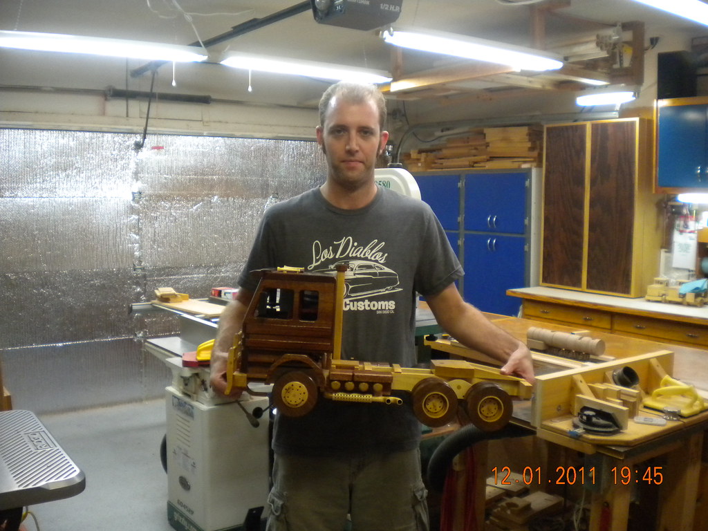 DSCN4527 by bjohnson388, on Flickr
-
13th June 2015, 12:49 AM #89
GOLD MEMBER
- Join Date
- Apr 2013
- Location
- Torquay
- Posts
- 4,422
Thanks Bret, Originally Posted by bj383ss
Will Do,
Truck looks tremendous
Best regards
Keith
-
13th June 2015, 03:38 PM #90
GOLD MEMBER
- Join Date
- Apr 2013
- Location
- Torquay
- Posts
- 4,422
Worked on the cylinder brackets today and worked out the angle of the cylinder to the horizontal point of the chasis - 6 degrees. made up a gauge to ensure I maintained the same angle on both cylinders. Gave a first prime coat. Some sanding required and then another prime coat. I have drilled location holes so the cylinder remains at 6 degrees. I am just using 3mm nails as my locating pins at this stage. Now I have got the angle of cylinders correct - I can start on assembly of the chasis.
Regards
Keith
Cylinder location2.jpgCylinder location1.jpg

 Thanks for the comment about the wheels Derek, but lots of improvement required. Really enjoying it though.
 Reply With Quote


Similar Threads
-
Manual Training for Common Schools - 1910
By pmcgee in forum HAND TOOLS - UNPOWEREDReplies: 4Last Post: 25th January 2014, 07:20 PM -
Window frame timber 1910
By GTHO in forum TIMBERReplies: 7Last Post: 14th September 2009, 09:55 PM -
Toy locomotive
By Andy Mac in forum WOODWORK PICSReplies: 13Last Post: 27th January 2007, 09:48 AM
