

 Thanks:
  Likes:
  Needs Pictures:
  Picture(s) thanks:
Results 1 to 9 of 9
-
1st August 2015, 06:48 PM #1
 SENIOR MEMBER


- Join Date
- Nov 2011
- Location
- Newcastle NSW
- Posts
- 775
 When is a Spindle Moulder a Router
Hey all,
I had two dilemmas, firstly I needed to upgrade my router table, it's done a lot of work, and has seen better days. My second dilemma was that I had purchased a Stenner MAE spindle moulder at the end of 2012: https://www.woodworkforums.com/showth...92#post1580992 and although it only cost me $150 and has the same motor and control box as my Stenner ABM Patternmakers saw https://www.woodworkforums.com/showth...67#post1705667 (so it was worth that for backup parts), I had also at the time managed to get a Wadkin EQ Spindle moulder in a 4 speed (the Stenner is only 2 speed) https://www.woodworkforums.com/showth...53#post1591653 and it is getting very hard to justify 2 spindle moulders in my workshop (this year is about consolidating, although I think I said that last year ).
).
This will be my 3rd router table, so I've got a fair idea of what I want and don't want it to be, my main priorities are:
* Flat table top
* Stable and accurate fence
* Able to handle long/ heavy stock
* Able to perform accurate and repeatable cuts
In the end the answer for me was obvious and solved 2 dilemmas at once. The perfect router table for me, is a spindle moulder with a router fitted.
I debated if it was the right thing to post this or not, my concern being that I may encourage someone to go out and grab a perfectly functioning and worth restoring spindle moulder and scrap it to make a router table, but I have seen enough spindle moulders that have been run into the ground, and end up being scrapped, to say if you consider this approach, please make sure you choose your candidate appropriately.
Now for me, I eventually see a time when 2 spindle moulders (one for tenoning and one for profiling) will occur and also the Stenner MAE in my opinion deserves to be kept complete, so I have removed the spindle and motor, to make room for the router, but I will be making a area inside the cabinet to store this equipment so nothing gets lost.
This isn't going to be a start to finish post, I need the router table soon for a project, so I am going to focus on getting it to a working state first, then I will likely tweak things as I go.
I started, as with most older machines, removing some surface rust. The process I prefer for speed, is an angle grinder with the copper wire (well copper appearance) wheels. The key with this is safety, these wire wheels can do some serious damage to skin if they kick into your stomach, so you have to respect the tool, I find the important thing is to focus on how it will grab at the edges, and orientate the grinder so it wants to climb on the table not jump off the edge:
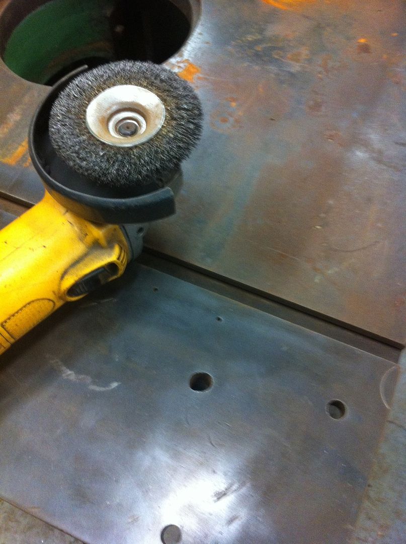
By the way, those marks on the table are existing (some idiot has touched this top in a few places with the wrong tool, but the work area is good). I then followed this up with a green scourer and WD40 for lubricant, to get this (it's not shinny, remember I am going for get it operational, not make it pretty)
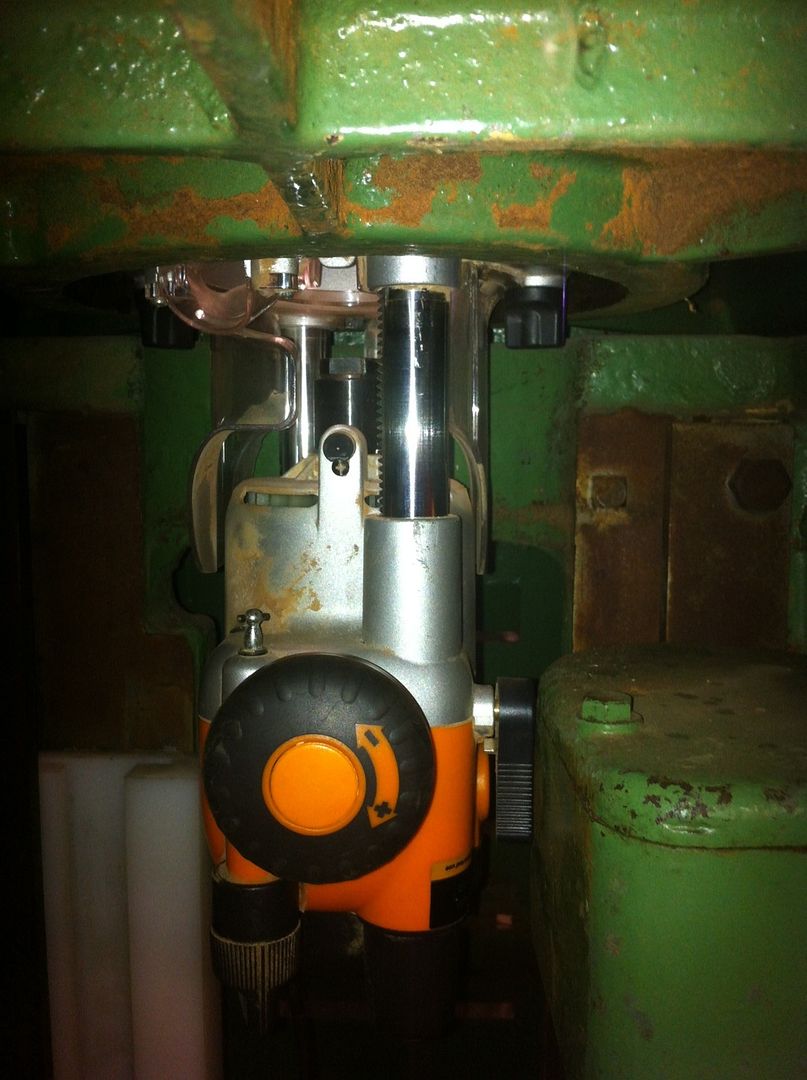
I had visions of using the existing components for router lift, and eventually I will do that, but to get it up and running, I am using my Triton router, so I have lift adjustment built in, and it has the above table setup, so KISS is my approach, and I just need a plate to mount the router to.
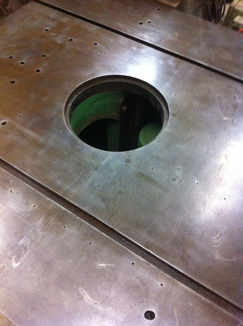
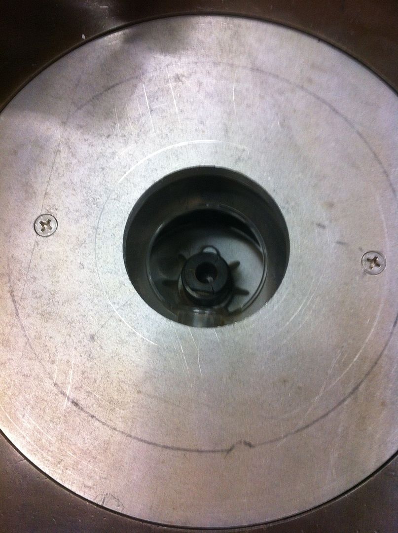
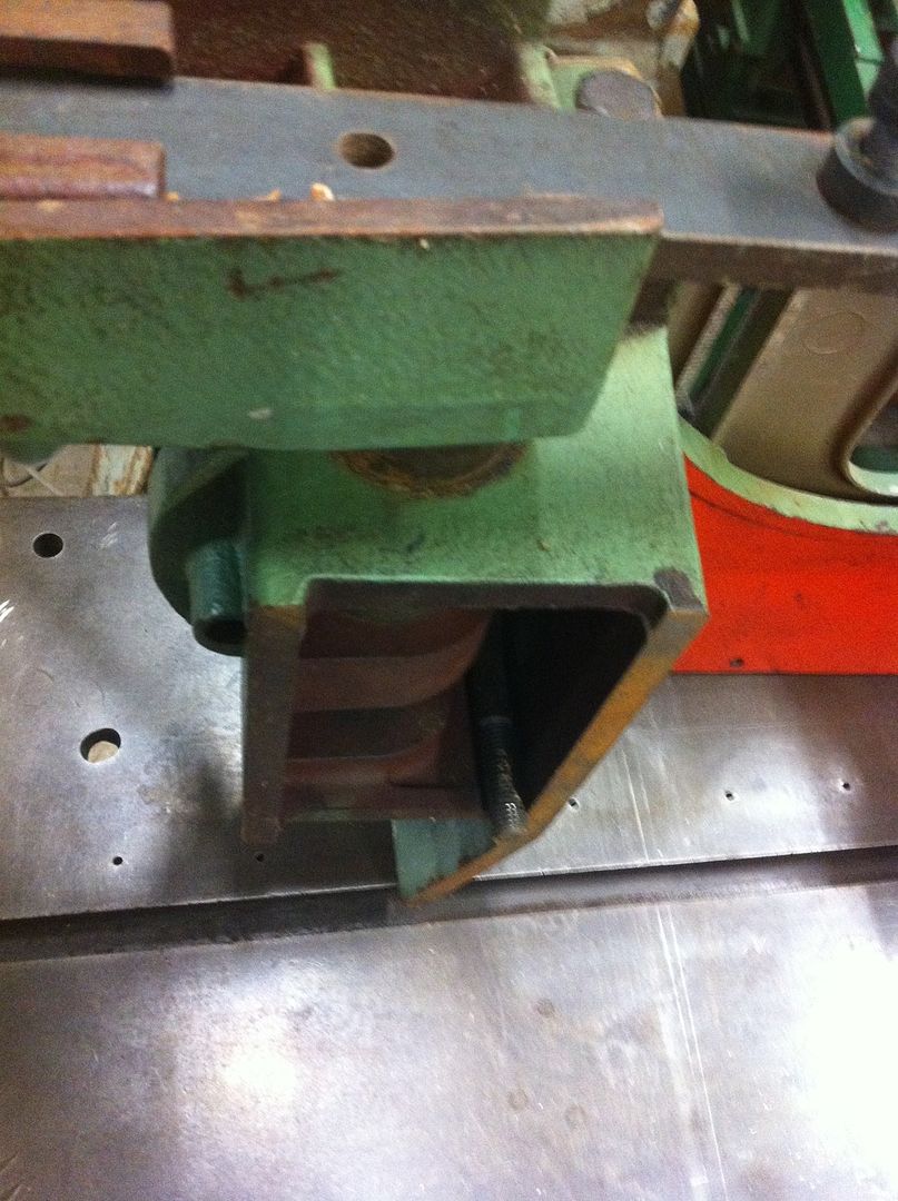
I had a piece of 10mm aluminium plate laying around (doesn't everyone , if not, a scrap metal yard is probably a good spot to look). Spindle moulders generally have a large hole in the table top and 2 rings, so I am removing the rings which gives me just over a 240mm hole with a recessed lip of about 14mm for the aluminium plate to go in.
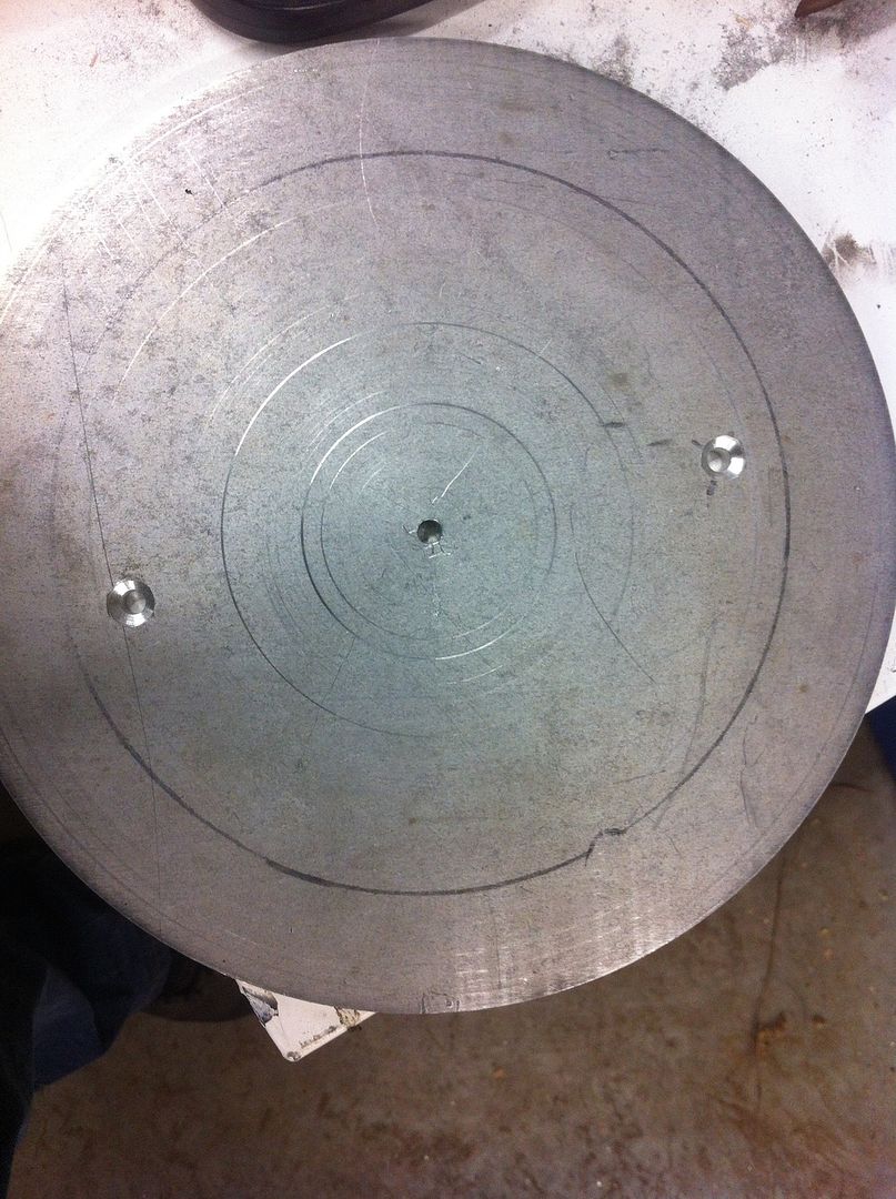
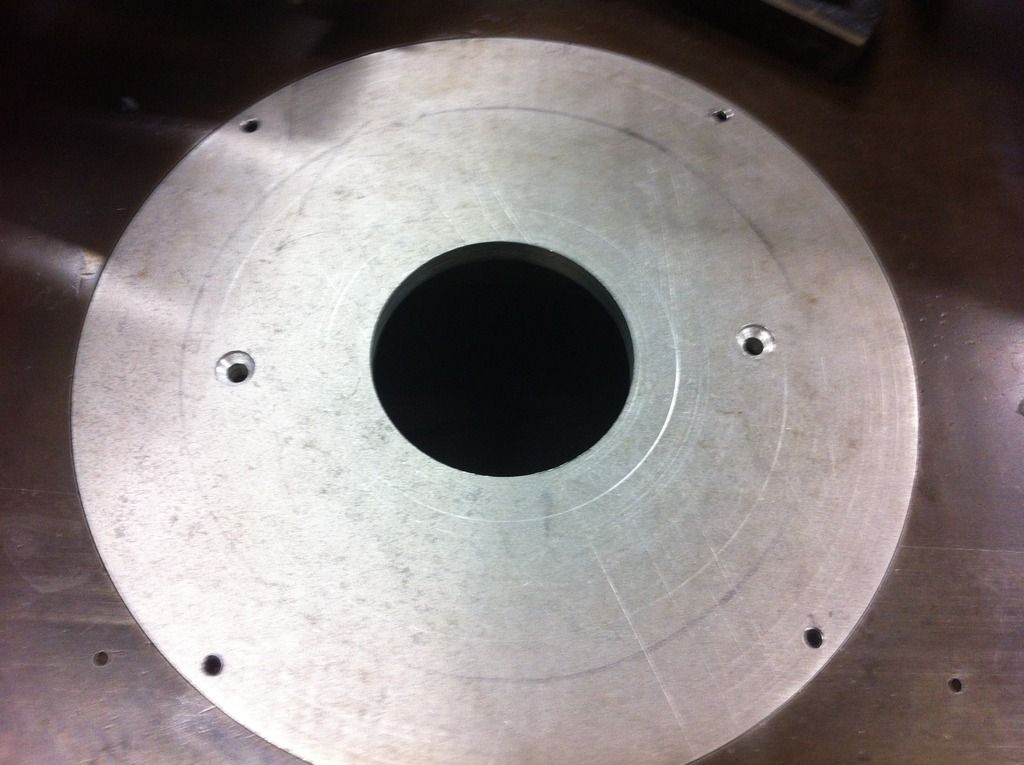
Here was todays progress. I took the aluminium plate, and marked and drilled holes for mounting the router. I then bolted the router to the plate, and inserted a "V" bit in the router, lowered it onto the plate and turned it by hand to mark the centre. I wanted to have the router centred in the plate. Using this centre mark, I then drew a circle the size of the opening in the spindle moulder.
With my scroll saw https://www.woodworkforums.com/showth...72#post1587472 and an appropriate blade, I cut it out close to the line.
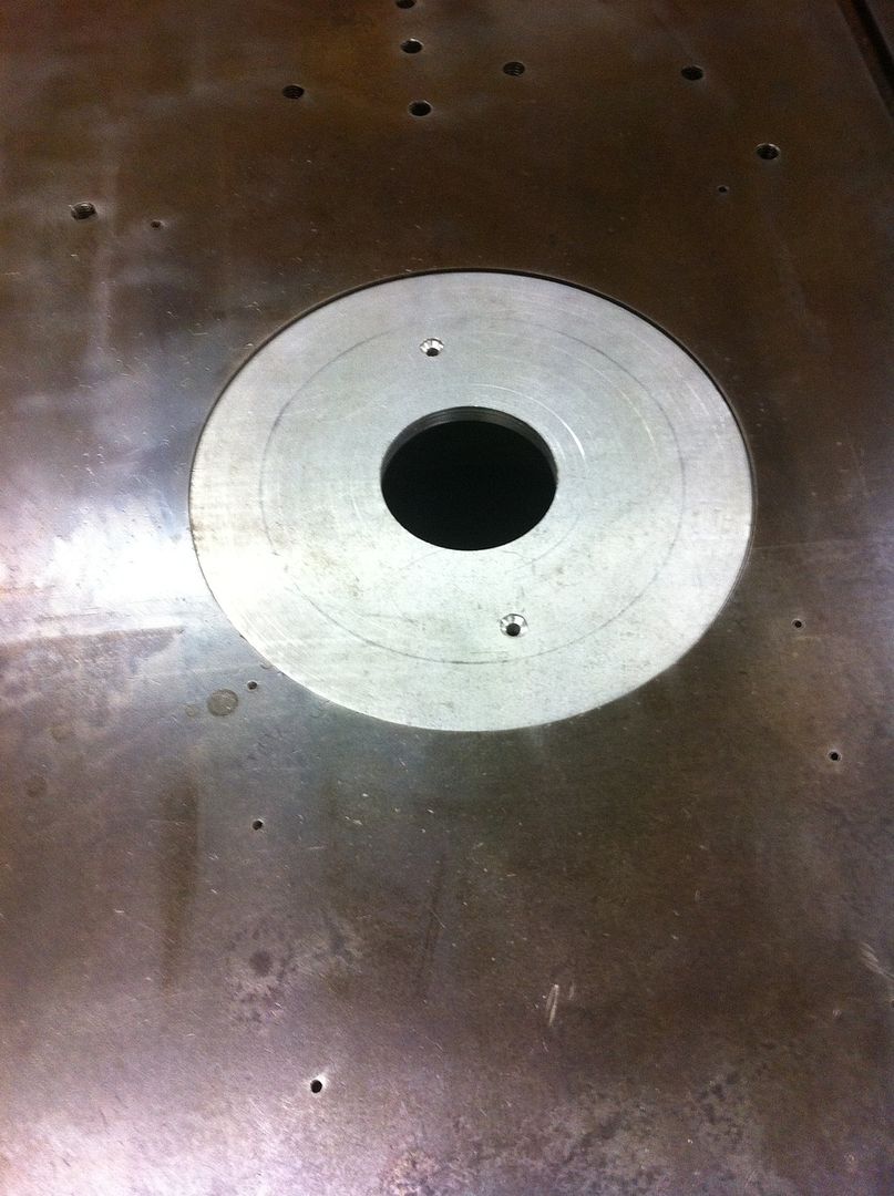
From this point, I had considered making a template and routing to the final finish (aluminium can be cut using a router bit, with care and shallow cuts), but I was pretty close anyway, so I decided to just drill a hole in the centre of the plate, put a bolt through it, and mount it and a file on the edge of my work table. In no time I had a circle that fit the hole, and finished it with some sandpaper soaked in WD40 (I wanted to make sure I didn't make any aluminium dust in the air). The router would have been cooler, but with what I had to take off, this was the quicker way.
From here I needed to open up a bigger hole in the middle, so I can change router bits with it in the table. Later I will make a template and router a lip 3mm deep and make some inserts out of some 3mm aluminium plate (for different size openings). For this, I went to my Waldown 3M drill press (a nice sturdy drill press for a belt drive), I was going to need it. Using a 76mm hole cutter, I gradually cut a hole through the 10mm, the key with this was good clamping, lubrication, taking it slow, and clearing out the hole, and checking for any heat.
Tomorrow, I will need to drill and tap 4 holes on the outer edge, to put some grub screws in (this will enable me to lift the plate up to the height of the table, and level).
Things to do:
I am going to flip the orientation of how the table is usually used by 90 degrees. These spindle moulders usually have 2 groves which run front to back that the split fences slide in. I want a mitre slot for my router table, so by using the table from the side, I will have a perfect mitre slot.
The fence;
It's pretty hard to go past a good spindle moulder fence for a router table
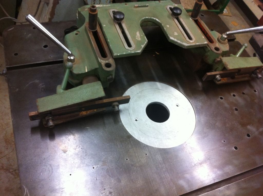
The fence this spindle moulder came with, is not original to the machine, it is off a SCM spindle moulder. There are some things I will need to do, to make this fence work for me though. Firstly I need to mount it 90 degrees to how it should be (as I've said above). To do this, and not modify the Stenner in any way, I am going to use some holes that someone has already drilled into the top (I'm not happy someone drilled so many holes, but at least it means it wasn't me).
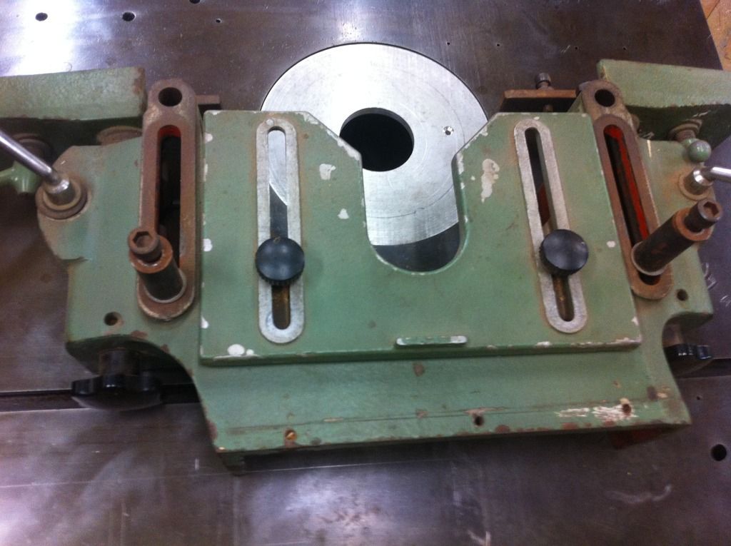
This fence is a split fence arrangement, so each fence can be micro adjusted independently. My aim will be to mount this fence with the ability to micro adjust the entire fence, but more on that later.
Cheers,
Camo
-
1st August 2015 06:48 PM # ADSGoogle Adsense Advertisement
- Join Date
- Always
- Location
- Advertising world
- Posts
- Many
-
1st August 2015, 10:31 PM #2
Taking a break

- Join Date
- Aug 2008
- Location
- Melbourne
- Age
- 34
- Posts
- 6,127
Now THAT'S a router table
-
2nd August 2015, 04:41 PM #3
SENIOR MEMBER
- Join Date
- Nov 2011
- Location
- Newcastle NSW
- Posts
- 775
As you can probably tell, I don't like to do things light Originally Posted by elanjacobs

 . It does mean the Stenner has a rightful place in the workshop now, and it ticks all the boxes for me, with what I want in a router table. The only box it doesn't tick is portability
 , but the old table didn't do that anyway. My first router table was a Triton, it's biggest limitation was not being all that flat, but it has always been my portable table, and I'm used to working with it's limitations, so it suits me for the few times, I find the need to take a router table mobile.
Today was a bit of a slow day for progress (mainly as it is Sunday and I need some bits and pieces to proceed, from some places that are not open), so I decided to drill and tap the holes for the grub screws, to level the router plate. I went with some 6mm x 12mm long grub screws, mainly as this was the ones that I had, and had a suitable drill bit and tap for. Here is the finished product:
There is nothing too exciting about drilling and tapping 4 holes, but it was nice to get this plate level with the table top (basically if I wanted to, I could now start routing). I'm still thinking about the best way to mount the fence and aim for micro adjust on the whole fence, have a few ideas, but not settled yet (I may end up mocking something up first, to see how it works).
Edit: Just looked at the photo, and I really need to remember to hold still when taking the shot (sorry)
Cheers,
Camo
-
2nd August 2015, 06:09 PM #4
Woodworking mechanic
- Join Date
- Jan 2014
- Location
- Sydney Upper North Shore
- Posts
- 4,470
Triton screwed to insert
Will the two screws be strong enough to support the router? My Triton is a heavy beast. Both my plates use four.
Just asking
-
2nd August 2015, 07:11 PM #5
SENIOR MEMBER
- Join Date
- Nov 2011
- Location
- Newcastle NSW
- Posts
- 775
Yeh, it's a valid question, and something I thought about for a bit Originally Posted by Lappa
. The mounting points I am using, are the ones that usually have the spring loaded cup head bolts, not the 4 screws that usually hold the plastic base plate in place (although your router may be different to mine). Did they move away from using the 2 bolt quick release mounting system with later Tritons?
I was thinking 4 holding points was better than 2 initially, but given the router was mounted in my Triton table using these cup bolts for years (I have just replaced the cup bolts for countersunk screw bolts), and the fact that with it being a through bolt, rather than screwing into threads on the aluminum router base, I decided, rightly or wrongly, this was the stronger mounting system (my theory being it's harder to pull two 6mm countersunk bolts through the 10mm aluminum plate, than for 4 screws to strip on the aluminum router body).
Reality is, they would probably both work, but like I said, this is how it has been mounted before for a long time, so I've gone with it.
Cheers,
Camo
-
2nd August 2015, 07:18 PM #6
Hammer Head
- Join Date
- Jan 2005
- Location
- Sydney
- Posts
- 1,205
Nice thinking out side of the box with that one I like it a lot


-
2nd August 2015, 07:47 PM #7
Woodworking mechanic
- Join Date
- Jan 2014
- Location
- Sydney Upper North Shore
- Posts
- 4,470
No-they still have the two spring loaded quick release system for mounting to the steel base plate and fence assembly. My Kreg plates use the four screw holds that hold the round nylon base plate. Originally Posted by camoz
Nice adaption BTW.
-
19th August 2015, 04:30 PM #8
SENIOR MEMBER
- Join Date
- Nov 2011
- Location
- Newcastle NSW
- Posts
- 775
Hey all,
Well been a bit of a break between working on this, but my next step was to make sure that I could use the mitre slot (something I do like to have in a router table).
Given the machine is old English, and never intended to have a mitre guage used in this slot (they were to hold the independent fences), a standard mitre bar is not going to fit.
I've been down this road before, so asking someone to have a bar milled, although it sounds relatively simple from a woodworkers point of view, is actually apparently a bit of a fiddly job, and with setup time, becomes not really cost effective and most places in my area just aren't interested in small jobs. The metal itself though only cost a few $ for what I needed.
So I decided to see if I could tackle this problem myself without the fancy equipment, worst case I was out a about $2 in steel. All competent metal workers and machinists please look away now. I basically had a dovetail mitre slot for the bottom 5mm and then a standard square edge 5/8" slot at the top. I could have just used some square bar (16mm, couldn't seem to find 5/8" for sale in my area, 5/8" is 15.875mm so not a lot to take off), but I wanted the mitre gauge to be captured, it was also a test run for my Stenner Table saw https://www.woodworkforums.com/showth...67#post1705667 which has a much larger dovetail slot and I will be using the same technique in the other slot to secure the router fence later.
I considered just trying to do this freehand with the grinder, but I would have never been able to get a close enough finish that way, so it called for something out of the box.
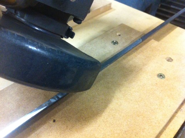
Before I go any further, let me say, you need to consider your safety before trying anything similar to what I did, those who have used an angle grinder know they can be very dangerous (grabbing and jumping back, discs breaking, pieces of metal being thrown etc etc). This is the Frankenstein construction I came up with. I call it Frankenstein because it is made up of bits and pieces that usually end up being given to you when you buy an old machine, they usually have nothing to do with the machine, so most things can be thrown or given away, but some things, I put in a big box of parts should I find a use for them, commonly known as a rat hole.
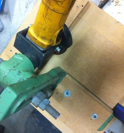
In the image, you can see I have an MDF base, and then two pieces which I cut at the desired angle (for the dovetail) on the table saw. These two pieces are used to sandwich the flat bar and hold it at the desired angle.
The rig I constructed mostly consisted of cast iron, as this created a heavy and sturdy platform, obviously there are many designs I could have gone for, even wooden constructions, but I basically went through my rat hole and thought that will work. The only real building I had to do was construct the bracket to hold the grinder by drilling and welding some pieces of flat bar to bolt through the area that the handle usually screws into. At first I thought I could use this as the pivot point, but the handles screw in so they are not quite perpendicular to the grinder). Again I think all of this could have been built using timber if needed, as long as it was made sturdy.
The key is to have a stable platform, and something that enables you to adjust height, and then also tilt the grinder to change the height of the cutting disc. I extended the base for extra support, and the guard was turned to protect me should the disc break (although it was a grinding, not cutting disc, and I was taking very light passes).
I hold this, with one hand holding the cast extension down to the table, and the other hand holding the grinder and I standing to the left of the grinder (I'm left handed so that felt most comfortable for me). Cuts were made by pushing the assembly along the MDF base in passes then move it so the centre of the disc is over a slightly different area of the piece and taking another pass.
With all things used for the first time, I start out very cautiously, so I had the power running through a foot peddle (so if I removed my foot, power was disconnected), but I also had my hand on the grinder on off switch. As it was, everything felt really secure.
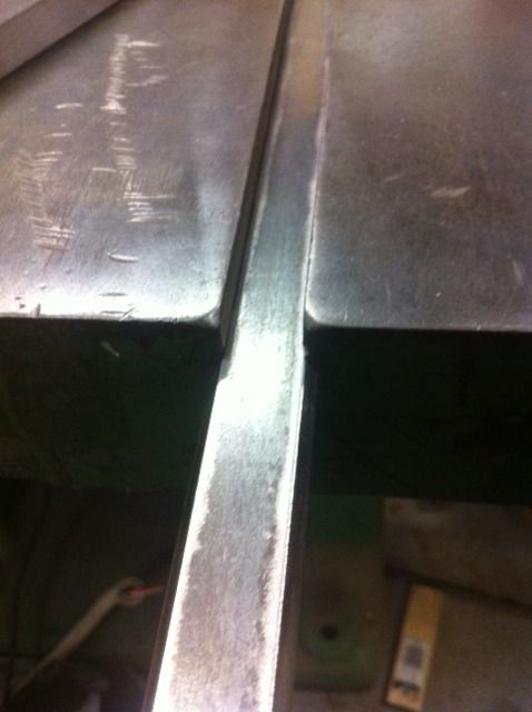
I would then move the bar down to do more of the bar. Once I am close, I dropped the grinder wheel slightly, tightened everything back up, and took one final pass along everything (this was to take out the fact that some of the disc may have warn from the start of the bar to the end). Once one side was done, I flipped the bar around and cut that side down in small passes, checking for fit as I went. Once I was close, I moved to a metal file with the flat bar sandwiched in the MDF and took full length stokes until the bar moved smoothly but with no play in the slot.
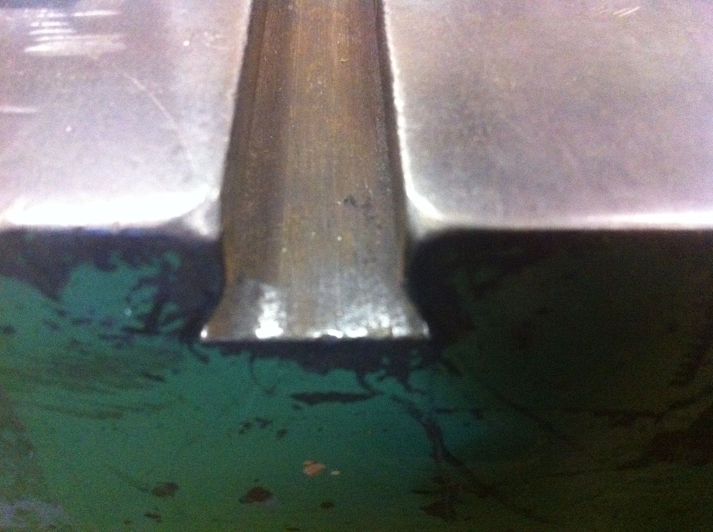
This is the final result
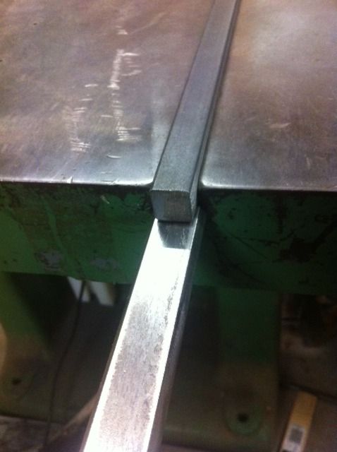
I now need to machine the square bar to go on top (it currently sits proud of the top)
Then I will drill and tap from below to join these pieces using counter sunk machine screws. Finally I will drill and tap the desired holes to take the mitre gauge.
Overall this went much better than expected, to the point that I could have achieved a near finished job without the file, if I had built the jig to handle a micro adjust for the disc height (perhaps something for the future). Another adjustment I would make would be a micro adjust to move the jig from left to right or the workpiece, and set it up to ride in a slot or against a fence, this would have made things quicker as I had to check I had not missed a section by doing a final zig zag down the workpiece (as it obviously only cuts with the very tip of the circle). All these are just extra unnecessary things though.
Regarding accuracy, using a set of callipers I get an even reading, and pushing the bar into the slot, there does not seem to be any points that are loose, so I am very happy with the results. I found the key to accuracy was applying pressure to the base and avoiding pushing down hard on the grinder, although it wouldn't flex much it was the difference between a check pass without cutting, and one with a few sparks.
I will definitely be reusing this jig again for the Stenner Mitre bar. This is a picture with my finished piece sitting in the mitre slot on the Stenner Table saw.....I'm going to need a bigger flat bar
Cheers,
Camo
-
21st August 2015, 11:06 PM #9
SENIOR MEMBER
- Join Date
- Nov 2011
- Location
- Newcastle NSW
- Posts
- 775
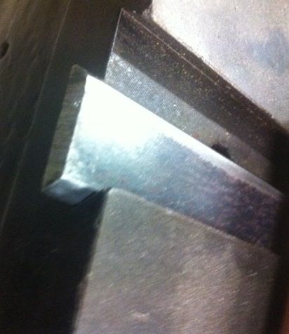
Today I did a bit of final fitting of the dovetail section:
Used the wire wheel on the bench grinder to remove any burs etc. given the technique used, I was very happy with the fit, no play side to side (sorry for the poor video footage, the shaking was me trying to wobble the bar to test for side play, not it getting jammed). I might end up giving it another few strokes with the file yet, but want to attach the rectangle bar and mitre first to see how smooth things slide fully assembled.
Cheers,
Camo


 Reply With Quote


Similar Threads
-
Hammer C3 31 Spindle Moulder / Router bit use
By delbs in forum TABLE SAWS & COMBINATIONSReplies: 3Last Post: 19th June 2014, 06:44 PM -
Router vs spindle moulder
By cava in forum JOINTERS, MOULDERS, THICKNESSERS, ETCReplies: 2Last Post: 8th November 2013, 09:36 PM -
spindle moulder or router table?
By dean11 in forum FURNITURE, JOINERY, CABINETMAKING - formerly BIG STUFFReplies: 11Last Post: 10th July 2012, 04:42 PM -
Router bits in Spindle Moulder
By West OZ Mark in forum JOINTERS, MOULDERS, THICKNESSERS, ETCReplies: 6Last Post: 23rd December 2006, 05:33 PM
