

 Thanks: 0
 Likes: 0
 Needs Pictures: 0
 Picture(s) thanks: 0
Results 1 to 15 of 21
Thread: Building 3 PD Racers at Duckflat
-
30th November 2006, 10:50 PM #1
 Happily receives emails.


- Join Date
- Jul 2005
- Location
- 'Delaide, Australia
- Age
- 65
- Posts
- 8,138
 Building 3 PD Racers at Duckflat
Well, I've just had a big day up at Duck Flat Wooden Boats doing some work on the 3 PDRacers they are building for the nationals at Goolwa in March.
I'm not the only person working on them. Robin Badenoch has been in and more or less finished the masts and is on his way with the foils (centreboards and rudders). He had also made a good start with precoating the plywood sheets with epoxy.
Duckflat staff are also helping when they can steal the occasional moment from the rough and tumble of commercial work.
Just to rewind a little - sorry about the duplication of the mast pics but I just want to get everything in the one thread.
The experimental area in the masts is that they are quite thin walled compared to conventional hollow timber masts. Generally it is recommended that the wall of a timber mast not be less than 20% of its overall thickness - though "with care" it is supposed to be OK to go down to 15%.
My feeling is that to go down less than this in the "good old days" would have been to put the gluelines under too much stress - but glues have improved enormously in the last 30 years. So we went quite a bit smaller to see what would happen with our Mk1 masts. They worked OK but were a little bit too bendy. So we increased the outside dimensions a tad to increase stiffness but retained the same wall thickness.
So those are our Mk2 Masts which are the ones in the plans.
So to the photos below
1/ It can be a bit tricky to make up a hollow mast. In the Oz PDR case it is a two stage process. The masts are made up of four pieces of timber hte length of the mast to produce a box section. So there are two narrow pieces of timber ( narrow staves) and two wide ones (wide staves to produce a box section that is tapered.
The first stage is to make up a "ladder frame" from the two narrow staves with blocking between. The first two photos are actually from Rob Thomson's (Dopey Driver's) PDR.
There are a number of blocks between the narrow staves to space them the right distance. At the base of the mast is a long block that takes the loads right where the mast passes through the deck - the point of maximum load.
2/ After the ladder frame is made up the wide staves are simply glued to the faces of the ladder to make it a long box. We avoid needing lots of clamps by using brown packaging tape to clamp things up. Starting at one end we clamp the assembly together until the glue just starts to ooze out the joins. Then we wrapped brown packaging tape right next to the clamp - which meant that the clamp can be moved about a foot up the mast and the process repeated.
And so on until the whole mast is taped up.
3/ The tape is removed and the mast is cleaned up by sanding off glue ooze and planing or routing the excess width of the wide stave down so they are flush with the faces of the ladder frame.
4/ The corners are routed to a radius equalling the thickness of the staves - any larger radius and the glue joins will start to be cut away.
One of the interesting thing about square masts is that they can be made a lot lighter than birdsmouth masts. Purely because the square section is much stiffer for the same weight.
The booms are solid - it is too much trouble to make them hollow and they don't weigh much anyhow.
5/ This is a pic of me upsetting people. The onlookers weren't as confident as I was - but I already had seen what our Mk1 masts could do.
These masts are designed to bend - a lot!!!
That's how we can manage to carry sails about 30% bigger than everyone else. The masts bend and flatten out the sail which is cut to match the bend of the masts. It is the same system as hot racing boats but here it is very, very cheap compared to their expensive carbon fibre or exotic varieties of aluminium alloy.
Remember our original two PDRs cost us $300 each with some scrounging of materials. A commercial aluminium mast for a PDR would be around the $700 to $800 mark just by itself - or a carbon one between $1000 and $1500. Things that racing sailors take for granted.
Much rather have two PDRs on the water for the same money as a commercial mast or one PDR if you have to buy all the bits.
Michael
http://www.pdracer.info
-
30th November 2006 10:50 PM # ADSGoogle Adsense Advertisement
- Join Date
- Always
- Location
- Advertising world
- Age
- 2010
- Posts
- Many
-
30th November 2006, 11:37 PM #2
Happily receives emails.
- Join Date
- Jul 2005
- Location
- 'Delaide, Australia
- Age
- 65
- Posts
- 8,138
One of the challenges of doing three boats at once is to try and work out ways of saving time - sort of a limited mass production scenario.
One of the labour intensive areas are the foils - the rudder and centreboard blade.
They are made in one continuous length including the shaping of the airfoil section to a high level of accuracy. This is critical to boat performance and we supply template shapes with the plan.
There is nothing particularly difficult about the process - it is just labour with a bit of care chucked in. )
)
The way we went about speeding up the process was to use a router and a jig derived from the original templates. In general it is probably not worth the labour to make a jig for a single boat. But for a series production like this it makes a lot of sense. Also Ducks will be using the template should anyone want a glued up blank (the board laminated up that the foils are shaped from) with the grooves cut in already. Would save most people quite a bit of time.
Anyway ... to the photos Batman ...
1/ This is the drawing from the plan. The foil shape is a little unusual in that the section between the two lots of hatched lines is perfectly flat. This makes the foil a lot simpler and a lot faster to shape. The actual curves used for the airfoil shape were developed by Melbourne aerodynamicist Neill Pollock a decade ago after extensive computer optimisation.
For those in the know - we didn't go for fully shaped foils with a conventional wing sections as they would have to be too thick - the normal thickness is around 10% meaning that the foils would end up being about 30mm thick rather than the 22mm here. More weight, More timber, More money and More Labour.
2/ This is the glued up blank. Here it is about 25mm thick about to be thicknessed down to the 22mm (exact) that is the starting point for using either the router method or the handshape method using the template shape in the plan.
You add a gluing powder to the mixed epoxy that increases the strength of the join. It also knocks the h3ll out of the thicknesser or plane blades if you do it manually. So I generally use the powder that is added to the epoxy for an easily sanded bog mix for filling hollows in hulls etc. The plane or thicknesser blades will hardly notice it.
3/ The blank is cut to the finished outline then the router guide is used to run grooves across the surface. You can see how they terminate leaving a flat area in the middle which won't be touched. The leading and trailing edges are different.
As it was the first time we used the jig we got a bit excited and did far too many grooves. We could have done about half the ones shown.
4/ With the shaping of all foils it is a gradual move from tools that remove huge amounts of material - powerplanes, through normal planes then finally sandpaper round a long block.
The PDR foils are pretty small so a few swipes of the powerplane (set fine) result in us having to put it back on the shelf as a bit drastic.
So used a long bedded plane to work along and bring the surface down to match the bottoms of the grooves. OR RATHER - ALMOST to the bottoms of the grooves. If the grooves are remove then your one and only reference point is gone.
So right at the point of this photo the plane has been put aside and a long wooden block with some 100 grit alumina paper wrapped around is being used. The block should be the same length as the long axis of the sandpaper.
The long axis of the block should remain aligned with the long axis of the blank at all times but is moved at a 45deg angle to its long axis.
5/ Rob Badenock here finishing off the foils - working carefully. The nice thing about the flat section in the middle of the foil is it is very happy just sitting flat on the workbench.
A great deal of care must be taken to get rid of any bumps - particularly from the leading edge which must be finished as a nice radius. Generally I spend about 60% of my time on the leading edge - which represents only about 30% of the area.
The back edge is finished with a small flat surface about 4mm wide. This is wide enough so that it is quite strong in conjunction with fibreglass.
Now the shape at the tip looks pretty terrible in this shot - but that is because the bottom of the blank is still jagged - the staves haven't been trimmed to their final lengths.
More to come - I have more pics and info from laminating the chine logs and cutting the side panels and deck panels out today.
I'll be up there again next week to get on with it. I hope to get the boats to 3D stage next week before I head up to Sydney for Xmas. That means they can be registered.
This will double the current number of registered Australian PDRs to 6 and bring the worldwide number of the class in general to 123 - unless of course the number ends up even bigger!!! (almost 400 boats built end 2009)
MIK
http://www.pdracer.info
Michael Storer Wooden Boats blog
Last edited by Boatmik; 13th November 2009 at 01:22 PM.
-
13th December 2006, 10:44 PM #3
Happily receives emails.
- Join Date
- Jul 2005
- Location
- 'Delaide, Australia
- Age
- 65
- Posts
- 8,138
Laminating chine logs
Hi All,
One of the things that people are often scared about is laminating timbers.
The chine logs of the PDR hull that holds the bottom to the sides are made up from two layers of timber - the bend is probably a bit tight for most timbers to make the curve of the edge of the side panel which is where the chinelogs end up being glued.
The main two things I always need to remind myself to follow are:
a/ Always put down plastic or brown plastic packaging on everything that you don't want the epoxy to stick to.
b/ Always do a dry run if you are unsure whether you have enough clamps.
So to the illustrations
1/ This is one of the many detailed drawings from the plans. The text in that diagram is pretty well self explanatory. I put plastic sheet down on the worksurface and also put brown packaging tape between the different chinelogs - I was gluing six at the same time on the same setup though this illustration only shows two.
If gluing two chinelogs only the setup gluing and clamping will only take about 10 minutes in total. Draw the line by placing the ply side panel on the table and marking the curve the chinelogs will eventually be glued to.
Whack in a half dozen gyprock/drywall/plasterboard screws making sure the shaft exposed is wider than the laminations so the heads won't start pushing things out of alignment.
It is quite rare in laminating to use only two layers of wood. But in this case the purpose was to simply give a bit of prebend to prevent them from breaking when they were adjusted to the final curve when glued in position (see final pic)
2/ Here you can see the curve. The chinelogs look pretty tragic here - with the leftover bits of plastic tape and excess epoxy on the surfaces. But a quick blast over with a belt sander or other sander and they come up a treat. The timber being used here is some clear NZ white pine that the ducks have been using for building. The occasional bit goes somewhat crazy (does the crapiata trick) but most behaves quite nicely and is a low enough density that the boats will come out somewhere near the design weight of 55lbs before painting and the other bits happen.
3/ A close up of the end of the chinelog - just so you get a really clear idea.
The next couple of pics are stolen from the following weeks work where I spent three days at Duckflat overseeing the assembly of the three hulls. The pics are here so you can see where the chinelogs end up and how they are attached.
4/ Here we have Geraldine, a work experience student from the local highschool, screwing the chinelog into place using the gyprock/drywall screws. She was actually really quite talented. Her woodwork and finishing skills were better than mine - very neat joinery and a good understanding of the larger saws - but I could still beat her as far as assembly went! Thankgoodness for that!
5/ This is a slightly fuzzy pic of the other side. After the glue had set up it was all sanded clean and a radius routed on the inside corner of the chine log which finishes up inside the boat.
You can see how nicely Geraldine has aligned the edge of the chinelog with the edge of the ply.
_____________________________
Best wishes
Michael
www.pdracer.info
-
15th December 2006, 12:30 PM #4
Happily receives emails.
- Join Date
- Jul 2005
- Location
- 'Delaide, Australia
- Age
- 65
- Posts
- 8,138
Hi All,
by the way did you notice the kinks in the chinelogs?
Particularly in the photos in the post immediately above showing them sitting on the table.
Those kinks are supposed to be there - the bottom of the boat is not a perfectly fair curve but has a slightly flatter section in the middle.

The originator of the class "Shorty" Routh www.pdracer.com found that without the flat the boat tended to hobby horse a bit.
My gut instinct tells me that maybe it doesn't make as much difference as he thinks but it's there in the rules so has to be a feature of all the boats.
It does stop them from rocking all over the place on the beach though!
The class rules allow a tolerance of half an inch in building - plus or minus from any measured point. I used that when drafting up the OZ PDR hull to flatten out the rocker so you have to make the OZ PDR bottom shape to that in the OZ PDR plan. I've left enough room for little mistakes - maybe up to 1/4" but bigger ones may mean the boat doesn't fit the rules.
The advantage is that the OZ PDR has a flatter rocker for a higher top speed and I've manipulated the shape a bit since the Mk1 version of our first two boats to try and keep the nose a bit lower when planing.
The other obvious difference is that we have used a bit of sheer curve along the deck edge of the side panel. This cuts weight but gives the boat a bit of freeboard where it needs it (at the front) but keeps it low where it isn't needed (the middle of the boat to some extent and in the stern quite a bit.
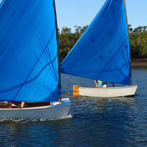
Here is Shorty's flat sheer boat

And here are ours with the curved sheerline/deckedge.
MIK
-
27th December 2006, 12:34 PM #5
Happily receives emails.
- Join Date
- Jul 2005
- Location
- 'Delaide, Australia
- Age
- 65
- Posts
- 8,138
Well all the Xmas happenings got in my way of putting these pics up. There are quite a few more to come.
Anyway - this little series is showing how we first dry assembled all the bulkheads and side panels dry - before applying glue.
1/,2/,3/ All the framing was precut and screwed into place on the accurately cut plywood. Most of the framing fits flush with the edges of the ply - there are a couple of pieces that overlap the edge to allow excess material to plane a bevel on the edge. You simply do what the plans say for each bulkhead.
Here Stephanie is using a cordless variable speed drill with clutch to drive in the self tapping gyprock (drywall screws).
With the timber and ply we were using there was no need to predrill holes at all. In fact most plywoods are OK and most softwood timber is OK for this method - the only trick is as when using any screws keep away from the end of the timber by a couple of inches (minimum).
-
27th December 2006, 01:31 PM #6
Happily receives emails.
- Join Date
- Jul 2005
- Location
- 'Delaide, Australia
- Age
- 65
- Posts
- 8,138
3 x PDRacers coating, sanding and cutting panels
I have to back track almost precisely two weeks to explain about cutting the panels.
Duckflat had decided to precoat the ply sheets which saves a lot of messing around later - trying to get epoxy on inaccessible places. It also means that the epoxy goes onto the sheets in a very controlled way and because work is done horizontally there is little or no risk of runs in the epoxy.
1/ My job on the one day I was up at Duckflat that week was to sand as many of the panels as I could. So I got stuck into it. I was using 120grit paper and it was taking about 15 minutes and three discs to do a sheet.
I've done a lot of production work in my time including some big areas on big boats which are a real mental challenge - it can seem endless. So I mark a small area to concentrate on and when it is done mark a new area. I used the sander here to mark the area, but sometimes I use a pencil. It's the only way to survive as instead of always heading toward a goal that is so far away I'm continually meeting smaller goals - so it feels quite different.
2/ The marked area is now sanded and I'm about to move onto the next. I got about half the sheets done for the three boats in the time I had available. They were finished off by Geraldine when she came in from school for work experience at the beginning of the following week.
Almost all the panels of the PDRacer are rectangular which keeps the labour and complication of building the boat to a minimum. Almost every angle is right angle which can easily be marked off the ply sheets which are already square.
The shape of the curved bits is simply marked out on a grid as we have detailed on the PDRacer.info site here
http://homepage.mac.com/peterhyndman...arkingout.html
3/ As I was building three boats I decided to go more towards a mass production scenario and cut three pieces at a time in a stack. I cut them a little oversize then used the templates that Duckflat have made for for the PDR to router them down exactly to size. I couldn't route and take pictures at the same time but here is Pat from Ducflat posing with the end results.
The side panels are to the the left and the sidedecks are on the right
I think that if you were building one or two boats it would hardly be worth it to go to the router method - unless you finished one of each successive panel down to accurate shape then used that as a template to run the router round. Because the templates were on thin ply I had to put a number of chipboard screws through the stack I was routing to keep them all tight up against one another.
4/ There are only the two side panels for the hulls, the two side decks and the two faces for the buoyancy tanks that have much of a curve at all as can be seen in the ply layout from the plan.
I managed to do the cutting out for all the panels for three boats in around 3 hours of steady work.
-
27th December 2006, 02:18 PM #7
Happily receives emails.
- Join Date
- Jul 2005
- Location
- 'Delaide, Australia
- Age
- 65
- Posts
- 8,138
Well all the Xmas happenings got in my way of putting these pics up. There are quite a few more to come.
Anyway - this little series is showing how we first dry assembled all the bulkheads and side panels dry - before applying glue. It took place on the Tuesday two weeks before Xmas.
1/,2/,3/ All the framing was precut and screwed into place on the accurately cut plywood - we did a dry run first - and just screwed the framing to the ply panels as each bit was cut.
Here Geraldine is using a cordless variable speed drill with clutch to drive in the self tapping gyprock (drywall screws).
With the timber and ply we were using there was no need to predrill holes at all. In fact most plywoods are OK and most softwood timber is OK for this method - the only trick is as when using any screws keep away from the end of the timber by a couple of inches (minimum).
The advantage of this method is that it allows all the timber to be precut and screwed in place so that the adjoining pieces of timber can be cut to fit accurately. Geraldine did a great job of this. Much better than me!
4/ Most of the framing fits flush with the edges of the ply - there are a couple of pieces that overlap the edge to allow excess material to plane a bevel on the edge later. You simply do what the plans say for each bulkhead - there is no calculation involved at all. The plans simply tell you whether the framing goes on the back or the front of each piece and whether it is aligned with the edge or has a bit of overlap.
In a couple of places the timber did split but that was easily fixed - see next post for the gluing process.
Also because we were using cheaper timber than is normally used for boatbuilding some of the pieces had warped a bit, but were OK once they were screwed in place.
5/ Here is a pic of our growing stack of dry assembled components. Since we were working as a team and I wanted the other members to know what we were doing before the glue was mixed we went this way. Makes it more efficient and makes mistakes unlikely.
So one day and we had most of the parts dry assembled.
-
27th December 2006, 03:00 PM #8
Happily receives emails.
- Join Date
- Jul 2005
- Location
- 'Delaide, Australia
- Age
- 65
- Posts
- 8,138
The next day (Wednesday) was a day for some serious gluing. The plan was to assemble the boats on the Thursday - which was the last full day I was available before XMAS. So everything had to go to schedule.
First step was to cover the work table in plastic. Epoxy is not very good at gluing to plastic sheet - so it makes it very easy to keep things clean and tidy. If the table had been smaller I would have put plastic on the floor as well.
1/ First a panel would be put on the table and all the screws holding the framing in place would be removed. The framing would be place around the plywood with the face that had been in contact with the ply face up.
Timber that had the whole face in contact with the ply would have that face completely covered with a medium thick glue mix. Epoxy is clear when the resin and hardener are mixed but a powder additive thickens the mix up to the point where it will stay where it is put.
The powder also adds a huge amount of strength to the epoxy as well as giving it some body so it can fill some gaps.
2/ Pieces of timber that projected past the edge of the ply had a pencil run along the line of the plywood. This made it possible to see where to apply the glue.
The peanut butter consistency of the glue can be seen here. You can add as much powder as you like to give the consistency you want to work with - even down to a honey like consistency for bigger flatter areas.
Just before screwing the glued up frame section in place a couple of the original screw holes are located through the epoxy. The screws are then partially put through the ply and the tips put in the located holes.
3/ This panel is just about assembled. The screws are in the original holes and are tightened just until the glue starts to ooze out of the join. Any tighter and no glue will be left in the join and the structure will be weakened. Note too that there are around double the number of screws that were used at the dry assembly stage.
4,5/ Geraldine and Nathan (an exchange student from Switzerland) with some help from myself managed to get all the panels done for the three boats in around 6 hours. Robin Badenock was in the background continuing to work shaping foils as well as helping us when we needed.
So another day ends.
-
27th December 2006, 03:35 PM #9
Happily receives emails.
- Join Date
- Jul 2005
- Location
- 'Delaide, Australia
- Age
- 65
- Posts
- 8,138
Problems with splitting timber
Plywood almost never splits because it is made up of timber with grain going in different directions.
However very occasionally the self tapping Plasterboard/Drywall screws will split the timber framing.
Before pulling the offending screw out we put a bit of glue in the split. Then removed the offending screw. A new screw was put in at a 90deg angle to the original to hold the two sides of the split together - see attached pic.
Then the section could be clamped in place - or another screw put in further back from the end of the piece of timber.
Once the timber has plywood glued to two faces in the finished boat there will be no possibility of any further splitting as the plywood will prevent it.
The reason the timber is protruding past the edge is because the drawing tells us that it needs to be set up this way to allow for a bevel later.
-
27th December 2006, 03:47 PM #10
Happily receives emails.
- Join Date
- Jul 2005
- Location
- 'Delaide, Australia
- Age
- 65
- Posts
- 8,138
So that was Wednesday. Thursday was my last day for the week at Duck Flat and also we would be losing the workforce in a couple of days as Geraldine and Nathan finished their work experience.
I was also keen for them to be part of the assembly as the boats went from being a rather boring stack of flat bits into the rather more exciting 3d boat shapes that were just 'round the corner.
There was quite a bit of activity before the photos were taken by Rob Badenoch with my camera.
Removing the screws - All the screws were pulled. A couple wouldn't come out because the epoxy had such a good grip - but they responded well with a few minutes of heat from a soldering iron. The other problem was that the screwdriver holes of a couple of screws had been filled with epoxy - so Nathan used a pair of vice grips to (eventually) grab the whole head and unscrew them that way.
Bevelling the bulkheads to provide a flat gluing surface for the bottom - The method in the plan for the next stage was spread over a couple of days - and we only had one. So we decided to precut the bevels. Geraldine measured the required bevels from the curve of the side panel and set up the band saw to rough cut them leaving a bit of a margin. Nathan, Robin and Geraldine planed the final surfaces.
Cleanup - Geraldine and Nathan had sanded off any glue ooze that had dried where it was not wanted on the glued up panels.
Trimming - We used the router where the timber was not quite in line with the ply edge to remove the parts of the timber where they overlapped the edge of the ply unintentionally.
Routing a 12mm radius on the edge of the timber framing on the inside of the boat - I made a mistake here - Geraldine did a great job of cleaning up the chine logs (leaving them square where the bulkheads make contact) but I forgot to tell her to do all the other frames as well. This saves weight and makes the inside of the boat a lot neater.
Cutting notches for the chine log in the mast bulkhead - The chine log has to pass this bulkhead so it needs to be notched out.
So this brought us up to the 10am morning tea break. I had started at 8am the others had arrived at 9. So the rest of the day was free for getting the basic hulls together.
-
28th December 2006, 03:36 PM #11
Happily receives emails.
- Join Date
- Jul 2005
- Location
- 'Delaide, Australia
- Age
- 65
- Posts
- 8,138
So three hulls to get together and 6 hours to do it in with a workforce of 4.
The odds looked good - over the previous two days we had become quite good at working in together - and anyway the excitement of getting three hulls together would be worth quite a bit too.
1/ So at around 10.30 am straight after the morning tea break this was the scene. They were waiting on me again - sooooory guys.
As the table was the same width as the boat we had to put a couple of longer pieces of timber across so the hull wouldn't fall off. It also brought the boat up to a level that doesn't hurt my back to work on it.
The other thing is that we would again dry assembled the hulls without glue to check that everything worked OK. The part that had to be debugged was how the sides met up with the three panels that go across the boat. If that went OK we could pull the screws out whack the glue in. Then the bottom could be added to the whole assembly.
The two mirror image side panels for the first boat are on opposite sides of the table.
2/ The next pic shows us all holding the cockpit bulkhead in place between the two sides. At this point we realised the whole thing would be more stable if it was assembled up the other way.
It was also best because we could see directly whether the plywood of teh side panels and bulkheads was aligning perfectly. If it did the bottom would later just drop into place without creating any hollows and bumps as it was screwed in place.
3,4/ Here it is flipped over. Nathan is holding one side more or less in line while Geraldine and I get the bulkhead aligned with the pencilled line on the inside of the side panel at the same time as making sure the top of the bulkhead exactly matches the top of the side panel.
I'm holding it in position and Geraldine is driving the first screw in place near the top. I then look inside to check the alignment at the bottom of the bulkhead and when it is OK I drive the screw in.
If there were only two of us we probably wouldn't be using Nathan on the other side - just worry about one side and the bulkhead. Actually at this stage Geraldine and I were working mostly on one side and Nathan and Rob on the other - Rob is not visible because he is taking the photo!!!
As it is a dry assembly stage we only need to get three screws through the side panel into the edge framing of the bulkhead.
5/ The bulkhead is dry fitted and the structure can sit up on its own. Now it's time to fit the bulkheads at the front and back - normally called bow and stern transoms.
-
28th December 2006, 04:41 PM #12
Happily receives emails.
- Join Date
- Jul 2005
- Location
- 'Delaide, Australia
- Age
- 65
- Posts
- 8,138
Well - an admission - I was so wrapped up in the assembly process I totally forgot to take photos. The ones here were taken by Robin Badenoch on my camera.
So there are bits missing from the sequence.
However I have stolen some pics to fill in the gaps from when Rob Johnson built his PDR. If you want to have a look at all the photos from that sequence they are on Flickr at
http://www.flickr.com/photos/boatmik...7594384558679/
So we left the hull with one bulkhead in place but unglued - now to add the others - the bow and stern transoms which provide the ends of the boat.
1/ Here is one of Rob's photos. Showing the stern transom being put in place. We were really glad we weren't gluing the three duckflat boats at this point as there were a few little blobs of epoxy stopping the stern transom going into place perfectly flush with the side panel plywood. So Geraldine and Natha used a chisel to clean up the area until everything slotted perfectly into position.
Again two or three screws were enough to hold the bulkheads in place.
2/ Another of Rob's pics - showing the bow transom now put in position.
The difference here is that as described above we had cut the correct angles on the bottoms of the transoms and cockpit bulkhead to match the angle of the hull sides where they fitted so the bottom could be fitted once the structure shown here was glued.
3/ Back to the Duck pics. Now we knew the whole structure fitted together we worked from one end of the hull pulling out one of the bulkheads in turn and putting glue on it then reassembling it in the same holes. We had to use around 5 or 6 screws in each join to make sure that there was a bit of glue oozing out of the joints at each point. Again the screws were just tightened until the ooze just started coming out and the panel was sitting flat against the framing.
The joke taking place here is that Michael Smitherin from the Ducks was doing some work on a skiboat beside us so here is shown with the dog clutch lever from the skiboat clamped to the side of the PDR - 200+hp might be a bit much.
4/ There are three stages to fitting the bottom on the boat.
The first is to dry fit it to trim the bottom to length. Line the end of the plywood up with the edge of the stern transom - put around 5 screws through to the transom framing to hold it in position. Then we bent the ply to the bottom and align it with one of the sides to pull the whole boat into square. Then hold the ply onto the bottom. The ply overlapped the bow by around 100mm (4inches) so we drew a line along the edge, removed the ply sheet and cut the excess off - it is used later.
The second is to spread glue over the part assembled hull and rescrew the bottom in place. The glue needs to have enough high strength gluing powder added to become a peanut paste consistency. The amount is shown in the photos above in post number 8
Click http://www.woodworkforums.ubeaut.com...60&postcount=8
The screwing starts from the stern transom using the same holes - probably need to double the original number of screws to make sure glue ooze comes out along the join. Then put a weight at the front end or have some helpful person hold the ply in line with the sides of the boat at the front end. Then working from the stern transom put screws into the framework starting from the transom and making sure the side ply lines up accurately with the bottom ply.
When the line of the cockpit bulkhead is matched it is screwed down in the middle first then more screws are added working out to the sides of the boat.
5/ We found the screws had to be about 200 to 250mm apart to get good ooze. This pic shows the ooze quite well.
It also shows how the side panels are pulled exactly into line with the edge of the ply sheet.
This pic also shows the line of screws into the cockpit bulkhead.
-
28th December 2006, 08:34 PM #13
Happily receives emails.
- Join Date
- Jul 2005
- Location
- 'Delaide, Australia
- Age
- 65
- Posts
- 8,138
1/ After assembling hull #1 we carefully rolled it up on its side so it would be easier to snake out of the building into the sun so the glue would go off faster.
2/ Putting the hull outside - it is very light and very easy to twist out of shape. So it is important to put it on a level piece of ground while the glue sets up. The hull at this stage would weigh in at around 35lbs (15kg).
3/ The clean interior can be seen here.
4/ The next two hulls were faster to put together and we finished just on 4.30pm.
5/ The dynamic team (with Rob Badenoch behind the camera) - the end of a very busy and very satisfying day. Well done everyone.
Just to top it off I emailed Shorty Routh at Puddleduck HQ with a picture of the three boats now in 3D - so they could be registered.
Look down the list here
http://www.pdracer.com/fleets/index.htm
for Australia and see our three boats listed.
To see the info about the plans we used
http://www.pdracer.info
More posts to come
Michael Storer
-
30th December 2006, 10:18 AM #14
Grumpy old Bugga
- Join Date
- May 2003
- Location
- South Oz, the big smokey bit in the middle
- Age
- 67
- Posts
- 4,377
Quite an epic there Mik. Glad to see that mass production thing is working. I'm assuming this is going to form part of your own website?
Richard
yes yes, I'm still tinkering with Sixpence ... maybe I'll get stuck into her after I've done the fixed gear conversion to my old pushbike")
-
1st January 2007, 03:28 AM #15
Happily receives emails.
- Join Date
- Jul 2005
- Location
- 'Delaide, Australia
- Age
- 65
- Posts
- 8,138
Cheers Daddles,
In a lot of ways there are more words above than there are actions in building the things.
We will probably have a copy of this thread on http://www.pdracer.info but we are a bit behind with the updates to that site - purely because Midge has been at his wit's end with work since about September.
I've been trying to update the NEWS section - which is really a blog - as often as I have new material.
Hopefully he'll have a bit more time in the new year.
MIK


 Reply With Quote
Similar Threads
-
Does it have to be flat??
By TK1 in forum BOAT BUILDING / REPAIRINGReplies: 9Last Post: 1st September 2006, 04:09 AM
