

 Thanks: 0
 Likes:
  Needs Pictures: 0
 Picture(s) thanks: 0
Results 31 to 40 of 40
Thread: Helix table help needed
-
9th January 2014, 02:04 AM #31
 GOLD MEMBER


- Join Date
- Nov 2006
- Location
- Rockhampton
- Age
- 62
- Posts
- 2,236

Here's my thinking, I built my large and small cyclone with ramp, (for dust collection) seems to me the ramp part is what you want to make for the legs for the table, here's a few pics and words that might be useful....
inlet.jpgpaper pitch triangle.jpgpaper pitch triangle wrapped around outlet.jpgair ramp following pitch line.jpgside view air ramp.jpg
This series of pics is for the location of the ramp on the inner diameter of the tube.
First pic is the inlet, this determines the vertical (y axis) height of the paper triangle, in your case the height of the table,
Second pic, is the paper template which wraps around the inner pipe of cyclone, the length (x axis) is determined by the circumference of the blue tube, however, this is for one complete rotation, for something less, say 270� would be 3/4 of the circumference but still maintaining the same height so the rate of rise is greater/steeper and the hypotenuse is the length of the line that is marked on the blue tube in blue marker from memory the hypotenuse length determines the diameter of the hole cut out in the ramp, if the hole is too big the ramp/leg will have a steeper fall/rise, if too small it will have a shallower rise/fall, your x axis length will be determined by the diameter of the hole inside the helix
Third pic, shows the template taped to the blue tube, note the y axis is aligned vertically and the x axis is aligned horizontally,
Fourth and fifth pic, showing the ramp following the blue marked line.
You could also do the same for the outer diameter of the helix as above, the y axis height remains the same but the x axis is longer so you would then have a longer flatter triangle.
Here's a few more pics
side view inlet ramp outlet.jpginlet and ramp1.jpginlet and ramp.jpgclose up inlet ramp cyclone.jpgtop view inlet cyclone.jpgtop view inlet ramp outline cyclone.jpg
Something like this is how I would tackle it.....
Determine an inner (say 3 or 4 or 500mm??) and outer an diameter (inner plus two leg widths) and a height, at this point I think I would be sticking to a basic paralell shape!
A bit of geometry and make up an inner and outer cylinder from staves with angled sides, I'd probably keep it all with the flats and not take the corners off.
Make up the triangle templates for both inner and outer sides, may need to be careful here as either side won't be an exact circle but rather a number of flats and Circ=pi x D may be a little off.
Mark the rise on the inner and outer.
Make up a number of blocks/steps like some of the suggestions above and fix these to the maked lines and there's a rough form for starters.
Pete
-
9th January 2014 02:04 AM # ADSGoogle Adsense Advertisement
- Join Date
- Always
- Location
- Advertising world
- Age
- 2010
- Posts
- Many
-
11th January 2014, 04:44 AM #32
GOLD MEMBER
- Join Date
- Aug 2009
- Location
- Armadale Perth WA
- Age
- 55
- Posts
- 4,524
A few things to say ... one ... in a sense it isn't a complicated form, in theory (see below).
Two ... I first suggest studying the simplified case of a helix in a cylinder, like this wikipedia picture ...
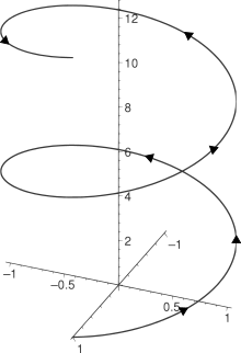
third ... the simple parts.
- 360o of the ramp of a cylindriCal helix is just a circular annulus, cut on one radius and raised to whatever height.
- (as pjt has shown) the wall of the cylinder from the base to the helix is just a triangle ... or a diagonal in a rectangle ... when the cylinder is unwrapped to flat. (like the wrapper around a tin of baked beans)
So you can produce the inside and outside vertical walls of (360o of) a helix by drawing a diagonal line on two rectangles and curling them into a circle.
And you can make the ramp by cutting an annulus and lifting it to the right height.
And being a rectangular cross-section helix is no problem because the two ramps are the exact same shape place above each other.
When I saw the table I immediately thought of the trick for drawing curves (on a flat surface) where - as an alternative to calculation - you take a flexible material, pin it at the ends and let it describe the curve.
The widening spiral will be similar (to the cylindrical case) I think ... just a matter of unwrapping a baked-bean can back to flat.
I'll think about that for a sec.
-
11th January 2014, 06:28 AM #33
GOLD MEMBER
- Join Date
- Aug 2009
- Location
- Armadale Perth WA
- Age
- 55
- Posts
- 4,524
This is overkill I know, but lots of good stuff here: http://mamikon.com/USArticles/RollingConesCylinders.pdf
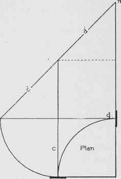
In particular ... an idea for thinking about the path the ramp will take in this table ... a trucated, inverted cone shape ...
unwrap cone.JPG
Unwrapping a cone to flat produces a section from a circle ... the slope height of the cone becomes the (flat) radius ... and the diameter around the base of the cone will tell you how much of the full (flat) circle you need.
Back to your table ... the question is how would that spiral/helix be described on the flat part-circle.
At first I thought that there were equal height increments at 0o, 90o, 180o, 270o, 360o, ... but after doing some drawing I don't think so, now.
Whatever the curve, once you know what it looks like, the heights can be marked out easily enough ...
Imagine the cone marked around the "rim" as A, B, C, ... at 0o, 90o, 180o, ...
Calculate the (constant) distance between letters around the rim.
Mark those letters at those distances on the flattened cone, along the circumference.
Transfer the heights at each letter to distances along the radius from the centre to each letter ... then join the dots and fluff in a curve.
-
11th January 2014, 06:54 AM #34
GOLD MEMBER
- Join Date
- Aug 2009
- Location
- Armadale Perth WA
- Age
- 55
- Posts
- 4,524
I think they've done a damn good job at designing the shape of the thing - even 'though I don't really like the table.
Do you want to create exactly this shape? The cylindrical would be easier!
I put up pictures of a french museum where they had a 17th C "CAD" device for similar problems ... I'm trying to think of what material you could use to model this easily ...

Once you know the top and bottom diameters for the (truncated) cone ... then you could have spacers and perspex 'washers' of the right successive diameters on a rod ... with a string attached to each 'washer' at one outside point ... so that you could turn them to different degrees to model different slopes.

My attempt at drawing a constant ratio of height to angle of rotation ...
The table seems more dynamic than that ... it seems to accelerate in height to me.
20140111_033815[1].jpg
-
11th January 2014, 07:38 AM #35
GOLD MEMBER
- Join Date
- Aug 2004
- Location
- Coffs Harbour
- Posts
- 2,018
Brilliant guys.
The theory now makes sense and I think the drawing of the forms is sorted.
The cyclone looks like it has potential as my form/mold.
I can make the height, top and bottom diameters to suit the table.
Then draw my triangle.
When I get back home I will start putting it together.
thanks.Scally
__________________________________________
The ark was built by an amateur
the titanic was built by professionals
-
11th January 2014, 05:56 PM #36
GOLD MEMBER
- Join Date
- Aug 2009
- Location
- Armadale Perth WA
- Age
- 55
- Posts
- 4,524
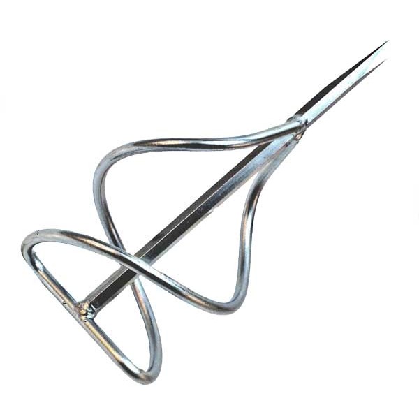
It occurred to me that it the shape almost looks familiar, and I was wondering what could have directly inspired it, if anything.
Best I've come up with so far are these mixing paddles ...


-
17th January 2014, 03:00 PM #37
GOLD MEMBER
- Join Date
- May 2007
- Location
- Sth Gippsland Vic
- Posts
- 4,399
Nice
-
17th January 2014, 06:25 PM #38
GOLD MEMBER
- Join Date
- Aug 2009
- Location
- Armadale Perth WA
- Age
- 55
- Posts
- 4,524
This looks a bit like the table to me ... could be wrong ...

There is a stair calculator that might help in modelling it???
Spiral Stair Calculator - Set Out Circular Curved and Spiral Stair Geometry - Metric
Cyclopedia Of Architecture, Carpentry, And Building Vol1-3Tangent System
shows a 'tangent method' of turning a general sweep and a height-rise into a 3D shape ...


another tricky spiral ...

Curved Stairs
-
17th January 2014, 06:32 PM #39
Skwair2rownd
- Join Date
- Nov 2007
- Location
- Dundowran Beach
- Age
- 76
- Posts
- 19,922

Some very sinuous stuphph there Paul. Really good finds.
I don't know about you but the tangent method is not my preferred
Method for drawing the helix.
-
17th January 2014, 08:16 PM #40
GOLD MEMBER
- Join Date
- Aug 2009
- Location
- Armadale Perth WA
- Age
- 55
- Posts
- 4,524
Interesting software + equations ...
Design Variable Pitch Helix by Equation Curve - Tips & Tricks - ZWSOFT.com


 Reply With Quote


Similar Threads
-
More Helix Clamps
By Anorak Bob in forum METALWORK FORUMReplies: 3Last Post: 11th August 2013, 11:31 PM -
Helix Clamps - A modification
By Anorak Bob in forum METALWORK FORUMReplies: 18Last Post: 31st January 2012, 11:08 PM -
Bit of help needed with the new table I just got
By perthmum in forum WOODWORK - GENERALReplies: 6Last Post: 3rd April 2009, 06:59 AM -
Help with table saw needed in the ACT
By Coffee in forum WOODWORK - GENERALReplies: 3Last Post: 21st March 2007, 12:29 PM -
Router Table needed
By Don Nethercott in forum ROUTING FORUMReplies: 36Last Post: 14th February 2006, 05:01 PM
