

 Thanks: 0
 Likes: 0
 Needs Pictures: 0
 Picture(s) thanks: 0
Results 1 to 15 of 46
Thread: Lets Design a Hand Plane
-
18th September 2008, 04:40 AM #1

 GOLD MEMBER


- Join Date
- Mar 2006
- Location
- Earth
- Posts
- 3,569
 Designing a Modern Dovetailed Hand Plane
A few members on the forum are planing to make their own infill/dovetailed hand planes. While there are some good resources on Norris style infill's. I am yet to find detailed plans for a more modern styled Dovetailed Hand Plane. To this end I have drawn out a very rudimentary concept for a bevel up smoothing plane, largely along the lines of a Marcou and Holtey No.982. I am hoping that more knowledgeable members can fill in some of the blanks, the why's and how's of plane construction. So as to design something with rhyme and reason.
The dimensions are only ball park figures as I have never had access to either plane. Dimensions are based largely on the Marcou, as I know that Marcou is just under 280 mm long, and that he uses an 8 mm sole (Marcou suggests starting with 9.5 mm (.3750", 3/8) O1 for the sole, because penning and lapping will rapidly reduce the plane sole to 8 mm), a 6 mm side and a 1/4" 28 TPI imperial thread on the adjuster, and the plane cheeks are somewere between 50 to 60 mm high.
I however have some questions that have been nagging me for a while:
- Why is it that no manufacturer makes a bevel up plane with a bedding angle greater the 20º? Is their a problem with such a step bevel up approach?
- How could cross bar secured to the cheeks (penned, threaded or free floating)?
- Metric versus Imperial thread? Is there any advantage of using one over the other. I ask because of a comment by Marcou were he says "imperial being a well made thread (as opposed to the metric)." Any suggestions to what he means by "well made thread"?
Attached are my preliminary drawings and the pdf.
Attachment 83864
Attachment 83871
Attachment 83872Last edited by thumbsucker; 18th September 2008 at 12:23 PM. Reason: Streamlined by questions (to much Coffee)
-
18th September 2008 04:40 AM # ADSGoogle Adsense Advertisement
- Join Date
- Always
- Location
- Advertising world
- Posts
- Many
-
18th September 2008, 02:37 PM #2
hardly human

- Join Date
- Jun 2005
- Location
- Sydney
- Posts
- 3,096
hmmm,
had a look at your drawings... not sure if I understand them totally, which is the problem with 'preliminary drawings'
So, I have some questions:
- how does the blade adjuster attach to the body of the plane?
- the tote... is the drawing to scale? Seems that there isn't much material for the tote to screw into, and it seems to have only one attachment point?
- will the sole be a 2 piece or single piece, and how many dovetails will there be?
- Dovetails or pins?
- do you want a beautiful tool... or are you happy to sacrifice some of the 'looks' for ease of manufacture?
My 2c worth:
- "cross bar" I peen them when doing an infill, but I see the benefits to using thread and loctite but have no experience in the durability of a thread cut in brass for this purpose.
- You seem to want a "more modern design", well, my question is "whats the difference"?
Not being a smart ?????... I think its an important question.
Are the differences:
- stylistic,
- based on manufacture techniques,
- availability to resources,
- and a whole slew of other 'ponderings'.
I think you should also apply the same process to "why were the older planes made the way they were?"
Also identify what you consider to be important. e.g. if you want to shoot with it, a coffin style isn't what you want, and you might want a mouth that extends all the way across the sole like the LN Mitre plane.
Do you consider:
peening through the sole to attach a "solid frog" that stands about 10-15mm proud of the sole plate, handle 'block' and adjuster mount?
Is welding an option?
Why brass sides?
Why not use rare earth magnets for some mountings (outlandish, I know... but worth considering)
BTW - the curved versus right angle question for the lever cap? Drill then use a hacksaw, or use a hacksaw and file, or use a milling machine with a straight or rounded cutter head... or just mill/file a groove.
See, sometimes techniques lead to questions... but my assumption of a different technique affects my 'framing' of the problem/option.
Your requirement might be for a 'thing of beauty' and you may have the 'attention to detail' required to achieve it, whereas I loose interest quickly and might just tack weld some mild steel together, use a wedge over a lever cap for convenience, lap the sole and decide its done!
So, what do you want to achieve? What resources do you have to achieve it with? I'm happy to participate, but need to know what your requirements and resources are.
Long post, I know... brevity eludes me, except when making smart ???? remarks.
-
18th September 2008, 03:31 PM #3
Moderate Moderater
- Join Date
- Feb 2006
- Location
- Lindfield N.S.W.
- Age
- 62
- Posts
- 5,643
Helmut
Clinton raises some interesting questions, which I will duck because I can see little point in dissuading you from trying to build your design!!
However, on the issue of the round v right angled issue, I agree that the technique Clinton suggests will get you the round matching face and I think that is likely to be a better way to get a bearing surface than the right angle. It shouild be a suface that doesn't move around even slightly as the angle of the cap is changed by tightening the screw.
On the question of the bedding angle, I think that 60 degrees total is a bit too high for a smoother. The higher angle is really for when you are dealing with gnarly Aussie hardwood. If you really want it to be a BU smoother then the bedding angle needs to be such that the included angle is between 40 and 50 degrees (so if it is a 30 degree edge bevel, the bedding angle should be 10-20 degrees). I refer to edge bevel, because the issue is the angle at the edge, not the primary bevel, so 30 will be right for a 25 degree primary with a 5 degree secondary/micro bevel.
However, I was wondering if a better idea might be to use the HNT Gordon system - have your blade reversible (so long as your adjuster connects to the blade via a round pin, the same holes will work on it). Then if you have a 35 degree bedding angle you will have a low angle smoother with the blade BD, that you can convert into a high angle plane to deal with horrible grain by flipping the blade over.
As for peening or screwing, I would peen. If the rod is a close fit in the cheek holes and there is a little countersink on the outside of the cheek holes, it will hold more than adequately and it is easy to take apart if you need to (I did when I needed to up the diameter of a rod). A dremel can grind the peening off really fast. Remember the rod is not uncder any real forces along its length so all we are doing is making it pretty and keeping it still.Cheers
Jeremy
If it were done when 'tis done, then 'twere well it were done quickly
-
18th September 2008, 04:44 PM #4
GOLD MEMBER
- Join Date
- Mar 2006
- Location
- Earth
- Posts
- 3,569
The overall aim is to make a functional tool that is beautiful whose sole function is as a soother
of gnarly Aussie hardwoods.
I am bound to offend some however:
I am opting for a bevel up because I feel that this is where hand plane technology is going.
I want a bevel up, because I have enough of bevel down planes. I have very good results from the Veritas Bevel Up range, but I hate the tote due to the cramps in the palm. The aesthetics is not crash either.
I do not like the look of old styled infills.
Norris and kin are a product of their times and technology.
"The basic problem of infill design remains that the plane is vulnerable to the dimensional instability of wood". - Holtey
I will dovetail the plane this my concession to nostalgia.
I will use a milling machine to machine the parts, I am a Sadist not a masochist. (I will be going back to school next year and will have access to all the machines I need.)
Clinton the remaining questions will be become clear as I finish in the details and yes I have a few blank spot in the details. This is were research will come in.
I think thread and loctite maybe the way to go. Since it is a non moving part held in place by thread, loctite and the cheeks.
 Is it not the aim of a smoother to smooth those patches of gnarly grain that are resistant to the work of the fore, and jointing planes. jmk89 the bed rests at 30º, the primary bevel is at 25º and the secondary bevel (edge bevel) is at 30º for an effective cutting angle of 60º. The same angle as the HNT Gordon Smoother (My favorite hand plane to date).
-
18th September 2008, 06:00 PM #5
GOLD MEMBER
- Join Date
- Jun 2008
- Location
- Victoria, Australia
- Age
- 74
- Posts
- 6,132
Hi Helmut,
All good reasons, I am going for a more traditional design, I like the look of the one Peter (aka Lightwood, creator of the Skint McBride range of woodies..) has on the front on the HTPAA newsletter. (except mine will be better..") )
)
I am planning to ditch the adjuster, Sort of like an A6 without the "A" and keep it simple. The lever cap screw I am just now playing around with ways of making it. (I have a lathe, and now I have some knurling tools, everything lately is knurled...) but I don't know what thread to use. I was intending to use acme thread, but the price of acme taps is ridiculous. (I know peter makes his own.)
Just a side note, nobody makes acme dies. Not practical apparently.
So, what thread for the lever cap.. I am going to have a look at 3/8 x26 tpi.
I see on your drawing that you have a pad on the bottom of the screw. Good Idea. Consider it pinched.
Regards
Ray
-
18th September 2008, 06:30 PM #6
GOLD MEMBER
- Join Date
- Mar 2006
- Location
- Earth
- Posts
- 3,569
Thanks for the PM Clinton.
Yes you are right when you say "I reckon you might have a pretty clear idea of the design, and may just be looking for specific questions to be cleared up". I have a very solid idea of what I want to go with and why. I however have no idea about the million and one little details.
Stuff like how thick should this be and how long should that be, and how many TPI should this thread have, and how far apart should the dovetails be. etc etc.
The only solid stuff I have is the overall length, blade thickness, cheek and wall thickness. However beyond that, I am looking at photographs, comparing sizes of known components and guesstimating the dimensions of the other components.
I will keep working on the drawing filing in some of the parts missing as you pointed out. Then I will come back with some more questions for you.
Any help that you an other can give in line with the above would be much appreciated.
In regards to your PM, I would want to learn how to cast bronze when I continue my studies. There are many shapes and sizes that can only realistic done with castings.
Cheers
Thumbsucker
-
18th September 2008, 06:40 PM #7
GOLD MEMBER
- Join Date
- Mar 2006
- Location
- Earth
- Posts
- 3,569
That is another reason why I started this thread, so that all those blokes can draw together, and gain just these little things. I have been collecting photos for over a year now and studying every little detail. Originally Posted by RayG

I known that Marcou uses 1/4" 28 TPI for the adjuster, I would assume, that 4/8 26 TPI for the lever cap maybe on the high side, is the leaver cap a fine adjustment tool? But then I do not known. It could be valuable to be able to progressively increase pressure thank to a finer thread?
Would the lever cap bolt be one of the more stressed components? Would a finer thread on a heavy stress part be more prone to wear or breakage?
Many many questions.
I had my lever cap bolt at 8 mm I will increase it to 10 mm, as its closest to a 3/8".
-
18th September 2008, 07:02 PM #8
Peter McBride
- Join Date
- Nov 2007
- Location
- Melbourne
- Posts
- 1,139
TS,
Some may have realised I'm very much a traditionalist with infill plane making. So blocky looking planes, with modern levers and adjusters don't get my juices going. I know some like them, but like gravy on your potatoes...some yes some no.
I think this plane making exercise might be approached from another perspective. When I started making jewellery 30+ years ago, I had limited skill, and very basic equipment, so I designed items that fell within my skill base and equipment on hand. As I sold more I could afford more equipment and my skills increased. Now whenever I make something, be it a staircase, a kitchen, an art deco style diamond ring, or a hand plane, I look to my skill base, and equipment very early in the design stage. This is a philosophy of work, if you will, that when applied with a thirst for more hand skills, has served me very well.
A few basic assumptions, since this is predominantly a woodworkers list...(and I'm more than happy to be corrected here)
1. no milling machine.
2. no metal lathe.
3. average to low metal working skill.
4. average to high woodworking skill.
5. good capacity to learn new skills, understand the principles and apply them accurately fist time.
6. when something is going wrong and the idea is dropped, to catch it before it hits the ground.
Ever since I tried to use an "A" Norris plane I was less than impressed with the adjuster...set the depth, tighten the lever, loosen the lever adjust the blade, tighten the lever, loosen the lever adjust the blade...darn...get the camera, take a picture and list it on ebay for sale.
Here is my Favorite Norris plane with its adjuster.
Don't just take my word for it, Wayne Anderson and Ron Brese discuss it in this thread
Wayne said...."Thank you Ron. I am not as much concerned with the looks of an adjuster as with the actual need for one. I'm just glad Norris didn't decide to add little headlights to their planes, or I would be getting requests for that "must have" option as well -wayne
Ron Brese "Amen!!"
I can make a double threaded Norris adjuster including the left hand thread, and I once filed by hand the double start left hand thread on a Stanley block plane adjuster, but wouldn't bother putting it on an infill plane when it is so woefully inadequate, even if my skill base and equipment could support it.
The base.
Bevel up planes need about a 1.0mm throat opening, so that means two pieces or an adjustable throat with lots of pieces!. Bevel down can be cut with the base in one piece, but a block riveted behind the throat to support the blade (Spiers) is a good option. Removing 1.0mm of thickness of O1 toolsteel base will be a nightmare without a mill.
The lever.
Looks to me like a removable lever under a pretty high pin is needed to get the blade in past the handle on those bevel up planes. That blocky lever by Marcou is a function of that problem.
To quote Philip Marcou. "I am definitely not of the hammer hacksaw file and shifting spanner brigade."
Well I am, having used a couple of shifters to get the sides on this plane square to the base, and used hacksaw, hammer and files almost daily for 30 years. I think most of the enthusiastic amateurs like me, are also members of the brigade.
I have an interesting variation on the removable lever that has hooks underneath...seen here and here. It might be able to be adapted to the bevel up plane. Another option to get the blade in would be to use steel lugs in each sidewall instead of the pin all the way across.
I think it is a far more pleasing looking treatment, compared to what I think is a pretty agricultural solution, to mill a block out of the brass and tuck it under a pin.
Even Preston added a little stylish treatment to their unique lever under a pin infill plane
As you may have realized, if you have got this far into my post without hitting the delete button, I'm very much a traditionalist with infill plane making. So blocky looking planes, with "modern" levers and adjusters don't get my juices going.
I would encourage any prospective plane make to try and get the opportunity to pick up a nicely rounded unhandled small smoother, and see how comfortable it is in the hand. They are probably the simplest to make and will be a very rewarding plane to use.
If a huge angle of attack is wanted 50 or 60 deg, I would go for a bevel down, single iron...it can be functional AND beautiful...in my eyes anyway...see the link above to view Wayne' Anderson's latest offering. (and seek out a review of his high angle smoother in the latest PWW mag)
Screw threads for lever cap screws are traditionally 14 TPI square thread, not the angled acme, 7/16 Whitworth is 14 TPI. I've used the 1/2 whit and found it a bit fast, and prefer the feel of locking down with 14 TPI...This is pretty similar to a M12 I think from a quick calculation. The pad on the bottom of the lever is so it won't foul in the holes in the blade for the adjuster pin.
More later on this as time is available...except...as the owner of more than 80...and the maker of 7 traditional dovetailed and cast infill planes for my own use, I know they are completely stable enough to serve well for 150 + years, and ...sorry...but to state otherwise and to recommend design decisions on that, is simply a mistake.
PeterLast edited by lightwood; 18th September 2008 at 07:06 PM. Reason: spleeing again
-
18th September 2008, 07:32 PM #9
GOLD MEMBER
- Join Date
- Mar 2006
- Location
- Earth
- Posts
- 3,569
Thank you for your information on the lever cap screw count. I thought 24 TPI sounded a little high.
I view this as a long term project, I am giving myself, 1 to 2 years to finish it.
I am also not a fan of the blocky infill's, modern is not blocky. There are some classical infill I do not mind and I am rather attracted to the Anderson's. However that is Anderson's story. I think the Bedrock lines are very classical and have a timeless appeal to me.
It is clear that we stand almost opposite on the aesthetics scale. I do concede that the Marcou lever cap is rather chunky. I will try to elongate its lines a little.
I am considering dropping the bedding angle to 20º, I can always makes up the angle of attack with the blade.
I am amazed how you get the lap joint in the mouth, do you solder it after words?
I will be opting to mill the mouth like Anderson.
-
18th September 2008, 07:50 PM #10
hardly human
- Join Date
- Jun 2005
- Location
- Sydney
- Posts
- 3,096
Peter,
1. no milling machine.
2. no metal lathe
I will use a milling machine to machine the parts, ... snip.... I will be going back to school next year and will have access to all the machines I need
-
18th September 2008, 08:22 PM #11
Moderate Moderater
- Join Date
- Feb 2006
- Location
- Lindfield N.S.W.
- Age
- 62
- Posts
- 5,643
Peter and Helmut and others
One of the issues with all of this is, as Peter put it so well, some of us like gravy on our spuds and some of us don't.
That's why I addressed what I considered the technical issues of Helmut's design.
So I like Norris adjusters and I reckon that Jim Kingshott got it just about right with the fine thread to stop the backlash.
What I didn't address is why Marcou seems to say that metric is less robust than imperial. I don't know why he said that. I reckon that whitworth is as robust as metric (after all they have the same angle to the sides of the thread) - maybe the contrast is between 60 degree and 55 degree sides.
If you want robust in a thread then go for Acme or square, but then it won't be fine.
I reckon that if you have a robustness issue with a thread the solution is rarely the thread form, but is more often the material - so go up from brass to steel and from mild steel to silver steel and the tread will become stronger, but more brittle.Cheers
Jeremy
If it were done when 'tis done, then 'twere well it were done quickly
-
18th September 2008, 08:45 PM #12
GOLD MEMBER
- Join Date
- Jun 2008
- Location
- Victoria, Australia
- Age
- 74
- Posts
- 6,132
And jmk wrote Originally Posted by lightwood
.If you want robust in a thread then go for Acme or square, but then it won't be fine
Hi Peter & Jeremy
Thanks for the clarification I always thought acme thread was square shouldered, I found a good drawing of the acme profile here
http://www.diracdelta.co.uk/science/...ad/source.html
I think 7/16 14tpi whitworth is what I will use for the level cap screw.
Regards
Ray
-
18th September 2008, 09:21 PM #13
hardly human
- Join Date
- Jun 2005
- Location
- Sydney
- Posts
- 3,096
Helmut,
Got a copy of the Machinery's Handbook... or can you get one from the TAFE or local library?
Might give you some strength info for the various threads.
In fact, if you have not taken a look at it, I can't rate it highly enough. It is a reference book and an absolute goldmine of info.
Machinery's Handbook, Industrial Press, ISBN-10 0831127007 or ISBN-13 978-0831127008
And see this guy if you need cheap (secondhand) taps and dies, or any other tooling... he's helpful and will post.
-
18th September 2008, 09:45 PM #14
Peter McBride
- Join Date
- Nov 2007
- Location
- Melbourne
- Posts
- 1,139
TS, Originally Posted by thumbsucker
Yes we are at different ends of the plane aesthetic...the spice of life isn't it??
As for Anderson, all his planes have the T&G joint at the throat...to quote him...
I use a T&G joint in all my planes. No one has explained to me how to machine this feature from a solid bar yet. I only have a small milling machine, and I do not outsource any of my parts...in otherwords, the entire plane is completely handmade by me.
Someday I may get bids on parts for those worthless adjuster gizmos, but I still make those too.
-wayne
That joint is surprisingly easy, Here is one that I made on my skew mouth chariot. I would do it slightly different next time though...see below.
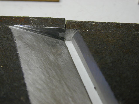
On the skew mouth plane the groove is a little difficult, but without the metal in the way the groove is cut in bothe sides with a few strokes of a hacksaw,(remember it is only about 6 or 7mm wide on each side) and then I open it up with a needle file..1/3 - 1/3 -1/3. Then I cut the tongue, and file with a smooth flat file...again it is only about 6 or 7mm. Then a few raps with a hammer on the end of the bed and it seats home, and if the tongue spreads the groove a little, just tap it down some and file the top flat. There is no solder in it. When it's done you can pick the base up and it is locked pretty tight. Note: on the one above the top of the groove is aligned with the back of the throat, I wouldn't do it that way again. I would make that stick out as much proud as the desired throat opening, say 1mm, and make the front of the throat flush, with the tongue proud of that. I think I will be able to control the throat opening a little easier that way.
Although I may have posted it elsewhere on this forum, this link might help some. Dimensioned drawings and close-up pictures of a Spiers mitre plane.
Any requests for the same type of page for smoothers are welcome.
I have a few
Regards,
Peter.
www.petermcbride.com/planemaking/
-
19th September 2008, 01:11 PM #15
GOLD MEMBER
- Join Date
- Apr 2006
- Location
- near Mackay
- Age
- 59
- Posts
- 4,635
Hi All, have just been looking at the (latest?) copy of "British Woodworking" magazine , issue #6.
It has an article about Bill Carter, and his planemaking activities. In the article he describes how to make a dovetailed mitre plane. There is also a bit of detail on the T&G joint he uses for the mouth.
He has a website, might be worth a look , http://www.billcarterwoodworkingplanemaker.co.uk/
Not sure if he makes smoothers, but some good info there relative to the topic.

 Reply With Quote


Similar Threads
-
hand plane
By kmthor in forum HAND TOOLS - UNPOWEREDReplies: 8Last Post: 25th June 2008, 10:47 PM -
Is this an old hand plane? Or not?
By mbirnios in forum HAND TOOLS - UNPOWEREDReplies: 7Last Post: 14th April 2008, 08:34 PM -
New Plane Design
By Scribbly Gum in forum HAND TOOLS - UNPOWEREDReplies: 3Last Post: 23rd May 2007, 02:59 PM -
Lets design a clamping jig
By LineLefty in forum HOMEMADE TOOLS AND JIGS ETC.Replies: 36Last Post: 12th November 2004, 10:36 PM -
Hand Plane
By TOMARTOM in forum HAND TOOLS - UNPOWEREDReplies: 7Last Post: 4th November 2001, 08:25 PM
