

 Thanks:
  Likes:
  Needs Pictures: 0
 Picture(s) thanks: 0
Results 1 to 11 of 11
-
4th December 2019, 01:56 AM #1
 SENIOR MEMBER


- Join Date
- Oct 2019
- Location
- Brisbane, Australia
- Age
- 43
- Posts
- 519
 Diagnosing problem with hand plane
Hi I'm new to hand planes generally but decided to pick up a couple on ebay/gumtree and try and learn the basics slowly.
I bought a No 4 and No 5. Having a lot of luck with the No 4 and enjoying learning.
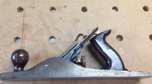
But I can't seem to set up the No 5. I took it apart and when I set it up, the thrust wheel (adjusting nut) is pushing right through the "Y" adjusting lever. I don't know if it is obvious on the photos but the adjusting nut just pushes the Y-lever to the side and moves through.
I've attached photos. Is this the problem; and do I just order a new "Y" adjusting lever to fix this?20191202_203403.jpg20191202_203350.jpg
"Y" ADJUSTING LEVER
-
4th December 2019 01:56 AM # ADSGoogle Adsense Advertisement
- Join Date
- Always
- Location
- Advertising world
- Age
- 2010
- Posts
- Many
-
4th December 2019, 02:32 AM #2
Be inspired. Be creative. Be bold.
- Join Date
- Apr 2001
- Location
- Perth
- Posts
- 10,824
Simple solution: the Y-lever is meant to ride between the ring and the wheel (and not on the ring)..
The Y-lever is pushed-pulled by these two parts.
Regards from Perth
DerekVisit www.inthewoodshop.com for tutorials on constructing handtools, handtool reviews, and my trials and tribulations with furniture builds.
-
4th December 2019, 05:56 AM #3
SENIOR MEMBER
- Join Date
- Jan 2010
- Location
- Auckland New Zealand
- Posts
- 312
Just bend the legs of the adjustment lever inwards so that they stay put inside the groove on the brass adjustment nut.
-
4th December 2019, 08:16 AM #4
Butcher of wood
- Join Date
- Jun 2010
- Location
- Bundaberg
- Age
- 54
- Posts
- 3,428
I suspect the issue may have been caused by having the lever cap on far too tightly.
Pull the plane apart again, including removing the frog from the base.
Firstly, as Botesmj1 says you may need to GENTLY bend the arms of the yoke so that they fit inside the groove of the adjusting nut. By removing the frog you can do this in a vise if you have one; you want the arms of the yoke to fit inside the groove in the nut as shown in Derek�s picture.
Screw the frog back into the base, as it is a later design you�ll find that it can twist and flop around alarmingly. You want the frog to be central, square and flush with the bevel on the mouth opening.
Replace the blade and cap iron assembly, note that the blade must fit over the round projection of the lateral adjustment lever and the rectangular slot in the cap iron must fit over the projecting end of the yoke. At his time you want the blade to be just inside the mouth with no part sticking through just yet.
Back off the screw that holds the lever cap a couple of turns and then replace the lever cap. At this point it should be a pretty sloppy fit. Gradually tighten up the screw until the lever cap is gripping the assembly but can be released easily. When the lever is pulled up there should be zero clamping force and the cap should be loose, but as stated earlier you have a later model so a tiny amount of clamping force may be present; it depends on how well the cam on the lever was formed.
Now test the adjustment, the blade should be able to be moved with minimal torque on the nut. If the knurling is coarse enough a single finger should be enough.
Next time you go plane shopping look for pre WW2 US models; once you�ve set up and used one of those you�ll never go back! THIS website gives you the general model history.Nothing succeeds like a budgie without a beak.
-
4th December 2019, 09:48 AM #5
SENIOR MEMBER
- Join Date
- Oct 2019
- Location
- Brisbane, Australia
- Age
- 43
- Posts
- 519
Many thanks, Chief Tiff.
I will give this a go tonight, and bear the advice in mind!
- - - Updated - - -
Thanks mate - much appreciated.
-
4th December 2019, 02:31 PM #6
Be inspired. Be creative. Be bold.
- Join Date
- Apr 2001
- Location
- Perth
- Posts
- 10,824
I would not attempt this - the y-lever will break. Originally Posted by botesmj1

This issue is not a brain-breaker. But it is something that the inexperienced may find occurring. It is simply about re-assembling incorrectly. Just take it apart and reassemble with the y-lever between the two sections of the wheel.
Regards from Perth
DerekVisit www.inthewoodshop.com for tutorials on constructing handtools, handtool reviews, and my trials and tribulations with furniture builds.
-
4th December 2019, 03:56 PM #7
Senior Member
- Join Date
- Nov 2008
- Location
- usa
- Posts
- 161
It looks like he's got the later, two piece stamped yoke. Those can be bent around quite a lot. If it's the older, cast iron type they're pretty fragle. Originally Posted by derekcohen
Occasional musings on my blog:
bridgerberdel.wordpress.com
-
4th December 2019, 06:38 PM #8
Butcher of wood
- Join Date
- Jun 2010
- Location
- Bundaberg
- Age
- 54
- Posts
- 3,428

It�s definitely the later pressed steel yoke; looking closely at the original pictures it appears to have been bent further open so that the ends can be forced in and out of the groove of the adjusting nut. This is why I believe the root cause of this issue was a way too tight lever cap; it can be so tight that the yoke and/or the pivot pin deforms rather than moving the blade assembly.Nothing succeeds like a budgie without a beak.
-
5th December 2019, 08:08 AM #9
GOLD MEMBER
- Join Date
- Mar 2004
- Location
- Brisbane (western suburbs)
- Age
- 77
- Posts
- 12,126
Or possibly someone didn't figure out how to feed the ends of the "Y" into the slot as the thumb-wheel is screwed onto its stud & opened it up a bit deliberately? Originally Posted by Chief Tiff
Derek, I certainly wouldn't try squeezing a cast yoke too vigorously, but I don't think they are 'cast iron' as I've often seen stated, which would snap like a carrot at the least provocation. I think they are a far more malleable alloy than that used for the bodies. Years ago, in an early FWW, I read an article on fettling Bailey planes (the first time I came across that word applied to planes), in which the author advised bending one arm of the yoke back to reduce backlash. I've always wondered how many yokes got broken as a result of that bit of advice...
One of my early acquisitions had a badly-bent pressed (two-piece) yoke, and at that stage you could still buy the cast variety easily - I just ordered it from the bloke at my local friendly hardware store & it was there in a week. They cost very little at the time, so I bought two, & kept the other as a spare. The spare is still looking for something to do 30 years on....
Cheers,IW
-
6th December 2019, 06:44 AM #10
SENIOR MEMBER
- Join Date
- Oct 2019
- Location
- Brisbane, Australia
- Age
- 43
- Posts
- 519
Gents, just a follow-up.
Looks like it did the trick but won't have a good chance to do some "schlicks" until I get a chance to tune it up.
I took the wheel out, fitted the "Y" as shown in the helpful photo, and put back together. It still felt very loose but I gave it a light finger-tighten and it tightened where it should be. It still feels a bit loose and isn't really locked in by the ring in front of the wheel, but in the range where it does move I get plenty of adjustment (blade moves down a few mill below throat which should be all I need). Photo below.
From an untutored look and feel, it seemed to be some kind of alloy and not cast iron - definitely had play even with just finger tightening.
I'll give the blade a trip around the stones this afternoon and hopefully a little test run shortly after!
20191206_053308.jpg
-
7th December 2019, 09:46 PM #11
On a journey
- Join Date
- Oct 2008
- Location
- Leopold, Victoria
- Age
- 65
- Posts
- 4,683
Looks like the yoke is only pressed steel so you should be able the squeeze the legs in until it is a neat fit on the nut if it looks like it is going to jump over the collar, but don't make it a tight fit on that cylinder, leave some play.

 Reply With Quote


Similar Threads
-
Can I trim a #6 hand plane & use as a #5 1/2 jack plane? Your opinion needed
By woodhog in forum WOODWORK - GENERALReplies: 9Last Post: 16th May 2017, 12:32 AM -
Diagnosing blade issue
By masher in forum BANDSAWSReplies: 2Last Post: 23rd January 2017, 09:00 PM -
Hand Scraping a Hand Plane to .0001" Accuracy
By Ulma Doctor in forum METALWORK FORUMReplies: 4Last Post: 28th February 2015, 06:38 PM -
help diagnosing my problem
By welder in forum THE HERCUS AREAReplies: 26Last Post: 7th November 2010, 02:53 PM
