

 Thanks: 0
 Likes: 0
 Needs Pictures: 0
 Picture(s) thanks: 0
Results 1 to 15 of 16
-
9th August 2010, 11:47 PM #1
 GOLD MEMBER


- Join Date
- Jun 2008
- Location
- Victoria, Australia
- Age
- 74
- Posts
- 6,132
 Thinking of making another Infill
Hi All,
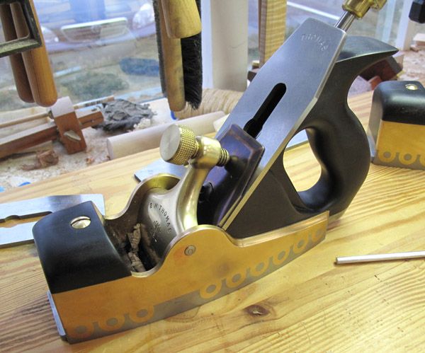
I stumbled across an interesting infill the other day, and it got me started down that slippery slope, of making another infill, the fun of making the last one has me hooked forever... but what intrigues me about this one is exactly how it was made?
The Return of the "Loopy" Infill Plane by Chris Schwarz
How do you make the loops? Is the brass peined?
I'm hoping that Peter McBride will know the answer to this one....
Regards
Ray
-
9th August 2010 11:47 PM # ADSGoogle Adsense Advertisement
- Join Date
- Always
- Location
- Advertising world
- Age
- 2010
- Posts
- Many
-
10th August 2010, 01:09 AM #2
Heavy Machinery
- Join Date
- Mar 2008
- Location
- Lambton, Newcastle, NSW, Australia
- Posts
- 4,957
Beautifull plane Ray, that would keep you off the streets for a few days. The mouth plate and housing would be a bit tricky. The guy writing the artical said he doesn't like Noris adjusters, I love my Noris adjuster, smooth as silk, no backlash or slop.
Have fun
-
10th August 2010, 01:28 AM #3
Senior Member
- Join Date
- Nov 2008
- Location
- Melbourne, Australia
- Posts
- 275
I remember something about this from a while back. Did someone else post about this?
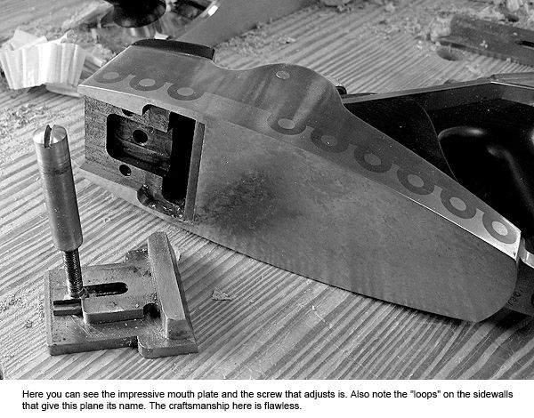
Anyway, my recollection is that the base is very thick and that the loops and their mating eyes were cut using a CNC mill to very fine tolerances so that the brass was an interference fit to the steel base with no peining required.
If it is the same bloke involved, I think he was trying to make a joint that would be at least as servicable as the dovetails that others were using but could be entirely machine cut.
I don't have a super-clear memory of this plane but I remember a similar article that sparked my interest. At the time it grabbed me because it reminded me of a project I had been involved in a few years ago where engineers who worked on the US space program helped us do a very short run of an uprated part for our vintage motorbikes. I kid you not!
-
10th August 2010, 11:52 AM #4
Peter McBride
- Join Date
- Nov 2007
- Location
- Melbourne
- Posts
- 1,139
Ray, Originally Posted by RayG

I do recall reading about the plane years ago, but don't recall the method used to make it, other than it was pretty much machine made and hand finished..
HOWEVER....I always look at making anything with a clear idea of what tooling I have at my disposal. I don't much care for subcontracting out parts of the process, that just gives the fun away to someone else.
First thing is...it has a very thick base plate, so the sides could stay at 3mm or 1/8 without compromising weight. That makes hand work on the sides MUCH easier than the 6mm or 1/4 in stuff in your last one. So I would look at making a unique design, not identical to that one, but one which will be achievable with the tools you have. (Like using the correct profile gouge or file to get the desired shape easily), you could combine drilled holes, saws and files to make a pattern on the sides, then use endmills in the drill press to get the sides of the base cut out. The center pin ( or multiple pins in the one feature) could be separate threaded pins screwed into drilled and threaded holes done after the sides are on the plane.
Thinking about it a bit like chip carving with round elements can open up lots of design possibilities.
If the sides do break through the bottom of the base ( unlike the one in the article), you can then use a saw and files to cut through after using an endmill.
Just a few thoughts...I will let it sit at the back of my head for a while and see what comes up.
Regards,
Peter
-
10th August 2010, 04:39 PM #5
GOLD MEMBER
- Join Date
- Jun 2008
- Location
- Victoria, Australia
- Age
- 74
- Posts
- 6,132
Hi Peter, Originally Posted by lightwood
Couldn't agree more... why let someone else have the fun ...
Since the last one, I have expanded the metal working capabilities a fair bit, I can now do cast bronze (gettitng better slowly) and have a HM52 mill (being converted to CNC). So casting and milling the parts for an new plane are now within the scope of the workshop.
And NO the idea of using the CNC mill is not to make tools, it's being setup to make parts for my son's artwork projects.
I still prefer the hands on philosophy. Maybe a bit like the manufacturing approach used by Holland and Holland, keep the CNC in it's place...
I won't be starting this project till later in the year, plenty of time to consider how to go about making the loops.
One advantage of the thicker sole, is it makes for a nice solid adjustable mouth mechanism.... I wonder.....
Regards
Ray
-
10th August 2010, 05:17 PM #6
Be inspired. Be creative. Be bold.
- Join Date
- Apr 2001
- Location
- Perth
- Posts
- 10,826
Hi Ray
I found this link ...
Smoothing Plane - Fine Woodworking Photo Gallery
I have had a fascination for the Loopy for many years. A bit out of my price range ($10000 - yes, $10K). One of my interests was for the adjustable mouth, since I am building an infill block plane with one.
I am sure I have more, but they will be on another computer.
Edit: dug up a few links I had unearthed years ago. These are on the construction (machining) of the Loopy!!
http://www.practicalmachinist.com/vb...-stamp-142511/
http://www.practicalmachinist.com/vb...project-85539/
Regards from Perth
DerekVisit www.inthewoodshop.com for tutorials on constructing handtools, handtool reviews, and my trials and tribulations with furniture builds.
-
10th August 2010, 05:22 PM #7
Peter McBride
- Join Date
- Nov 2007
- Location
- Melbourne
- Posts
- 1,139
Ray, Originally Posted by RayG
I saw this blokes work in wood, and have been wondering how to adapt it to the dovetailed plane idiom.
http://www.eurus.dti.ne.jp/~k-yazawa/trick.html
I have a picture in the #191 FWW mag showing how its done (can send it) , and I believe it's possible to adapt it to work in brass and steel....especially with a thick sole plate.
What about a partially sunk captive knurled wheel, about 45mm dia. in the infill at the front facing forward, to open and close the throat, and a domed knob at the top of the bun to loosen and tighten. Perhaps both decorated with the same motif as the sides.??
Here are some pictures of a Chaplin's original patent plane with the 1888 patent "T" throat adjuster.
Regards,
Peter
-
10th August 2010, 07:08 PM #8
The Laird
- Join Date
- Jan 2007
- Location
- Katoomba NSW
- Posts
- 4,774
That type of joinery would look amazing on an infill. Better than the Loopy IMO. Originally Posted by lightwood
-
10th August 2010, 10:18 PM #9
GOLD MEMBER
- Join Date
- Jun 2008
- Location
- Victoria, Australia
- Age
- 74
- Posts
- 6,132
Hi Derek, Originally Posted by derekcohen
Thanks for that, interesting reading. I can imagine how hard it would be machining brass free hand with a router! He must have nerves of steel. His flooring work is just beautiful as well.
Now, what it this adjustable mouth infill of which you speak?
Regards
Ray
-
10th August 2010, 10:29 PM #10
GOLD MEMBER
- Join Date
- Jun 2008
- Location
- Victoria, Australia
- Age
- 74
- Posts
- 6,132
Hi Peter, Originally Posted by lightwood
I have that issue of FWW somewhere, I must dig it out and see how that joint was done, it's very impressive looking. I agree with NC Archer it would look good on an infill. Free's up the design process a bit.
Does that Chaplin adjustable mouth have an adjustment screw, or do you just unlock it and slide it into position.
Regards
Ray
-
10th August 2010, 11:25 PM #11
gravity is my co-pilot
- Join Date
- Apr 2010
- Location
- Melbourne
- Posts
- 562
Could you lob it to me as well please? Originally Posted by lightwood
cheers,
BD.
-
11th August 2010, 01:04 AM #12
Peter McBride
- Join Date
- Nov 2007
- Location
- Melbourne
- Posts
- 1,139
Ray, Originally Posted by RayG
It is just a case of unlock and slide...so it's inevitable the iron is hit as the throat is closed up just that little bit too much
On the fancy dovetail, the more I think about it, the more I like the way it could be free-form or even perhaps a story could be told along the side of the plane.
Regards,
Peter
-
11th August 2010, 01:05 AM #13
Peter McBride
- Join Date
- Nov 2007
- Location
- Melbourne
- Posts
- 1,139
BD, Originally Posted by Blue-deviled
will do,
Peter
-
12th August 2010, 03:37 PM #14
Senior Member
- Join Date
- Nov 2008
- Location
- Melbourne, Australia
- Posts
- 275
Good stuff Derek, this was what I saw some time back. As usual, time has muddled my recollection. The reason he did the loops was that it wasn't possible with most CNC setups and he wanted to make it clear that the plane was an artisan item.
I did recall correctly that it wasn't peined though!
If I had the tooling I'd love to have a go at something similar. Maybe when I retire.
Peter, I love that box design. I've been thinking of carving a relief pattern in the door frame for my new shed, but that joint type would look so good on a tool chest, I just have to try it . I subscribe to FWW but I can't seem to locate that issue . If possible could you send a copy of the article my way?
Good thread!
Cheers
Horaldic
-
12th August 2010, 03:52 PM #15
Peter McBride
- Join Date
- Nov 2007
- Location
- Melbourne
- Posts
- 1,139
Horaldic, Originally Posted by Horaldic
will do,
Regards,
Peter


 Reply With Quote


Similar Threads
-
Thinking of making a life changing choice
By Phil Spencer in forum NOTHING AT ALL TO DO WITH WOODWORKReplies: 12Last Post: 31st July 2009, 11:14 PM -
infill shoulder planes vs infill rebate planes
By SilverSniper in forum HAND TOOLS - UNPOWEREDReplies: 4Last Post: 13th November 2008, 06:15 PM -
So I'm thinking of making a bass...
By TK1 in forum MUSICAL INSTRUMENTSReplies: 22Last Post: 2nd May 2008, 11:37 PM -
Infill Kit
By m2c1Iw in forum HAND TOOLS - UNPOWEREDReplies: 5Last Post: 21st November 2007, 06:18 PM -
How to build an infill
By Ben Knebel in forum HINTS & TIPSReplies: 2Last Post: 16th June 2005, 11:17 PM
