

 Thanks:
  Likes:
  Needs Pictures: 0
 Picture(s) thanks:
Results 1 to 15 of 20
-
21st November 2021, 03:28 PM #1
 GOLD MEMBER

- Join Date
- Nov 2018
- Location
- Newcastle
- Posts
- 1,016
 Hammeer K3 DRO project (Main and Crosscut fences)
The weather's miserable, and the kitchen is at a standstill waiting for the sparky, so I thought I'd get on with a couple of projects that have been gathering workshop dust for a while now.
I've got a few cheap iGaging DRO's lying around, waiting for a home on some of the machinery I have, so that seemed a good place to start.
The K3 slider's crosscut fence is a bit of a pain to add a DRO to. The issue is the flip-stop - the traditional cheapo rail and slider type DRO's get in the way of flipping. (Chris Parks has had a preliminary go at fabricating some brackets and doodas to get around this. All seemed a bit too complicated for my fragile little mind).
Fortunately, iGaging have a newer EZ Fence Precision Pro DRO (or various combinations of those words, depending on where you land up on the website!).
Rather than the usual separate display connected to a rail+sliding reader, like this:
iGaging EZ View DRO.jpg,
the Fence DRO has the reader integrated into the display, and you get a perforated metal encoder strip and some double-sided tape to stick it down. It's designed to fit a traditional Biesemeyer-style fence (like the Sawstop), but I figured it was cheap enough to have a look at and see if it could be made to work with the K3 crosscut fence.
It all comes in a piddly little box, compared to those long DRO rails:
pro box.jpg
Contents are a bunch of fittings, two batteries, a bracket for a Beisemeyer fence, the display, the perforated metal strip, and some double sided to attach that, as well as a new scale strip which you can stick over the top of the strip once everything is set up.
Pro box contents.jpg
My first thought was to try sliding the encoder strip into the channel on the extrusion that the original scale sits in. I chopped up a bit of wooden dowel and stuck some screws in it to get an idea of whether it might work.
pro initial setup.jpg
Although the strip fits into the channel, unfortunately the channel is too deep, so the strip is too far away from the reader. It would probably be possible to get around this using some thick double-sided tape, or by cutting a thin strip of wood to pad the channel out.
However, I noticed that there was enough space beneath the flipstop guide on the top of the crosscut extrusion to fit the encoder strip. This would also allow me to preserve the original adjustable scale.
I thought I'd try that instead, and modelled up an insert to attach the reader to the extrusion. A useful feature of Fusion 360 that I've only just discovered, is that if you tell it you're going to tap some holes, it'll automatically size them for tapping - ie tell it you're going to tap for an M4 screw, and it'll make the holes 3.3mm:
Pro slider F360 model.jpg pro insert 3d print.jpg
Test fit seemed to work..
pro test fit.jpg
but then I realised there was a problem:
pro negative left.jpg
It's designed to work on the right hand side of the blade, so moving the reader left decreases the reading. On the right of the blade, as I move the stop away from the blade (to make a larger cut), the scale reads less. With these cheap iGaging DRO's there doesn't seem to be any way to change the direction it reads. I tried a few different button combos to see if I could find an undocumented setup menu, but no luck . No help from the internets either, which filled my spleen with bile.
The simplest solution was to turn the display around, so it's upside down from the normal operating position of the slider. However it's actually very easy to read, and the numbers go in the right direction as the flipstop is moved.
Then it was just a case of laying down the double-sided tape after a good clean, and using the display/reader to position the encoder strip along the extrusion:
pro centering track.jpg
Edge-banding accessories came in handy
pro edgebanding.jpg
I drilled the little plastic lug on the side of the display to take a 6mm neodymium magnet. This just sticks to the bolt on the flipstop and follows it along a dog after the BBQ sausages
pro magnet.jpg
Job done:
pro complete.jpg
Calibration is pretty simple: Set the flipstop, cut a piece of wood and measure it as accurately as possible:
pro calibartion step 1.jpg
Set the DRO to the same reading:
pro calibartion step 2.jpg
I adjusted the hammer's original scale too, just for good measure (pun intended).
pro standard measure adjusted.jpg
Move the stop, cut again, and check:
pro final cut accuracy.jpg
Reckon that'll just about do for woodwork!
It'll be an easy procedure to repeat when I change to a blade with a different kerf.
All-in, only a few hours work and pondering to get it all working, so I reckon it's one of the simpler DRO installs.
Next up, I have the usual iGaging EZ-view rail & slider DRO to add to the standard fence on the saw. I've had a preliminary look, and it looks like there'll be enough space for it to be a relatively simple fitting. I'll just need to come up with a simple bracket to hold a magnet to attach the slider to the fence. Hopefully I'll have a bit of time in the week or next weekend.
-
21st November 2021 03:28 PM # ADSGoogle Adsense Advertisement
- Join Date
- Always
- Location
- Advertising world
- Posts
- Many
-
21st November 2021, 03:36 PM #2
GOLD MEMBER


- Join Date
- Jul 2011
- Location
- In between houses
- Posts
- 1,784
Blade with a different kerf?
They�re different?
-
21st November 2021, 04:44 PM #3
GOLD MEMBER
- Join Date
- Nov 2018
- Location
- Newcastle
- Posts
- 1,016
Yeah. Std blades around 3.2mm (although my memory is vague), and I have a 2mm Silent power rip blade
-
21st November 2021, 07:32 PM #4
Be inspired. Be creative. Be bold.
- Join Date
- Apr 2001
- Location
- Perth
- Posts
- 10,826
Bern, that is a nice job.
I was turned off the EZ owing to the need to have a cable. Instead, I use the Wixey DRO. I have them on the K3 ....
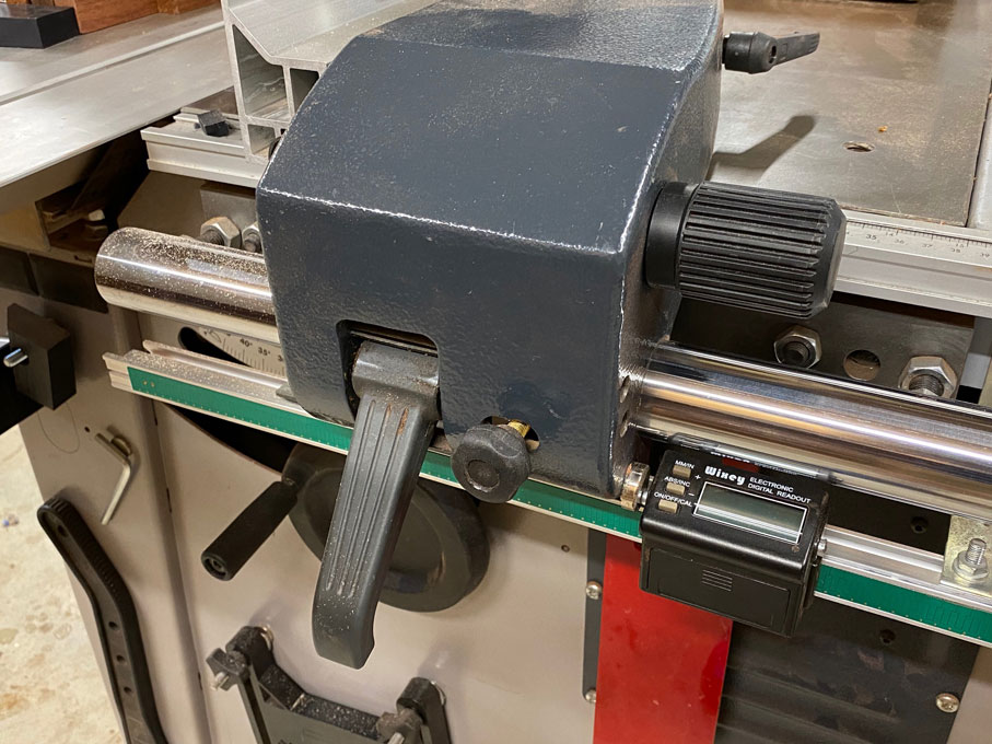
... the N4400 ...

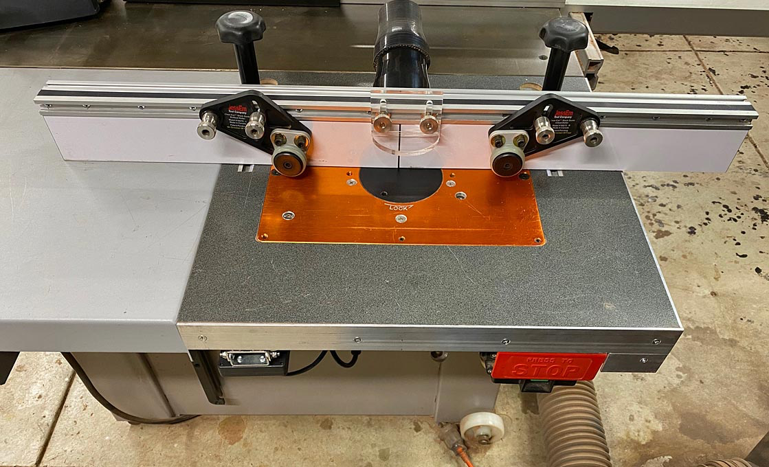
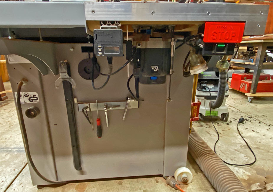
.. and the router table (on the outfeed of the K3) ...
On the left, the DRO flips up ...
With regard the K3 crosscut fence, I have not installed a DRO. Instead, first there is a zero clearance ...
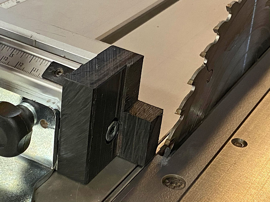

... and then I added a micro-adjuster. I find this more helpful in creeping up on the desired measurement (in micro units) ...

There are articles for all these on my website: http://www.inthewoodshop.com/Powered...ery/index.html
I would be happy to add your design and method as an article, if your are interested. More choices for all.
Regards from Perth
DerekVisit www.inthewoodshop.com for tutorials on constructing handtools, handtool reviews, and my trials and tribulations with furniture builds.
-
21st November 2021, 08:04 PM #5
GOLD MEMBER
- Join Date
- Nov 2018
- Location
- Newcastle
- Posts
- 1,016
Derek, you're welcome to add the iGaging builds to your website.
I think it'd be tricky adding a wixey to the crosscut fence. The EZ Pro I've used doesn't use any cables - it reads the encoder strip directly, like the wixey. Difference is the encoder strip is a thin, flexible band, so it's easy to place on the crosscut fence. It would work on the main fence too, but it would have to go into the slot that the stock scale lives in, so would need some padding to bring it up to the right height for the reader. I only had one of these so it went onto the crosscut fence, and the EZ-DRO I already have will go onto the main fence.
I think I can fit the EZ-DRO's to the K3 and bandsaw main fences without needing to add an additional rail below the fence. If my eyes are straight, it'll need two screws, a magnet, and a bracket to link the fence and encoder reader. The displays have a magnetic back, so they'll just attach to the fence without any brackets. We'll see...
I've read varying accounts of iGaging DRO reliability, so it'll be interesting to see what happens over time (although none of my other iGaging electronics have ever given me any issues)
-
22nd November 2021, 11:05 AM #6
GOLD MEMBER
- Join Date
- Jun 2005
- Location
- Helensburgh
- Posts
- 7,696
I have been looking at this problem for a few years and could not come up with a nice solution unless I found a reading strip that fitted in the top of the extrusion. They are available but the price is not nice so I have held off investigating the problem any further. Like Bernard I have Igaging DRO's but there is so many bits and pieces in the way it is impossible to fit one without major modifications to the fence assembly. I have recently been looking at modifying the blocks that clamp the fence to reduce their height and am about to 3D print some to see if it is a practical idea but I might have another think about that.
I have two CC fences as I bought my saw with no outrigger and later bought the one so I would like to put a DRO on both for parallel cutting. I have also been playing around with 20 series extrusion to use a positioner that can be removed from the saw very quickly as Sam Blasko uses. I have built a support in 20 series at the operator end of the table for large sheets which tend to tip unless clamped and it clamps to the side slot on the table.CHRIS
-
22nd November 2021, 11:13 AM #7
GOLD MEMBER
- Join Date
- Jun 2005
- Location
- Helensburgh
- Posts
- 7,696
They tend to drift at zero and and if I remember M&J a member here said they were noisy electronically. Search for his router table build and he explains it there IIRC. When I finally get around to it I am going to finish the power lift for my A3 based on his RT build electronics. I have mounted the stepper motor and had the thing working and the smoke escaped from the wires due to my poor electronic knowledge. Originally Posted by Bernmc
 CHRIS
CHRIS
-
22nd November 2021, 11:31 AM #8
GOLD MEMBER
- Join Date
- Jun 2005
- Location
- Helensburgh
- Posts
- 7,696
They also can supply a 5mm kerf flat top blade as well. I have all three and the fence needs calibrating every time of course and the Wixey is a pain to zero at times, other DRO's are measure and set to the dimension the fence is currently at. A dado set needs another setting if you need or use a DRO with it. I have often wondered if M&J's electronics with memory could overcome this issue but I have yet to ask him.
CHRIS
-
28th November 2021, 03:25 PM #9
GOLD MEMBER
- Join Date
- Nov 2018
- Location
- Newcastle
- Posts
- 1,016
Sorted out the main fence DRO this weekend.
It took a bit longer than expected as I ended up messing with the saw first. I bought it 2nd hand, and it came with a huge 156cm fence and extension tables to match. It's just too big for my little workshop, so I finally decided to remove one of the extensions, and cut the fence down to around 100cm. That meant I had to go through all the setup and calibration for the tables and fence to get it all square and within tolerances again before I could play with DROs.
I wanted to try to avoid adding aluminium bars or messing with the fence mounting bolts again (and then have to go through the tedious calibration again!). There's a gap between the moving bits of the fence and the table, and I figured there'd be just enough room to get the DRO in there, and mount it directly to the table.
The mounting hardware on the iGaging setup is designed to screw into the back of the encoder -
DRO rear bracket.jpg DRO rear bracket front view copy.jpg
I tried this, but the plate + screws and the supplied encoder brackets held the bits too far away from the table, and they fouled against the micro adjust of the fence. There's only a millimetre or two clearance to play with before adding the mounting hardware on the reader.
So my original plan was to use the supplied hardware, and mount directly to the table with a bit of drilling and tapping. I needed to make custom brackets if I wanted to do this. The other problem was that the fence pokes out of the side of the Hammer to give you the full travel of the fence (see the pics below), so if I stuck to mounting to the table, I'd lose about 120mm of travel, and have to shorten the encoder rail. In practice this probably wouldn't matter as I cut anything that big with the tracksaw, but I thought I'd try plan B and mount the encoder to the fence rail itself.
My K3 has the round aluminium extrusion fence rail, so I could make brackets that slotted into one of the channels.
I printed a few iterations and prototypes as I toyed with different options: The final-ish version is at the bottom of the pic:
bracket prototypes.jpg
They slot into the rail, and are locked with an M4 screw. At the moment, the encoder rail is just press-fit into the bracket, but I'll re-print them with a hole for an M5 grub screw to lock it up.
DRO bracket mounted.jpg
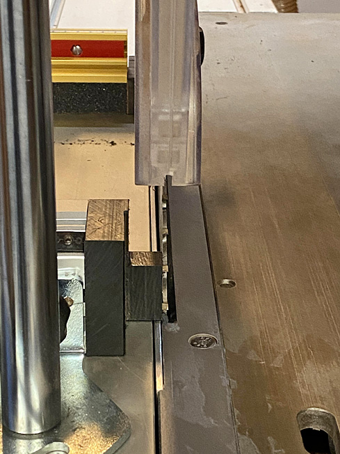
Other side - you can see how the encoder rail runs between the fence and the table:
DRO left bracket mounted.jpg
For testing, I've just stuck a magnet to the reader with some double-sided tape. I'll superglue this when I'm sure it's all where I want it.
DRO magnet reader.jpg
The DRO display is magnetic too, so it'll stick anywhere you want it to on the metal bits of the saw, or there's a holder on the end of a rod supplied with the kit (more for mills and lathes, I think).
So, new leaner saw, with a DRO on both the crosscut and main fences:
Full Saw DRO fitted .jpg
I did a quick and dirty zero against the blade and cut:
DRO accuracy.jpg
You can adjust the calibration/zero and re-check, but I won't bother until I've locked everything in place, and glued the magnet to the carrier - I figure there's enough flex in the system at the moment to give that 0.2mm error.
So, to do:
-Shorten cable - I'll upgrade this to a proper shielded and grounded cable, and possibly solder instead of using the USB connectors. I've got a couple of VFD's in the shop so there's potentially a lot of interference.
- Add locking screws for the encoder rail to the brackets, and reprint. Or make them out of loominum...
Then I may start playing with an android-based custom DRO display (Like Yuriy's TouchDRO project), rather than having to deal with these stupid press and hold button combination xyz while standing on one leg and facing south while whistling 'God Save The Queen' cheap DRO displays.
I'd like to get an electronic readout for the angle of the sawblade too, but currently struggling to find a suitable angle encoder. Watch this space.
-
28th November 2021, 07:22 PM #10
GOLD MEMBER
- Join Date
- Jun 2005
- Location
- Helensburgh
- Posts
- 7,696
Bernard, I see you removed the original measuring tape extrusion entirely.
Edit: I see the difference between mine and yours, there are two type of fences and bar, my original measure for the fence is attached to the tables on an extrusion. Your encoder scale sits where the separate measuring extrusion is on mine.
K3 Felder Pics 005.jpgCHRIS
-
28th November 2021, 07:31 PM #11
GOLD MEMBER
- Join Date
- Nov 2018
- Location
- Newcastle
- Posts
- 1,016
My version of the fence doesn't have a separate extrusion for the scale, Chris - the tape sits in a slot on the round fence rail - you can just make it out in the top slot in this pic:
DRO left bracket mounted.jpg
-
28th November 2021, 07:39 PM #12
GOLD MEMBER
- Join Date
- Jun 2005
- Location
- Helensburgh
- Posts
- 7,696
I could machine the bar but I will think about that as I just spent about three hours calibrating it after it was pulled off for a clean and polish.
CHRIS
-
28th November 2021, 07:59 PM #13
GOLD MEMBER
- Join Date
- Nov 2018
- Location
- Newcastle
- Posts
- 1,016
Yeah, it's a real pain in the posterior! I did it, then decided to shorten the bar, so took it off and then had to do it all over again :/
-
30th November 2021, 06:25 AM #14
GOLD MEMBER
- Join Date
- Nov 2018
- Location
- Newcastle
- Posts
- 1,016
There's a third version of the fence too - a rectangular affair, which I think comes/came with the basic version of the saw. Originally Posted by Chris Parks
The locking mechanism and micro-adjust on mine are different too...
-
1st December 2021, 07:11 AM #15
GOLD MEMBER
- Join Date
- Nov 2018
- Location
- Newcastle
- Posts
- 1,016
New version of the mounts printed and installed. Added a screw to lock the encoder strip, and enlarged the insert that sits in the extrusion, so it's more stable/solid.
new mount.jpg new mount installed.jpg

 Reply With Quote
Similar Threads
-
This weekend's main project
By Michael G in forum METALWORK FORUMReplies: 10Last Post: 21st August 2012, 08:00 AM -
Picket fences
By jamie34 in forum TIMBERReplies: 2Last Post: 13th October 2009, 10:21 PM -
Fences.
By RETIRED in forum BANDSAWSReplies: 25Last Post: 10th August 2007, 08:18 PM
