

 Thanks: 0
 Likes: 0
 Needs Pictures: 0
 Picture(s) thanks: 0
Results 1 to 15 of 19
-
15th August 2015, 04:43 PM #1
 Senior Member


- Join Date
- Dec 2013
- Location
- Sydney
- Posts
- 139
 Tanner tilting table saw question
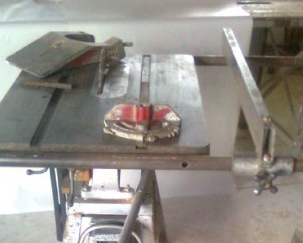
One of the projects I've got going at the moment is getting this 1950 Tanner tilting table saw running. The machine is in pretty good condition and hasn't seen much use so I'm not stripping it right down and painting it, just giving it a good clean. It's got a nice mitre gauge which I will re-paint and give the engraved scale a polish.
However, the rip fence is missing a key part. The fence runs on a round steel tube bolted to the front of the table, but I don't have the locking mechanism and I'm not exactly sure how the lock would have worked. There's a casting that wraps around the tube, and a hole through the casting perpendicular to the tube and offset to the bottom of the tube. I'm thinking there would have been some sort of either wedged end on a bolt with a knob at the front that drew it forward to lock against the round tube, or maybe a cam shape on the end of a shaft that got twisted by a lever to lock against the tube.
Does anyone have any idea what the locking mechanism would have looked like, or can anyone point me to how other fences running on round tubes achieve the locking action?
Thanks in advance,
Graham.
IMG_6021.jpgIMG_6022.jpgIMG_6016.jpgIMG_6019.jpg
-
15th August 2015 04:43 PM # ADSGoogle Adsense Advertisement
- Join Date
- Always
- Location
- Advertising world
- Posts
- Many
-
15th August 2015, 04:52 PM #2
Senior Member
- Join Date
- Dec 2013
- Location
- Sydney
- Posts
- 139
And another question:
The rip fence is a rectangular steel tube, and has an L shaped bolt at the far end with a knurled knob that looks like it's a lock for the far end of the fence. There are two holes in the back edge of the table for a runner, but there was no runner with the saw. I'm assuming there would have been some sort of rectangular bar or maybe an angle running along the rear of the table and this L shaped part gripped onto it to lock?
Can anyone suggest what this runner would have looked like?
Thanks,
Graham.
IMG_6020.jpg
-
17th August 2015, 12:34 AM #3
SENIOR MEMBER
- Join Date
- Oct 2009
- Location
- South Africa
- Posts
- 950
That rip fence looks a lot like the one in my old Delta bandsaw (which dates from the '30s). I'll be able to post a picture of it when I get home later. It may not be exactly the same fence you have but it might help. Originally Posted by Oldbikerider

-
17th August 2015, 04:50 PM #4
GOLD MEMBER
- Join Date
- Oct 2007
- Location
- Alexandra Vic
- Age
- 69
- Posts
- 2,810
The fence lock might have one of two configurations, but looking at the underneath shot I suspect the first might be what was used.
Consider a length of round bar of a diameter similar to but slightly smaller than the internal diameter of the semi circular recess in the casting shown on pic 4. The bar stands vertical when situated in the clamp. At the top, it is machined to have a radius equal to the guide bar cut lengthwise along the bar, and below that, it has a hole drilled and threaded perpendicular to the axis of the bar, with a threaded bar inserted, and passing through the front of the casting, where it mates with a clamping handwheel or lever. When the handwheel or lever are in the clamped position, the funny shaped piece of bar is pulled up to the guide bar and clamps the casting and hence the fence, when in the released position, it is clear of the guide bare and the fence is free to move. There may be a release spring on the threaded bar to push the clamp bar off the guide bar. Can draw later if you need.
Second option would be an eccentric working as a cam on the clamping spindle, but I think the first option more likely.I used to be an engineer, I'm not an engineer any more, but on the really good days I can remember when I was.
-
17th August 2015, 05:41 PM #5
Senior Member
- Join Date
- Dec 2013
- Location
- Sydney
- Posts
- 139
Colin and malb,
Thanks very much for the suggestions. Colin, a photo would be great, thanks.
Malb, I'm not quite getting what you are describing, but a sketch would help. That hole through the clamp body casting, and the semi circular shape in the casting under the guide rail, both have a horizontal axis, so I'm not quite understanding your comment about the clamp bar standing vertical. The guide rail is attached to the front of the table with two spacers with bolts through, so any vertical clamp on the rear of the guide rail would foul those two spacers as the fence is slid sideways. I'll take a couple more pictures tonight to clarify what I'm saying.
Graham.
-
17th August 2015, 08:06 PM #6
Senior Member
- Join Date
- Dec 2013
- Location
- Sydney
- Posts
- 139
Here's a couple of shots of the clamp body casting, mounted on the guide rail as it would be oriented on the saw. One of the bolts that goes through the spacers to mount the rail on the front of the table is visible, and you can see that any clamp part that wraps around the back of the rail would foul on these bolts.
I'm really thinking that the lock mechanism must have been some sort of cam or taper that got pulled or twisted by a knob or lever mounted on the front of the clamp body. But happy to take any other suggestions.
Thanks,
Graham.
IMG_6033.jpgIMG_6034.jpg
-
17th August 2015, 11:09 PM #7
 GOLD MEMBER
- Join Date
- Sep 2008
- Location
- Petone, NZ
- Age
- 68
- Posts
- 2,823
Tanner were still in existence a few years ago, and may still be trading. You could contact them for parts and/or advice.
Cheers, Vann.Gatherer of rustyplanestools...
Proud member of the Wadkin Blockhead Club .
.
-
17th August 2015, 11:39 PM #8
GOLD MEMBER
- Join Date
- Oct 2007
- Location
- Alexandra Vic
- Age
- 69
- Posts
- 2,810
Graham, I got my directions confused in my initial description because I thought the open section of the casting was facing the floor rather than the table.
The second set of photos have clarified the situation and I have a better idea of the configuration, which works on the same principal, but different orientation. I now think that the clamping was achieved with a threaded handwheel, and discount the possibility of a lever clamp actuation.
Both of the second set of photos show that pieces of the casting around the semicircular recess have been broken off. The missing parts would have been used to stop the clamp rotating as the handwheel was tightened or loosened to clamp or release the guide bar. They have probably been broken off as a result of the handwheel seizing on it's threaded shaft at some time, and excessive force being used to attempt to release it, resulting in the clamping block rotating and cracking the casting and allowing the small locating extensions to break off.
Basically a threaded bar passes through the small hole visible in the first set of photos, terminating in a handwheel on the face side, and a block of some sort on the table side. The block has a face shaped to closely match the curvature of the guide rail, and possibly a fairly light spring is mounted over the threaded bar between the block and the inside face of the casting, to push the block away from the guide rail as the handwheel is released. As the handwheel is tightened, it draws the curved face of the block into tight contact with the guide rail which pulls the casting into contact with the guide bar, effectively locking the casting and curved block to the guide rail.
I am absolutely shot at the moment, but will try to sketch the system tomorrow night from a different computer as I don't have CAD software on this one.I used to be an engineer, I'm not an engineer any more, but on the really good days I can remember when I was.
-
17th August 2015, 11:59 PM #9
SENIOR MEMBER
- Join Date
- Nov 2011
- Location
- Newcastle NSW
- Posts
- 775
Is this the same fence?
if so then it's twisting handle, not cam arrangement, and the handle threads on. If I was to take a guess, I am imagining a bolt type arrangement with a round head matching the diameter of the curve on the casting at the back (assuming that is bigger than the hole in the front). Where the bolt head meets the guide rail, it is machined to mate with the curve of the bar, so it clamps the fence to the rail.
Hope that makes sense.
cheers,
Camo
EDIT: Slow typing and stopping for a coffee results in people posting while your writing, so see below as well
-
19th August 2015, 03:23 PM #10
Senior Member
- Join Date
- Dec 2013
- Location
- Sydney
- Posts
- 139
Brilliant guys, I think I've got it worked out now. One clue was that photo, thanks Camo, showing the knob, and the other was malb's description.
Last night, I made up a trial part using a 1/2 inch bolt, fitted with the thread end protruding through the front of the casting and with half it's thickness scalloped out to match the diameter of the rail tube. Tightening a nut on the front of the bolt nicely clamps the fence in place. The only issue is that whilst clamped tightly enough, the casting does still rock side to side, so I'll need to do a bit of judicious filing to some of the machined surfaces that slide on the rail. I'll make up a final version, make or buy a suitable hand wheel, then post photos of the end result.
Camo, where did you find that photo? Were there any more of the saw? It seems to be identical to mine.
Thanks everyone for your help,
Graham.
-
19th August 2015, 07:43 PM #11
SENIOR MEMBER
- Join Date
- Nov 2011
- Location
- Newcastle NSW
- Posts
- 775
Graham, Originally Posted by Oldbikerider
Just a google search, and switched to images (once I got past all the full house images ), can't remember what terms I used now (that was the only image, I think it was from a closed sale).
Glad you have a plan. Just one thing with the design I was thinking, you want to make sure you don't scar the back of the rail with the bolt. If you find that may happen, then perhaps you can modify it so it goes through a brass piece (brass is often used below a bolt that makes contact with a steel shaft, the brass is strong enough to bind, but soft enough not to scratch the steel.
Food for thought.
Cheers,
Camo
-
25th August 2015, 04:28 PM #12
Senior Member
- Join Date
- Dec 2013
- Location
- Sydney
- Posts
- 139
Just an update on the Tanner saw fence lock.
Since I last posted, with the help of a friend from Aukland, I have confirmed from NZ company records that Tanner went out of business in 1997.
But, Tanner apparently sold their stock of spare parts to this company in NZ: http://www.powertoolcentres.co.nz/st...ols-whangarei/ Ask to speak to Roger - he seems to be the expert on the old Tanner tools - he recognised my 65 year old saw and immediately knew what parts I was after.
To quote from their website "We are Sole Agents for Tanner Tools and still maintain a range of spare parts for their various machines."
I just ordered a star wheel and the lock bolt in question for a very moderate sum, and postage to Sydney was only $10.00.
I'm posting this here to help anyone else that may need spare parts for old Tanner machines.
Graham.
-
25th August 2015, 06:25 PM #13
SENIOR MEMBER
- Join Date
- Nov 2011
- Location
- Newcastle NSW
- Posts
- 775
Graham, Originally Posted by Oldbikerider
Great detective work to source the parts and thanks for sharing. I am curious now to see what the part looked like, any chance of a picture when it arrives, I don't need to know, I just want to know
Cheers,
Camo
-
18th September 2015, 01:51 PM #14
Senior Member
- Join Date
- Dec 2013
- Location
- Sydney
- Posts
- 139
Update on the Tanner fence clamp
This is the part I made up to lock the fence clamp following suggestions here. It's been doing fine service on the machine for the past few weeks...
IMG_6160.jpg
-
18th September 2015, 02:01 PM #15
Senior Member
- Join Date
- Dec 2013
- Location
- Sydney
- Posts
- 139
And this is what just arrived in the mail from New Zealand. It looks brand new with no wear or rub marks, so I guess it's been in a spare parts bin for the last 65 years. The red star wheel is branded Tanner but must be for a much later machine, and does not match the cast metal knob in the picture that Camo posted earlier. It works OK here, but I'll look at sourcing something that looks a bit more original.
So the fence locks well, and I'm very happy to have found an original spare part. Now I'm encouraged to strip the whole machine down to bare metal and give it a full restoration...... we'll see.
Graham.
IMG_6161.jpgIMG_6164.jpg

 Reply With Quote


Similar Threads
-
Tanner 10" Table Saw
By johnmd in forum TABLE SAWS & COMBINATIONSReplies: 11Last Post: 15th June 2023, 11:41 AM -
Wolfenden 10inch Tilting Table saw.
By L.S.Barker1970 in forum ANTIQUE AND COLLECTABLE TOOLSReplies: 18Last Post: 13th August 2021, 01:17 PM -
Tanner 10" DE-LUXE TILT ARBOR table saw
By freebs in forum TABLE SAWS & COMBINATIONSReplies: 0Last Post: 8th February 2015, 09:49 PM -
Left or Right Tilting Table Saws
By bjn in forum WOODWORK - GENERALReplies: 2Last Post: 15th November 2004, 09:11 PM
