

 Thanks:
  Likes:
  Needs Pictures:
  Picture(s) thanks:
Results 61 to 75 of 300
-
8th September 2009, 06:44 AM #61
 Senior Member


- Join Date
- Jul 2009
- Location
- Netherlands
- Age
- 67
- Posts
- 248
 Hi Simon,
 Originally Posted by SimonLew

I just started building GIS and had similar "issue" with an available 2HP shortshaft Yamaha. Inspired by Sisu's picture I have made this transom including a "sculling" notch on the other side to give it a more symetrical look.
It should work with rudder when sailing. Outboard can be lifted out of the water, but not turned around completely ( it does not have a reverse )
For me this looks quite okay ..... and now GIS can be used as motorsailer
-
8th September 2009 06:44 AM # ADSGoogle Adsense Advertisement
- Join Date
- Always
- Location
- Advertising world
- Age
- 2010
- Posts
- Many
-
8th September 2009, 07:34 AM #62
Senior Member
- Join Date
- Jul 2008
- Location
- Florida USA
- Posts
- 337
Hi Ralph,
I like your thinking on the transom cutouts and the sculling notch is pretty cool. I am inclined to also do an outboard notch. My two choices of outboard are a 2hp Suzuki or a 5hp Tohatsu. Both short shaft. The Tohatsu has reverse gear but is much heavier than the Suzuki so I would prefer to use the Suzuki especially when, on longer outings, I might want to stow the Suzuki amidships and only use it if the wind dies and I have to be back at work on Monday
BTW, I'm closely following your boom development efforts. It's really good stuff! I have a fair bit of sailing experience but am completely clueless about traditional rigs like the balanced lug. So you are providing a great education. Simon
Simon
My building and messing about blog:
http://planingaround.blogspot.com/
The folks I sail with:
West Coast Trailer Sailing Squadron
-
8th September 2009, 10:40 AM #63
Happily receives emails.
- Join Date
- Jul 2005
- Location
- 'Delaide, Australia
- Age
- 65
- Posts
- 8,138
I do know of one or two boats that have used outboards without the notches. So check your outboard first.
MIK
-
8th September 2009, 12:36 PM #64
Senior Member
- Join Date
- Jul 2008
- Location
- Florida USA
- Posts
- 337
That's good advice MIK. I'm looking for once in a while auxiliary power (if at all) and don't really care if it's set up optimally for the outboard. So maybe one of my outboards will be just long enough to work. Will fit it all up before hacking into the transom.
Simon
My building and messing about blog:
http://planingaround.blogspot.com/
The folks I sail with:
West Coast Trailer Sailing Squadron
-
9th September 2009, 03:32 AM #65
Senior Member
- Join Date
- Jul 2009
- Location
- Netherlands
- Age
- 67
- Posts
- 248
Most short shaft outboards have their anti-cavitation-plate ( horizontal plate just above propellor ) in the 40 cm ( 16 inch ) range below their transom height. Normally this plate should be just below or up to 1 inch under boats bottum level for optimum results ( low drag versus cavitation )
Long shaft's have this in 50 cm ( 20 inch ) range. This is very "general", ofcourse there will be exeptions.... so you indeed need to check yourself.
In practice this means long shafts could be fixed at max 50cm transom height and short shafts at max 40 cm. This means you really need a notch in GIS to get an avarage shortshaft fixed. Longshafts will fit great on the standard transom and probably most electric drives too...I would probably prefer these options new.
While I do have a shortshaft available, I did not want to spend money on a longshaft. I made my notch at 39 cm above bottum of the transom in a straight line. Including heeling angle of this transom it will be around 38 cm sufficient to keep this anti-cavitation-plate under water in most circumstances.
And indeed.......I don't think I will use it a lot while GIS has generous sail and seems to row pretty well too. But just in case.....I probably hate myself not to have made this
possibility ........and making it afterwords is a pain.
-
16th September 2009, 01:04 PM #66
Senior Member
- Join Date
- Jul 2008
- Location
- Florida USA
- Posts
- 337
Bird's Mouth Mast
Made a good bit of progress on the mast. I am making it out of Home Depot douglas fir 1x2x10s and it's coming along nicely. There is more detail on my blog but here are the highlights.
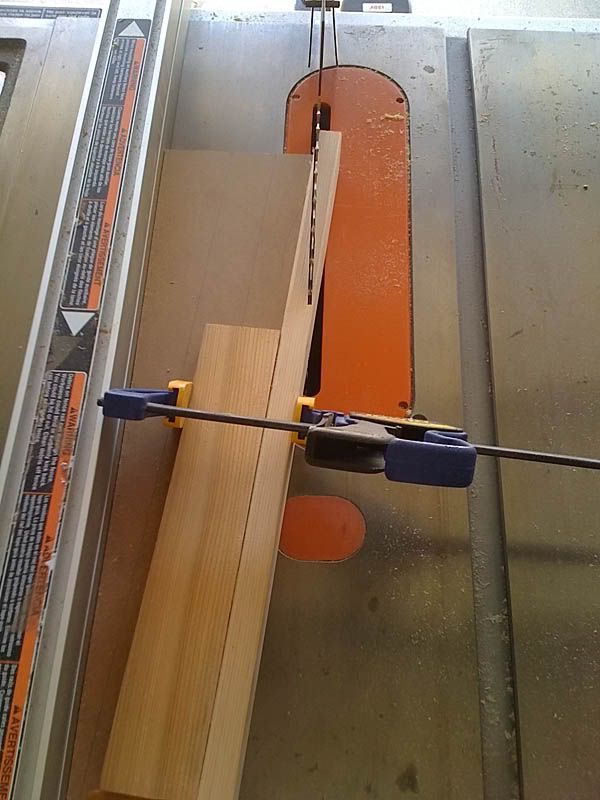
I had to run a few test strips on the table saw to set up for the bird's mouth cut. My wife wants it for a pencil holder
I built a 10:1 taper jig for the stave scarfs
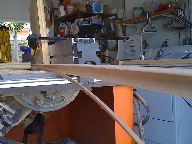
After the scarfs were epoxied together I ripped the staves to the final dimensions on the table saw. Then set the table saw blade at 45 degrees and tweaked the depth of cut and fence location to get it just right, and ran the staves through.
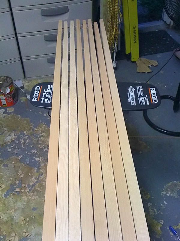
I made a 1/4" ply template for the stave taper and used it to draw a pencil line on each stave. Then band sawed and planed the edge opposite the bird's mouth cut of each stave. The finished staves look like this.
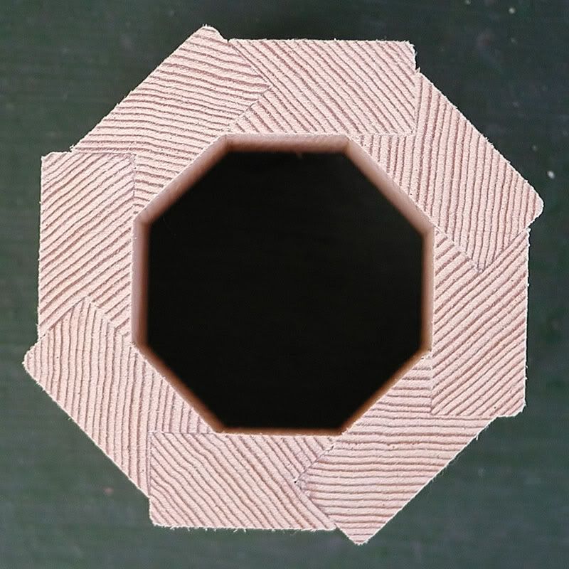
Test fit of the staves went well and the taper looks right. The mast weighs 19.5lbs (8.9kg) at this stage.
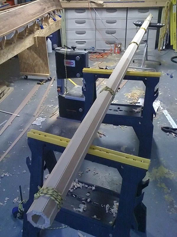
Now, how does one glue this up so that it's straight? The taper on both ends makes this a challenge. Any suggestions?Last edited by SimonLew; 17th September 2009 at 01:31 AM. Reason: Fixed disappearing photos, again
Simon
My building and messing about blog:
http://planingaround.blogspot.com/
The folks I sail with:
West Coast Trailer Sailing Squadron
-
16th September 2009, 01:11 PM #67
SENIOR MEMBER
- Join Date
- Jul 2008
- Location
- Fenwick, Michigan
- Age
- 75
- Posts
- 908
Excellent progress!
Great pics, too!
Thanks.
Bob
-
17th September 2009, 05:48 AM #68
Happily receives emails.
- Join Date
- Jul 2005
- Location
- 'Delaide, Australia
- Age
- 65
- Posts
- 8,138
Do a dry run Simon.
I suspect/hope that if the untapered part is clamped up first then the rest will tend to be self aligning.
Or close enough. Remember that even solid masts often have a bit of asymmetry.
Do a dry run and see if it's so.
The method they used at duck flat is to put the brown packaging tape in two of the joins so the mast can be split after gluing to coat the inside and fit the plugs and the partner reinforcement.
They use a few hose clamps but do wraps around with tightly pulled brown packaging tape to do most of the clamping.
This is really cool to see. I might copy some of these posts over to a devoted birdsmouth mast thread once it is complete. Thanks hugely for sharing.
I think Clint (USA NE) and duckflat (OZ). can make up staves with the birdsmouth cuts and even the tapering for those who don't have the gear. David Graybeal has a woodworking shop too in Oregon.
Best wishes
MIK
-
17th September 2009, 07:24 AM #69
Senior Member
- Join Date
- Jul 2008
- Location
- Florida USA
- Posts
- 337
How should I plug the mast base? I have seen mast base plugs which go from the base up past the partner. Is that necessary or can I just use a thick octagon or disk bedded in thickened epoxy at the base and another one at partner level to take the crushing loads?
Definitely doing some dry runs. I have played around with the clamping and I get some droop from where the mast begins the taper to the tip. It's not a huge amount and can be eyeballed straightish so maybe fine. It's tough to get a 16' long straight surface as a reference and I don't want to build a strong-back for just one mast. I'll document whatever riggery I come up with
MIK, you are welcome to use any of my photos/posts from here or the blog.Simon
My building and messing about blog:
http://planingaround.blogspot.com/
The folks I sail with:
West Coast Trailer Sailing Squadron
-
17th September 2009, 05:17 PM #70
i-Sails Australia
- Join Date
- Apr 2009
- Location
- Hunter Valley NSW
- Age
- 69
- Posts
- 1,759
Simon, I agree with MIK about the tape. Perhaps 3 steel band clamps (top, middle and bottom) and then just the brown packaging tape. I've often used just the tape for a lot of antique furniture and cricket bat repairs, and you can achieve amazing pressure with it. Unlike the clear packaging tape, the brown stuff has just the right amount of stretch to create the pressure before it snaps. Originally Posted by Boatmik
Love your work!
-
18th September 2009, 12:03 AM #71
SENIOR MEMBER
- Join Date
- Sep 2007
- Location
- Savannah GA USA
- Posts
- 583
I bought a roll of 2" wide shrink wrap which is marketed as "flat twine." It comes on a 900 foot roll with a handle and would seem to be ideal for clamping up a mast. I'll be using it on the laminated chines of my Simmons Sea Skiff. The advantage I see over packaging tape is its stretchability and the fact that it sticks to itself but nothing else.
As for keeping your mast straight while the glue sets up I would see if gravity would bring it straight if blocked up carefully. Put as many supports as needed at the straight section then position the bent section at the top in such a way that the weight of the assembly tends to pull it straight. Once you find the correct position mark everything so it can go right back after glue-up. If gravity isn't enough you could add a little weight where needed.The "Cosmos Mariner,"My Goat Island Skiff
http://s176.photobucket.com/albums/w168/MiddleAgesMan/
Starting the Simmons Sea Skiff 18
http://www.flickr.com/photos/37973275@N03/
-
18th September 2009, 02:36 AM #72
Senior Member
- Join Date
- Jul 2008
- Location
- Florida USA
- Posts
- 337
Thanks for the tips guys. However I end up doing this its going to get interesting.
The weather is starting to cool off just a bit so that will help with epoxy working time. My least favorite part of this is the time pressure. It will take a few minutes to butter up all of the staves then a few more to assemble then a few more to jig up straight and before you know it the epoxy is going off I'm definitely going to use MIK's suggestion of brown taping two opposite joints so that the mast will come apart in two halves for installation of internal plugs.
Speaking of plugs any recommendations for the mast base? Should there be one long plug from base to slightly above the partner or separate base and partner plugs?Simon
My building and messing about blog:
http://planingaround.blogspot.com/
The folks I sail with:
West Coast Trailer Sailing Squadron
-
18th September 2009, 05:09 AM #73
Happily receives emails.
- Join Date
- Jul 2005
- Location
- 'Delaide, Australia
- Age
- 65
- Posts
- 8,138
Howdy.
Plug in bottom can be relatively thin .. maybe 25mm.
One at top needs to be thick enough to take the halyard fitting fastenings , so might be around 60mm.
At the Partner - I am always tossing between using something quite thin - maybe 19mm stock sjut to prevent crushing or whether to make it about 300mm long but cut the ends off so that they are heavily angled - leaving about 50mm that is not angled in the middle.
Everything can be loosely fitted and the joins filled with lots of epoxy.
Michael
-
18th September 2009, 05:53 AM #74
Senior Member
- Join Date
- Jul 2006
- Location
- Portland, Oregon, USA
- Posts
- 334
I'd vote for the latter. Originally Posted by Boatmik
Though - what I've done in the past is to bandsaw a pair of long V's into each end of the plug... at 90 degrees to each other (on 8-sided sticks). That leaves you four long, tapered prongs at each end. It's probably overkill in terms of minimizing stress risers, but it's quite easy to do on a bandsaw.
Cheers,
-
18th September 2009, 07:43 AM #75
Happily receives emails.
- Join Date
- Jul 2005
- Location
- 'Delaide, Australia
- Age
- 65
- Posts
- 8,138
David in his office just drew my attention to the fact that I had not answered his post above.
The post above is the single most amazing thing I have ever read in my life.
I'll say it again.
The most amazing thing I have seen in my life.
(is it OK if I stay another couple of days?)
MIK

 Reply With Quote


Similar Threads
-
first build
By joem in forum MUSICAL INSTRUMENTSReplies: 2Last Post: 14th October 2007, 02:53 PM -
Simon Seaskiff revisited
By Marc in forum BOAT BUILDING / REPAIRINGReplies: 9Last Post: 9th February 2007, 09:13 PM -
Simon and Patrick
By The Hornet in forum MUSICAL INSTRUMENTSReplies: 3Last Post: 7th November 2006, 02:35 AM -
Is there anyone in the NT who could build this? (take 2 sorry)
By leahjace in forum WOODWORK - GENERALReplies: 11Last Post: 24th April 2005, 08:17 AM
