

 Thanks:
  Likes:
  Needs Pictures: 0
 Picture(s) thanks:
Results 196 to 210 of 3347
-
29th March 2009, 08:52 PM #196
 GOLD MEMBER


- Join Date
- Jan 2009
- Location
- Blaxland, Australia
- Age
- 65
- Posts
- 2,551

Howdy MIK,
Um...that's more or less sort of what I did, athough I did a bit of a lot "backing and filling": backing off the screw, letting the panel fall back onto the cleat, then driving the screw back in. This seemed to partially solve the problem I was getting with daylight appearing between panel and cleat. The other part of the solution was to drive in the extra screws until the ooze appeared. But you're right, I did use too many! I probably used less on the sheer clamps, although the the timber was springier: I was getting used to the process by then. At this point I'm almost feeling as though I've been to a boat-building school - but without the 8-hour/day structure...
Once again, I'm glad that I started on the PDRacer and not the Goat - it would have been rather heartbreaking to have had some of the Duck problems that I had with what is - to my mind - and somewhat "worthier" boat. This is said in the context of a large amount of work invested in the Duck - had it been the other way around, I may have been saying the same thing but in reverse.
Anyway, I'll be a lot more parsimonious with the screws when I attach the "big bendy things" to the "small bendy things" (the big bendy things are going to be a lot bendier that the small bendy things ;).
I've just been doing some chinelog trimming and CB sanding for test fitting, but am up for the evening now. I'll leave the sheer clamp screws in overnight.
Thanks also for your kind words :))))).
Cheers,
Alex.
-
29th March 2009 08:52 PM # ADSGoogle Adsense Advertisement
- Join Date
- Always
- Location
- Advertising world
- Age
- 2010
- Posts
- Many
-
29th March 2009, 10:02 PM #197
GOLD MEMBER
- Join Date
- Jan 2009
- Location
- Blaxland, Australia
- Age
- 65
- Posts
- 2,551
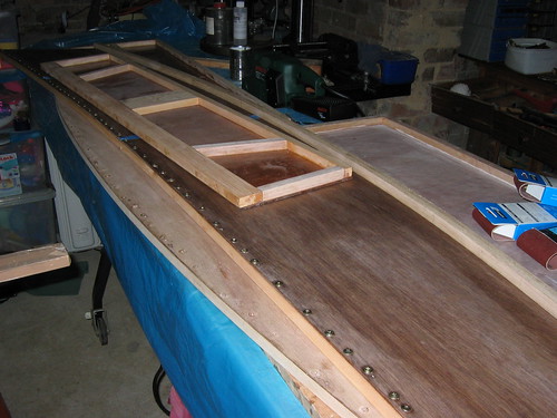
So, what I done today? The sheer clamps, as mentioned above :). Like my engineering projects, much time is spent setting up, but unlike the engineering, also much time cleaning up! In fact, the actual screwing on of the clamps was relatively quick and not quite as messy as I was fearing, although it was just as well I had all that tape everywhere!
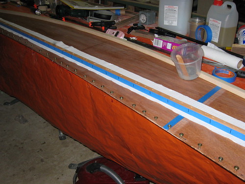
Apropos MIK's comment on the number of screws and my assertion that I didn't use as many on the sheer clamps: I got that one wrong! See photos below. The initial number of screws was at a spacing of around 150 mm, but I added more when I found that I got a closer, flatter interface between the panels and the clamps by doing so.
Anyway, 'tis done now, and the holes will get filled up with a resin and BoteCote light-weight filler mixture, so the weight penalty won't be too bad (the wood is still there of course, just compressed).
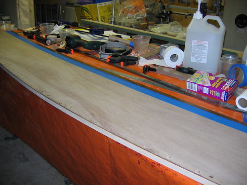
1. Off we go again: resin strip added for the sheer clamp on the starboard side panel - brushed on sparingly straight out of the tub this time: the wood is bare, so the resin is going to soak in to some extent. More is therefore needed...
2. Indicator marks for the screw holes on the tape: because the clamp got repositioned at one point, there are mulitple holes in the clamp. The marks indicate the "real" holes. I'm going along moving the screws from the clamp (where they were stored) to the right holes in the panel. Note that as installed, the marks will not be viible from the working side! At least they were useful to make sure that the screws got into the right holes! This mistake was avoided for the second sheer clamp :).

3. Glueing up. I found a use for the ridgey toilet paper: a convenient mat to place under the sheer clamp while adding the glue.
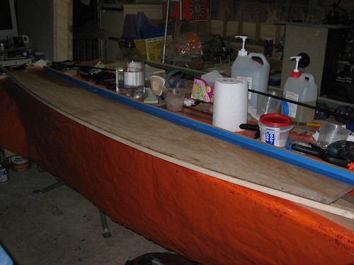
4. Nailed down! Not too much glue spread around on the other sideof the panel! Took a bit of cleaning with the meths and paper towel, even so ;). Once again, apologies for the under-exposeure of the photo - perhaps I need to use a flood lamp (I have one, but it's very hot)...

5. Panel flipped over for cleaning: tape still in postion at this stage
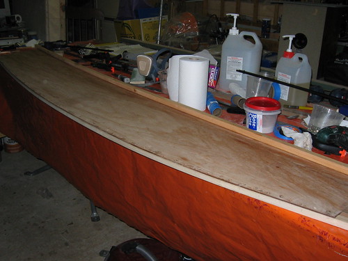
6. Tape removed and the panel cleaned up. I used the back of a real chisel for this one - it needed the stiffness (some parts of the tape had already been happily glued down by the resin!). The chisel was one that I hadn't finished renovating, so didn't have a proper cutting edge. Even so, ithe chisel is going to need some more work done on it now, to get it back on track...
7. Big pile o' boat bits! Two side panels and three bulkhead - all the parts needed to make a 3D structure :). Minus the bottom - the big bendy bit - of course. I've since started nibbling away at the chinelogs and checking the cockpit bulkhead and transoms for fit. I say started: haven't got very far yet!
Next up: well, not quite 3D yet! Lots of small tweaks and stuff. Have to go really carefully here too: one slip, and I'll have an interestingly trapezoidal Duck on my hands!
-
29th March 2009, 10:34 PM #198
GOLD MEMBER
- Join Date
- Jan 2009
- Location
- Blaxland, Australia
- Age
- 65
- Posts
- 2,551
Hmmm...
I've just been reading the more recent posts in the "Solo 'Expedition' Boat" thread of Brian's, specifically the interchange on join strength.
Query to MIK: given that I've gone and perforated the chinelog and sheer joints quite significantly, should I atcually be filling the holes in with neat epoxy, or the high-strength glue mix, rather than the epoxy/light-weight filler mix? Or am I just not going to get the joint strength back that I would otherwise have had, had the holes been further spaced apart? And should I therefore be putting (double-bias) tape aroun the hull bottom?
Cheers,
Alex.
-
30th March 2009, 08:00 AM #199
Happily receives emails.
- Join Date
- Jul 2005
- Location
- 'Delaide, Australia
- Age
- 65
- Posts
- 8,138
I usually fill holes with the fortifier mix because I don't always have the lightweight filler mix available.
But either is fine.
The fortifier/gluing powder is hellish to sand though so I usually put a neat, small blob of it in and on the hole using the piping bag method. If you use a putty knife it increases the surface area to be sanded and if putty knifed off dead flat some of the resin will be absorbed by the timber leaving a dimple.
MIK
-
30th March 2009, 12:39 PM #200
GOLD MEMBER
- Join Date
- Jan 2009
- Location
- Blaxland, Australia
- Age
- 65
- Posts
- 2,551
OK, MIK, thanks. What about a mixture of fortifier and lightweight?
I got the screws out of both sides without a hitch except for one screw, which needed the drill setting. No sign of cleat movement :).
Cheers,
Alex.
-
30th March 2009, 03:47 PM #201
Happily receives emails.
- Join Date
- Jul 2005
- Location
- 'Delaide, Australia
- Age
- 65
- Posts
- 8,138
No point in a mix .. if you have the light stuff ... use it. Was I trying to say that the whole time???
I even confuse myself sometimes.
MIK
-
30th March 2009, 05:19 PM #202
GOLD MEMBER
- Join Date
- Jan 2009
- Location
- Blaxland, Australia
- Age
- 65
- Posts
- 2,551
Hi MIK,
You probably were saying that - I'm still feeling really dopey :(. Got sent off for a CT scan of my sinuses today, with the doctor giving me an advance warning that I might have to curtail my boat-building activites in the very near fututre :(((((.
I'll use the lightweight filler, and a few drops of Prooftint "maple" to tone down the whiteness (otherwise I'm going to have a polka-dotted interior under the side decks).
Cheers,
Alex.
-
30th March 2009, 05:29 PM #203
GOLD MEMBER
- Join Date
- Jan 2009
- Location
- Blaxland, Australia
- Age
- 65
- Posts
- 2,551
As a result of spending a good deal of the day visiting various medical persons, I have only had time to remove the screws from the side panels. At least I've got all the really difficult stuff apart from the 3D and mast step/partner assemblies done.
I'll be somewhat upset if I'm ordered to stop, though!
-
30th March 2009, 10:22 PM #204
GOLD MEMBER
- Join Date
- Jan 2009
- Location
- Blaxland, Australia
- Age
- 65
- Posts
- 2,551
Did a bit of work after dinner this evening. Fixed up the chinelog ends on the other side panel, and started to sand back the outer cleats on the stern transom, so that they fit snugly onto the side panels. Still working on that when I stopped. Used the Permagrit block here. Photos will reveal all, tomorrow.
Avoided the odd measurement in the diagram in the instructions on page 14 saying to cut the cleats back by 24 mm. Eh? 5 mm of glue? Must have been a typo, or very thick cleats or transom ply ;). Or the measurement was taken from the aft side of the ply?
I've been using the Japanese saw to trim the chinelogs: for me the best things about this type of saw (and their Western cousins, the "Exacto" razor saws) are the ultra-thin kerf, and the relatively sharp, clean cut. I'm still getting used to the "pull" cut, and still not sure if even after a lot of practice that I still won't prefer the push cut. What I was brought up with, I suppose. But the former two attributes are great :).
Hopefully tomorrow won't involve racing around the country side as much, and I can proceed with some more of the cleaning and trimming, and maybe hole-filling.
Another query to MIK: the stern transom drain holes are not marked on the plans, and only appea in the Mk 1 photos. Are they a Mk 1-only feature that you culled in the Mk 2? I can't remember if they appear on pdracer.info, but I dare say I should go and have a squizz. Right now!
Cheers,
Alex.
-
31st March 2009, 08:57 AM #205
Senior Member
- Join Date
- Jul 2006
- Location
- Portland, Oregon, USA
- Posts
- 334
Alex,
Since you're using Japanese pull saws, perhaps you're familiar with the philosophy of wabi-sabi? Very appropriate to boat building and ownership. The three main tenets are: nothing is ever perfect; nothing is ever complete; nothing lasts forever.
-
31st March 2009, 09:03 AM #206
GOLD MEMBER
- Join Date
- Jan 2009
- Location
- Blaxland, Australia
- Age
- 65
- Posts
- 2,551
Dave - I'm familiar with the spirit of wabi-sabi, albeit in slightly different form ;). But being a bear of somewhat limited attention span, being reminded of them (often) is a very worthwhile thing!
Cheers,
Alex.
-
31st March 2009, 09:17 AM #207
GOLD MEMBER
- Join Date
- Jan 2009
- Location
- Blaxland, Australia
- Age
- 65
- Posts
- 2,551
While I happen to be here - just had the "black:Stone" Bosch ROS disks and fence attachement for the belt sander delivered aus mytoolstore.com.au - fantastic service, thanks Rob! I haven't seen these anywhere other than in Bosch literature - Rob managed to source and send them in a day (weekend in the middle). And at a good price, too :).
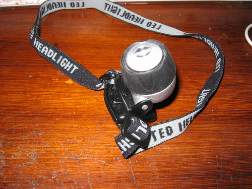
And while I'm going on about one of my weak spots - gadgets - here are a couple of photos of my "miner's lamp" headlight. I should have been using this instead of the multi-eyed torch for scrutinising parts that are in shadow as a result of my lighting "arrangements". It got tucked away in a drawer and forgotten about (see above about weak spots) - at least in the context of boat building - until I needed it the other night when we had the "lights off" hour. The other reason I had overlooked it (well, I know this an excuse) is that I couldn't fit it on my head at the same time as the magnifiers (head's not big enough ;). Apart from reading at night during power blackouts, I use the headlight for when I need to do something to the rat's nest of computer cables lurking under my desk. I got it either from Jaycar or www.mrgadget.com.au (aply named!), can't remember which.
1. Overview of the headlight: light is mounted on a hinged bracket, which allows more precise placement of the beam
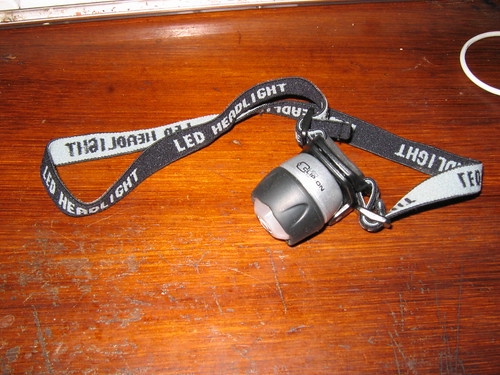
2. Headlight closeup. Moved on its mounting bracket from position in previous photo
-
31st March 2009, 09:36 PM #208
GOLD MEMBER
- Join Date
- Jan 2009
- Location
- Blaxland, Australia
- Age
- 65
- Posts
- 2,551
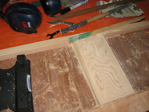
A few photos from last night's sawing and chopping:
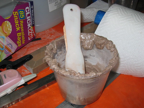
1. The excess glue from the last run (cheer clamp). It's probable that I squeezed out too much! The original amount made up was two pumps resin, one pump hardener, at approx. 7.5 ml per pump stroke, plus approx 4 heaped soup spoons (see previous photos) of high-strength filler powder.
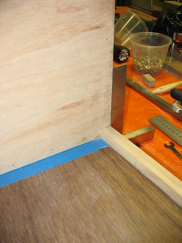
2. Guide tape at stern transom cut line on chinelog: yet another use for blue tape :). I decided to try this a way of creating a high-contrast line exactly 19 mm parallel with the end of the chinelog (cut flush with the relevant end of each panel). This avoided having to draw the line, being lazy!
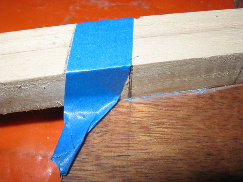
3. Cut made next to guide tape for stern chinelog trim. Note the nice thin kerf :). Also note the pesky little strip of blue tape that has been overlooked and will have to be dealt with using the real and now somewhat blunt chisel, now. See how useful the photos are (for me)? I didn't see that until I looked at the photo, whereupon it leapt up and bit me.

4. Tape removed

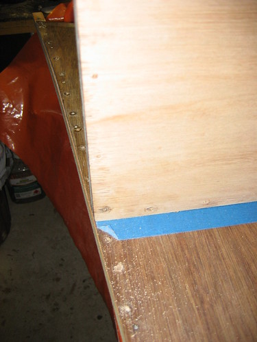
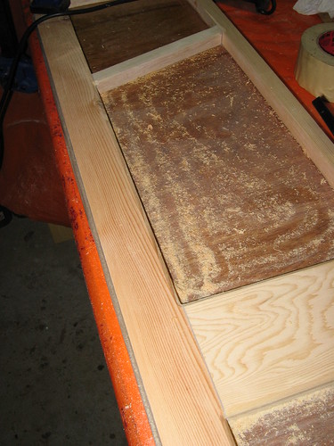
5. Waste removed and ply cleaned up: stern end of starboard side panel.
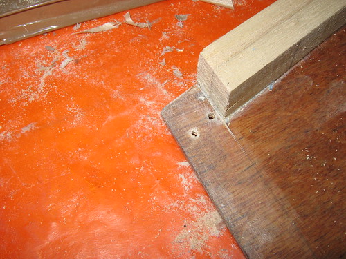
6. Sharpness of cut evident (bow end)
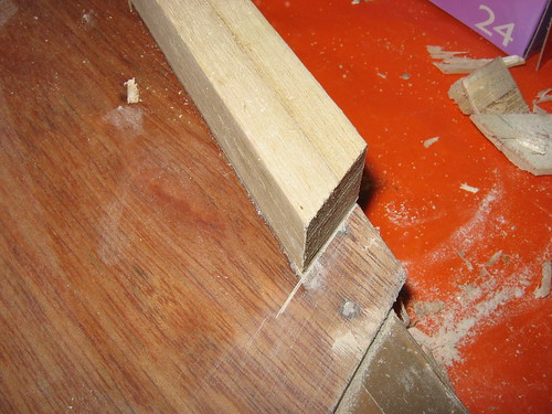
7. Relatively smooth cut too, especially compared with, e.g., the cut resulting from a conventional saw's tooth-set. Sawing technique still needs a bit to be desired, although the Paulownia is quite soft (my feeble excuse ;)
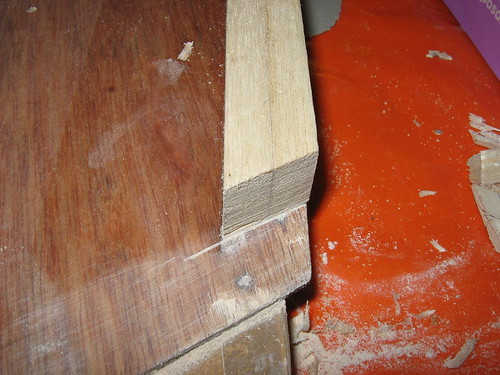
8. Permagrit wedge block in use trimming the port cleat of stern transom. The Permagrit block comes into its own here, as the extrusion that the grit sheet is mounted on is square, enabling cutting back of 90 degree joints. The ply offcut raises the block to the height of the transom panel and suports it for even sanding (in vertical plane). Resin layer is sanded off the transom tab. Note that I wouldn't be doing this on the other (epoxied and sanded) face of the side panel! This side will be epoxied, high-build-prmned, undercoated and given a nice smart coat of Brightside yellow :)

9. Sanded joint cleaned up for inspection: almost finished, but not quite...
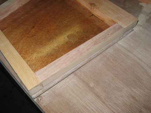
This was all done last night (Monday). I also marked the position for the centre pivot of the Dremel router circle guide, for cutting out the 150 mm inspection port opening. This point was the mirror image of the centre of the prominent roundish grain feature on the cockpit bulkhead, which I deliberately installed towards the bottom for the purpose of using it to locate the port. The pictures (tomorrw) will make this clearer than my somewhat garbled description.
Relatively little was done today, but I cut the inspection port hole out, and did more (strictly unnecessary) cleaning up of the bulkheads, and trimming and fitting of the CB and bow transom onto the side panels. The cleaning up was a good chance to play with the new belt sander: wow, have to be careful with that one, it has TEETH! (Makes the Permagrit look feeble by comparison!) The CB was fitted to both side panels: I only checked the BT on one panel before calling it quits for tonight. I took almost 60 photos today, mostly for my own consumption: I intend to put up a maximum of around 10 % of these! I've found that looking at the photos enlarged gives me a good appraisal of what's going on - things that I miss with the naked eye, now that I've got long-sighted (e.g., the fragment of blue tape). Today's photos tomorrow. Maybe I'll get caught up by then.
-
1st April 2009, 11:20 PM #209
GOLD MEMBER
- Join Date
- Jan 2009
- Location
- Blaxland, Australia
- Age
- 65
- Posts
- 2,551
Here are some pictures from yesterday.
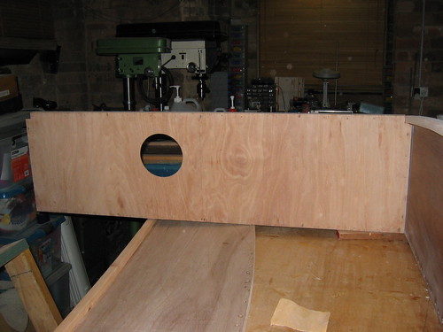
1. Setting up to cut the inspection port hole. This is a good example of the camera picking up what I missed! The bit is actually over the line, not behind it as I had thought. The port is a reasonably good fit, nevertherless.
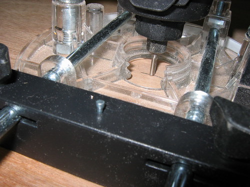
2. One pass around the clock with the little Dremel router. Nice sharp bit!
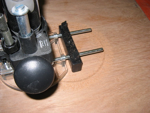
3. Final pass. Looks as though I'm getting rid of a bit of resin with Prooftint stain in it (from the CB incident). Bonus!
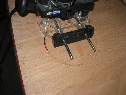
4. Cut complete. The block was a belated addition to support the centre pivot/disc as the full-depth cut exceeded 50 %. The block should have been there to start with. Hence the funny incursions into the cut out disc: it was fortunately not the other way round!
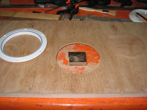
5. The centre of the grain feature and the centre of the port are mirrored. Seemed like a good idea at the time...
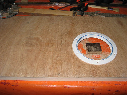
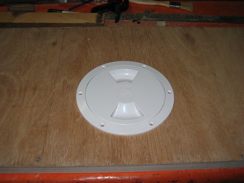
6. Nairn 150 mm inspection port in place
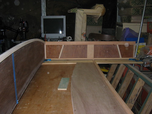
7. Bow transom bottom edge pretty close to its final position. In the next photo you can see...
8. Snap! Bingo! I love it when things turn out this way! The top edge of the BT is in exactly the correct spot! Which means that I got MIK's measurements correctly translated! Fantastic!

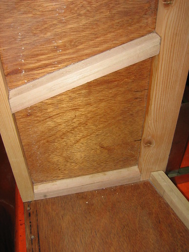
9. Cockpit bulkhead: trial fitting the chinelog cutout
10. The top is a bit too low, however. I'm going to have to add a cap strip and plane it back, to make up for the missing "meat", otherwise the foredeck isn't going to have much to glue on to along that edge.
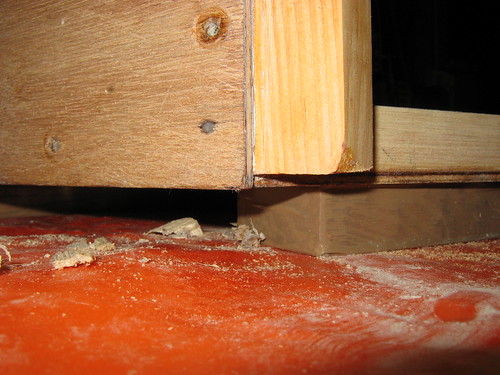
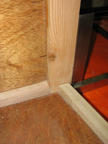
11. Quick check of stern transom chinelog cutout. looks OK...
12. There's quite a bit of room for glue there, though! I think I spent some time on the transom tab subsequently, which will have closed the gap up a bit. This will get checked again when I trial-clamp this joint. The square is there to keep me lined up while I take the photo.
I'm still a day behind getting up to date; never mind. At lease I didn't use all 60-odd photos ;). I ended up binning quite a few out-of-focus/under-exposed ones anyway.
-
1st April 2009, 11:48 PM #210
GOLD MEMBER
- Join Date
- Jan 2009
- Location
- Blaxland, Australia
- Age
- 65
- Posts
- 2,551
The replacement dust pre-filters for the heavy duty snout protector that I'd ordered yesterday from Fibreglass Materials Services at Seven Hills arrived this morning in the post. Fantastic! Thanks guys! This has made using the respirator much more comfortable to wear and less liable to leak around the edges :).
An afternoon of plodding along, cleaning up joints and doing some sanding that will be easier with the boat in its CKD form than when glued together. About half of the sanding was cosmetic, and centred around the stern transom cleats. I had intended to do two sets of edges at 45, and a third a 3 mm roundover. The chamfers went fine using the little Dremel router attachment - nice and neat. The roundover wasn't so good. I spent an hour or so degreasing the Elu from its storage condition, then mis-adjusted the depth of cut, with the bit cutting too low and producing a ledge - something that I didn't want.
Cursing a bit, I decided to hide my mistake by rounding over the edge to a radius of more like 5 mm or a bit more. Cheating, I know, but it looks a lot better, and I enjoyed hand-sanding the ledge out (with bare paper, no block) and making a nice fair curve (in cross section) on both sides of the transom. The bit concerned was the bottom edge of the stern top cleat, so a bit of extra rounding there is not really a problem aesthetically. The inside top of the cleat got rounded over at the intended 3 mm, from the point where the side tank panel will join onto the transom (on both sides).
Similarly, the outer edge of the chinelogs got a bit of a rounding over in the exposed (cockpit) section - about 1.5 - 2 mm, using a piece of 120 grit sandpaper, hand-held. Just before this I started stripping back the table so that I can finally dismantle it, to give me room to set up the boat on the floor (which is flat and level :). Final shaping of the chinelogs to the hull bottom line was done after this.
Also did some initial playing about with corner clamps, test-assembling a side panel to the stern transom. This resulted in some more surgery to the side panel cutout - it fits now, with room for some glue :).
Photos:
1. Chamfering of the bottom cleat and the centre stiffener, stern transom. An attempt to reduce the number of dings in these edges and pretty this bit of the boat up a bit. Overdone?
2. 45 degree chamfering complete
3. All the rounding over finished as well

4. Some of my home-made aero-modelling sanding tools came out for the occasion, but I ended up mostly using a sheet of sandpaper without a block

5. Quick setup to see what it looks like :). Found a joint that needed attention...
6. Another "see what it looks like" mock-up. Nice round hole in the CB, courtesy of the Dremel router attachment. Cool :).
And now I'm up to date. Tomorrow may see the temporary demolition of my temporary table and a more serious pre-assembly of the five bits. Unless I find that I still have more work requiring the table, e.g., joints that still need tweaking, etc.


 Reply With Quote
Similar Threads
-
New Queensland PDRacer Build
By duncang in forum Michael Storer Wooden Boat PlansReplies: 71Last Post: 26th April 2012, 08:30 AM -
Oz PDR build in Adelaide - sexy black PDRacer
By m2c1Iw in forum Michael Storer Wooden Boat PlansReplies: 39Last Post: 27th April 2009, 06:30 PM -
OZ PDRacer - Dylan's build in the Philippines
By Boatmik in forum Michael Storer Wooden Boat PlansReplies: 16Last Post: 23rd February 2009, 05:50 PM -
Brisbane Timber and Working with Wood. Boatmik/PDRacer
By Boatmik in forum Michael Storer Wooden Boat PlansReplies: 1Last Post: 11th April 2007, 08:06 PM -
Flawed wood on the TS --DUCK!
By Robert WA in forum WOODWORK - GENERALReplies: 7Last Post: 19th February 2004, 11:42 AM
Tags for this Thread
balanced lug,
boatmik,
build,
dacron(tm),
douglas fir,
duck,
enamel,
epoxy resin,
fibreglass,
hoop pine,
interminable,
lug,
machinery,
materials,
michael,
oregon,
oz racer mk 2,
ozracer,
paint,
paulownia,
paulownia/glass mast,
pdracer,
plywood,
polytarp,
primers,
really simple sails,
sail-making,
sailmakers thread,
sanding,
storer,
sydney,
timber,
tools,
varnish,
verbose,
western red cedar,
wood,
wood duck,
wrc
