

 Thanks:
  Likes:
  Needs Pictures: 0
 Picture(s) thanks:
Results 856 to 870 of 3347
-
4th October 2009, 10:34 PM #856
 GOLD MEMBER


- Join Date
- Jan 2009
- Location
- Blaxland, Australia
- Age
- 65
- Posts
- 2,551

I was discussing the coating of the cockpit with Martien today - his view was that the extra weight and cost was not worth it - more important than the aesthetics of a lumpy coat that would be difficult to sand back.
So I'll stick to the original three resin coats for the cockpit and hull exterior. The buoyancy tanks two side and one front will all have the extra coat, to seal up the joins as a final water barrier. The finish doesn't matter and it seems a reasonable compromise to me.
Finished off the external fillet for the port tank this evening. Next step is to glue the port side deck on once I get the new bucket of HS powder that I've ordered from BoatCraft (and will also be enough for most of the Goat too, if I'm more parsimonious with the glue than I have been with the 'Duck). In the mean time I'll do some work on the mast partner and trim down the starboard tank panel with the belt sander - the latter one of Martien's suggestions: I'd completely forgotten that I had the thing!
-
4th October 2009 10:34 PM # ADSGoogle Adsense Advertisement
- Join Date
- Always
- Location
- Advertising world
- Age
- 2010
- Posts
- Many
-
6th October 2009, 09:05 PM #857
GOLD MEMBER
- Join Date
- Jan 2009
- Location
- Blaxland, Australia
- Age
- 65
- Posts
- 2,551
Thanks to BoatCraft Pacific and Fastway couriers, I got my rush order of high-strength fillet (glue) powder just after 9:45 this morning :). Only to be dragged off to watch G-Force with my daughter and two of her friends. That sounds as if it was onerous - it wasn't: we all enjoyed the film (it's about a rather unlikely troupe of guinea pigs), and I liked it much more than I was actually expecting. Anyway, I got on to the port tank coating and side deck glueing as soon as we got home. I've just finished the final clean-up and have left it alone to cure.
Over the weekend I put the mast partner runners through the saw to clean them up, then marked the ends on one piece, stuck them together with double-sided tape, then back to the TS and trimmed both pieces to exact length and cut the mitred ends. The partner installation is the next step once the glue on the port side deck has cured sufficiently that taking off the foredeck and subsequent movement of the cockpit bulkhead doesn't shift under the side deck and crack the new glue layer.
The last major glueing process on the hull proper will be that of the foredeck to the hull, once the partner is installed, the hull number painted on (I haven't forgotten!), the damaged-and-patched hull sided sanded smooth (see back several months regarding this little drama), and everything in the front tank given a final sealing coat of resin.
Photos once I've sorted them all out, as usual. There's quite a few, so I'll put them up in several posts, once I've culled them and captioned the remaining ones.
-
7th October 2009, 09:09 AM #858
GOLD MEMBER
- Join Date
- Jan 2009
- Location
- Blaxland, Australia
- Age
- 65
- Posts
- 2,551
Photos of starboard tank, followed by setting up for port tank.
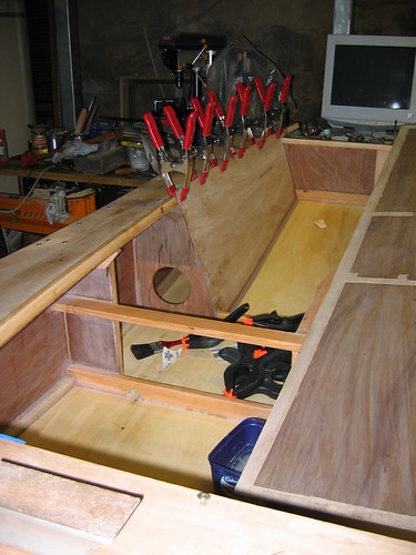
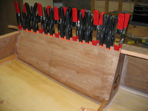
1. Starboard side deck glued down, including the final clamping of the starboard tank. Port side deck waits (very) patiently for its turn
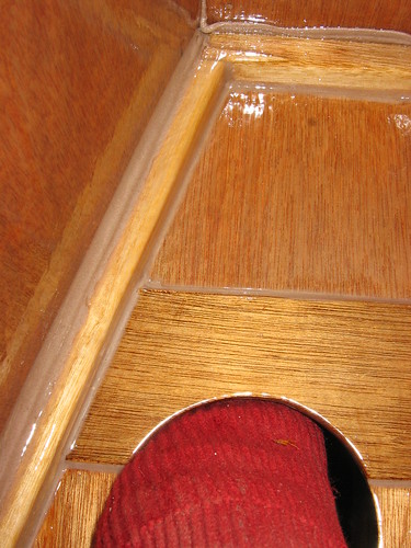
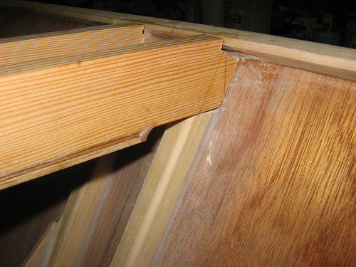
2. Fuzzy close-up of starboard tank and fillet: I've taken numerous photos of this view, and I'm still foxed by not getting sufficient depth of field. You can, however, see where I missed cleaning up some glue residue on the fillet side of the masking tape. I moved the tape closer to the fillets for the port tank installation ;)

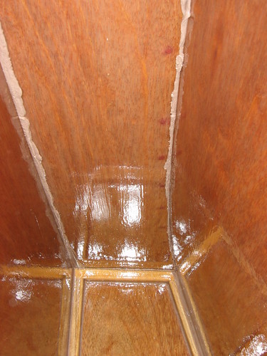
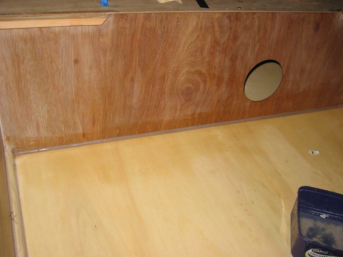
3. Inside the completed starboard side tank. I couldn't reach in to form the usual fillets, so the glue ooze had to stay as it was. To say that I was unhappy about the overall surface finish was an understatement! Taking this series of photos was probably useful in that I've decided to skip the final (fourth) resin coat on the cockpit that I had intended to do. Less cost, less weight, less sanding, less time taken...

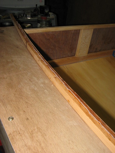
4. Longer view of starboard tank, showing more of the glue extrusions and my lovely van Gogh-like brushwork. I used less resin when coating the port tank - more a function of the viscosity of the new resin and the temperature, rather than by design. Still, it does look reasonably waterproof!
5. Photo taken looking forward: more glue extrusions, and an unintended self-portrait of the "photographer's" arm
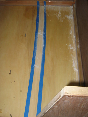
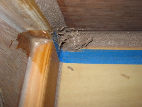
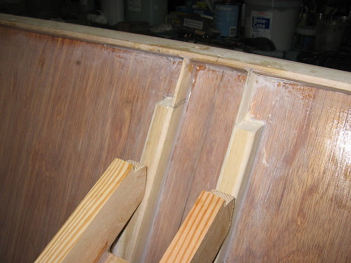
6. Setting up for the port glue fillets: LH line is the outer face of the tank, the RH line the inner; pencil marks at intervals are the markers for the masking tape runs. ***Note that because of the angles of the tank face to the hull bottom, the fillet on the inside of the tank face is quite a bit larger than the one on the cockpit side. You would have to use a larger (40 - 45 mm) radius filleting stick for the cockpit fillet if you wanted them to be closer in size. The Designer didn't think it necessary, and it would add a bit more to the parasitic (i.e., unnecessary) weight bill....
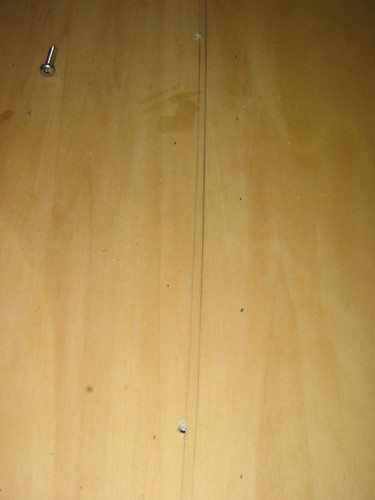
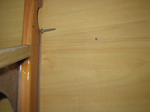
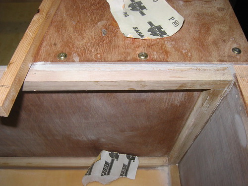
7. Forward holding screw, screw hole and markup
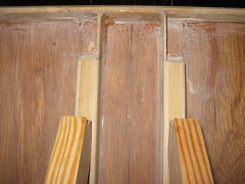
8. Masking tape in place; filleting regions and some glue blobs from the sealing of the chinelogs partially sanded
9. Glueing regions on the port tank face primed: neat 2:1 BoteCote, as usual

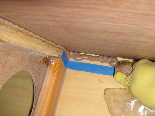
10. Glueing the port tank face on: adding the glue bead to the F2 outer panel cleat. This is one reason why I ran out of glue powder! Over-estimating previous jobs (e.g., glueing on the starboard side deck) also contributed...
11. More "profligate" use of glue: on the stern diagonal cleat this time. While it looks like a waste of glue - and in one sense it was - the areas in this and the preceding photo are where you really don't want a dry joint. Although on reflection, there's no joint on a boat where you can afford to have it too lean or incomplete. Perhaps I ought to take up cake-icing in my spare time (just kidding, he said hurriedly!)
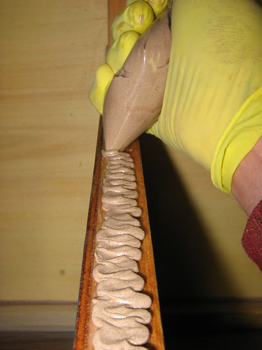
12. Starting the internal bottom glue fillet: lots and lots of glue! I had to mix up another batch after applying this lot. The weird looking Blobby Yellow Thing is my hand ;). Note that although there appeared to be a lot of glue in the photo showing the glue being applied to the F2 cleat, there isn't as much ooze as one might have expected. In fact, I had to add extra glue to form the 10 mm radius fillet. This was partly because the cleat had been sanded back heavily towards the side of the boat, to allow clearance for the tank side and - space for glue!
Next post will finish off the port tank glueing process, plus some photos of further (intentional) filleting
-
7th October 2009, 11:13 AM #859
GOLD MEMBER
- Join Date
- Jan 2009
- Location
- Blaxland, Australia
- Age
- 65
- Posts
- 2,551
Photos of starboard tank construction, continued...
1. This photo is slightly out of sequence... Close-up of starboard side deck/tank side join: tank side planed down to the glue-line. I cleaned off the glue ooze as I went: added a clamp, removed the clamp in between, removed the glue, put back the clamp. added another clamp, etc., until I reached the end of the tank face. That way, I'll b able to plane down to the carlin, instead of using the belt sander. Quieter, and less messy :)
2. Port side tank glued onto its vertical supports; internal fillet added; tank face comprehensively clamped while the glue sets

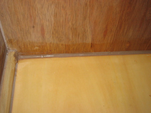
3. Close-up of port tank internal bottom fillet. Tape and glue blobs were removed at second clean-up stage (remove clamps, unscrew deck, remove tape and clean up resin, fair fillet ends, replace deck, replace clamps...)

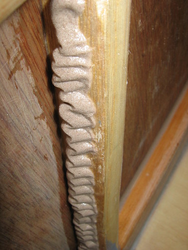
4. Port tank front internal vertical fillet, completed
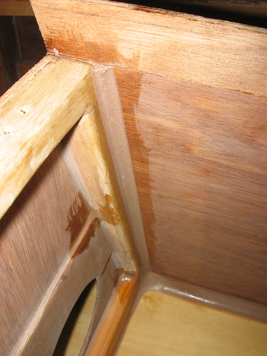
5. Front end of internal tank fillet prior to fairing
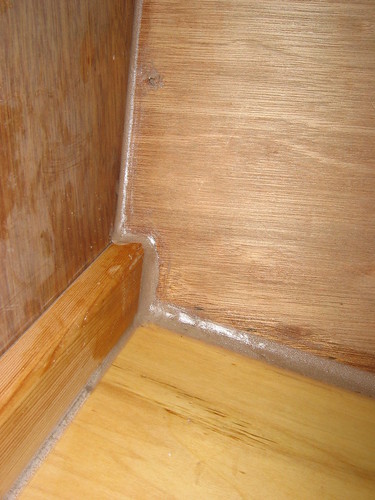
6. Front end of internal tank fillet, fairing complete
7. Stern end of internal fillet prior to fairing. Note that 10 mm radius vertical fillet is already completed. Some glue clean-up on tank face needed...
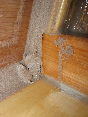
8. Stern end of internal fillet, fairing complete

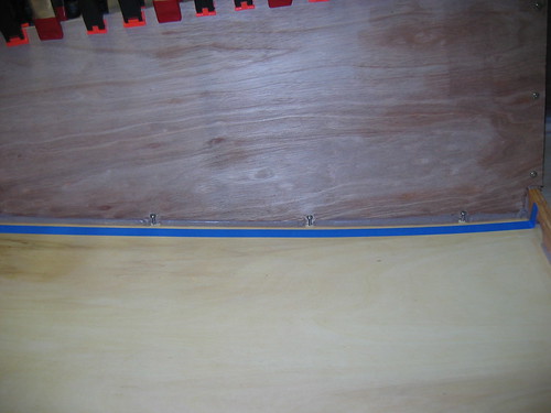
9. Partially completed port external bottom tank fillet. Instead of wasting the excess from glueing on the the port tank side, I squeezed as much as I could of it into four non-contiguous segments between the three bottom-edge securing screws, with gaps around the screws to leave them clear. The idea was that when the screws were removed, there wouldn't be as much filleting to make up, and the gaps will acts somewhat as keys (although not very much). It worked quite well, in the end
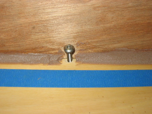
10. Close-up of tank side bottom-edge-retaining screw and partial fillet. Note the gaps around the screw, so that it was less likely go be glued in place. Since much smaller screws are removable from the glue after it has gone off, I probably could have gone right around the screws, although cleaning up the tank wall around the screws would have been more difficult
11. Cockpit floor filleted with excess glue from port side tank installation. The glue used here would have been enough to complete the external fillet, but the screws would have left holes to be filled, and I actually didn't think of filling around them. ice cream container contains methylated spirits for dipping paper towels into when cleaning up excess glue blobs and smears
...
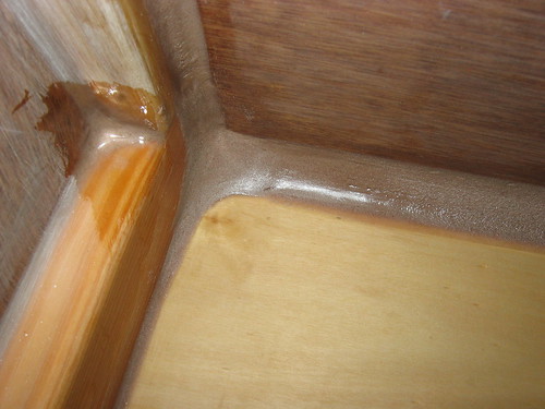
12. Close-up of cockpit floor fillet: it's a bit lumpy, and will probably get a final skim-coat of glue eventually. Note that the 10 mm radius of this particular fillet was entirely deliberate: extra sealing of the front buoyancy tank
All fillets in the cockpit will get a coat of resin prior to varnishing - after the resin has cured it will get faired onto the rest of the cockpit surfaces using sandpaper - but that will be a lot easier than sanding an entire-coated cockpit! More photos of various subsequent activities to follow...
-
7th October 2009, 04:36 PM #860
GOLD MEMBER
- Join Date
- Jan 2009
- Location
- Blaxland, Australia
- Age
- 65
- Posts
- 2,551
Slight hiatus in the port side deck installation was filled in with other useful activities:
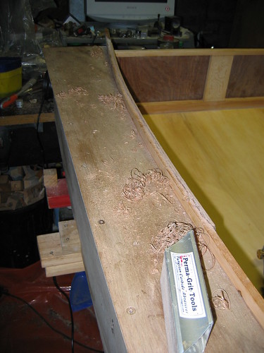
1. Sanding down the starboard tank face excess using the Permagrit block. This took a long time, and I eventually used the belt sander - once Martien had reminded me that I had one!
2. Partial tank fillet sanded back to allow free travel of filleting tool - I'd put more fillet down than I'd realised!

3. Top coat added to partial fillet so it's now complete (I had enough HS-powder left for that! :). Fairing of ends yet to be done
4. Rear end of external fillet faired off
5. Forward end of fillet, unfaired
6. Forward end of fillet, faired; screw holes partially filled
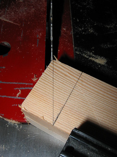
7. Lining up the cut line for the front of the mast partner runners. Runners are taped together using 3M double-sided tape, and have been cut to the right length per plans (540 mm). I initially used elementary trig to get the angle for the mitre gauge (arctan(opp/adj)), which was almost right - my drawing of the line must have been slightly off. At any rate, I decided to go with the line as drawn and line the gauge up using the straight edge and runner line. The difference is only minor, and once the runner is introduced to its final home, it may all change, anyway. I might go out on a limb and say that it will definitely change!
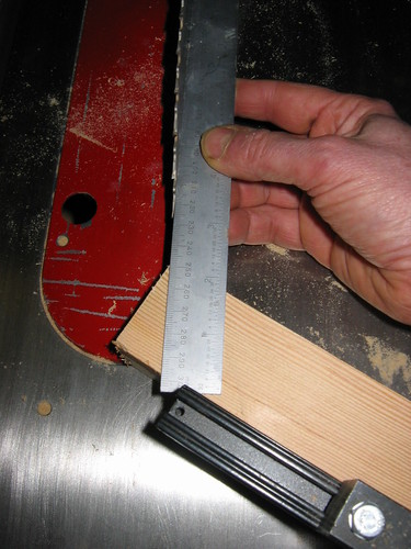
8. Front ends of runners ready to go through the table saw. Note the thin-kerf (CMT-brand) blade that I use
9. Various mast partner parts: two runners taped together with double-sided tape, cut to length and angles with hardwood-spacer lines drawn on (rear line is incorrect and needs to be redrawn); ply gussets (2 x laminations of 0.125 " birch a/c ply) - RH (front) plate has position for 20 mm diameter drain hole marked in; and mock-up of mast-section (made to gauge glass-resin thickness of Paulownia strengthening jacket - see a much earlier series of posts regarding this)
I'll start another post rather than stuff this one full...
-
7th October 2009, 05:03 PM #861
Grumpy old Bugga
- Join Date
- May 2003
- Location
- South Oz, the big smokey bit in the middle
- Age
- 67
- Posts
- 4,377
There are no photos so therefore, Martien does not exist. He is, in reality, your imaginary workshop partner whom you have created as a defence against the mind crumbling vapours rising from all that epoxy Originally Posted by AlexN


Richard
(it's okay, mine's named Baz )
)
-
7th October 2009, 06:13 PM #862
GOLD MEMBER
- Join Date
- Jan 2009
- Location
- Blaxland, Australia
- Age
- 65
- Posts
- 2,551
Getting close to the end of the side-deck/tank installation photos...
1. Starboard side tank sanded down to carlin-level with belt sander and cork block/papers. Tank face is covered with fine powdery dust
2. View of sanded tank side from above
3. Final stage of deck installation: side deck glued and clamped in place
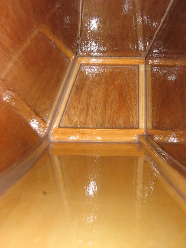
4. Internal view of port side tank: surface finish is possibly slightly better than the starboard tank - certainly a bit thinner - but as long as it's waterproof, who cares! Interesting reflections of the end panel...
5. View aft showing both completed tanks
6. Port side deck glued on: you can tell because of the sudden increase in the number of screws ;). The (clear) packaging tape is just visible if you squint a lot and use quite a bit of imagination...

7. Both side decks in place, and foredeck removed to continue work on the mast partner - plus the unfinished secondary clean-up in the buoyancy tank, carrying over from the hull bottom glueing

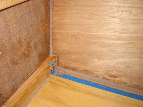
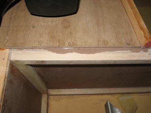
8. Glue seepage under the foredeck: this is precisely why Michael says to use packaging tape here. I did - the foredeck lifted straight off - but it took a while to remove the glue, at even less than 24 hours and cool weather, too. Looks as though I was too heavy-handed putting those screws in - and forgot to use the buffered screws again...
9. Port side of cockpit bulkhead forward of side deck has been cleared of the glue seepage: lots of scrubbing with the Permagrit block!
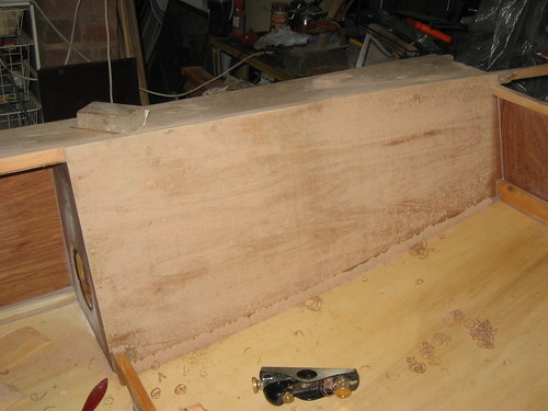
10. Forward buoyancy tank again - remember this, anyone? I do, to my great shame :(. Memory lane, ha ha <shudder>. The damaged panel has just been subjected to a vigorous scrubbing with 60- and 80-grit paper, to smooth off the lumpy resin coat used to cover the repairs - and the entire panel surface!
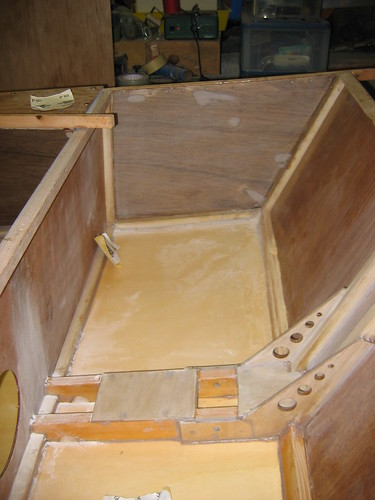
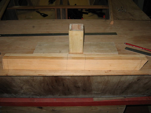
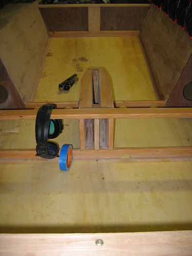
11. Same view of forward tank, with mast partner runners posing just for show ;). Bit of notching and so forth to be done at the ends...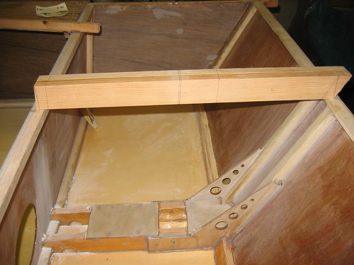
It's back to fiddling with the partner runners now...
-
7th October 2009, 06:17 PM #863
GOLD MEMBER
- Join Date
- Jan 2009
- Location
- Blaxland, Australia
- Age
- 65
- Posts
- 2,551
Hi Richard, Originally Posted by Daddles
Actually, there are some - a few weeks back! I defy you to go looking for them ;). Then again, maybe he is imaginary. What is this place? What is this wooden box thing?
Whatsisname :)
-
8th October 2009, 12:35 AM #864
Happily receives emails.
- Join Date
- Jul 2005
- Location
- 'Delaide, Australia
- Age
- 65
- Posts
- 8,138
Those filleting shots are quite instructive! Very nice. Shows the clean way and also shows the fillets can look pretty ordinary at some stages.
For other readers the little fillets down the sides of solid wood joining ply are not needed ... Alex is having fun!
MIK
-
8th October 2009, 09:52 AM #865
GOLD MEMBER
- Join Date
- Jan 2009
- Location
- Blaxland, Australia
- Age
- 65
- Posts
- 2,551
Filleting practice - for the big ones ;) Originally Posted by Boatmik
Alex.
-
8th October 2009, 09:13 PM #866
GOLD MEMBER
- Join Date
- Jan 2009
- Location
- Blaxland, Australia
- Age
- 65
- Posts
- 2,551
I had an inkling that there was likely to be some fun and games with the mast partner when matching it up with the rest of the structure. I was right...
* The mast step bolt is in pretty well the position given in the plans, give or take 0.5 mm <snigger>;
* the fore and aft edges of the mast step opening are 5 mm aft of their positions on the plans;
* cockpit bulkhead forward face to bow transom aft face at sheer line = 531 mm: 9 mm shorter than given partner runners (540 mm);
Nothing can be done about the CB being too far forward by 9 mm (now that the side decks have been glued down ;), but I can do some simple, minor "surgery" on the mast step fore/aft faces via addition (aft) and subtraction (fore). The "short" tank doesn't affect the position of the step bolt, which is correct
The mast partner itself doesn't have to change, given the correct position of the step bolt. I think the step problem came about by adding a 100 mm plate to the front of the step (per the plans), even though the position of the edge of the forward block was 95 mm (on the plans). Should have thought that one through a bit more at the time - or read the plans a few more times!
There are some photos:
1. First fit of partner runners; the dust is from last night's flurry of sanding in the tank
2. Apparent bow in both bulkheads: I initially put this down to distortion by the wide angle of the camera lens, but decided to eyeball them independently, and the bow was apparent there too. The bow is exaggerated by the camera, but it is there in reality. I then measured the distance between the bulkhead faces with the partner runners removed, and the distance was 531 mm - 9 mm short of the 540 mm length of the runners per the instructions. I now remember having taken quite a bit off the aft end of the step runners, which suggests that the whole bulkhead is too far forward, not just the top. Hmmm...

Having thought this all through, I'm confident enough to proceed with re-drawing the partner block positions in again - I'd rubbed them out (with sandpaper) when I discovered that there was something weird going on. Fortunately, the weirdness is fixable. I suppose that I had better get back to it ;).
-
8th October 2009, 10:38 PM #867
GOLD MEMBER
- Join Date
- Jan 2009
- Location
- Blaxland, Australia
- Age
- 65
- Posts
- 2,551
Well, well. Wouldn't you know it, eh? I've just been carefully looking at the mast step diagrams, and have found my mistake. And it's not in the mast step, but in my rather too-rapid scanning of the first of the two drawings. That is: I was mistaking the front of the ply cheek as being the location of the rear face of the front block, which, of course, it isn't. The blocks in the step are in fact located by the edges of the ply, so their position is correct too, and there is nothing to worry about! Panic over!
I just need to make sure that the mast partner lines are in the right spots, which shouldn't be too hard, ho ho.
The error in the CB position can't be helped at this stage; of course, the CB may be correct and the boat may be 9 mm too short ;). Either way, nothing to worry about, and nothing to be done about it anyway.
-
9th October 2009, 09:55 PM #868
GOLD MEMBER
- Join Date
- Jan 2009
- Location
- Blaxland, Australia
- Age
- 65
- Posts
- 2,551
Today's plan was to get the mast partner glued together today, and resin-triple-coated the thing tomorrow.
I appeared to almost throw the partner together - that's how it felt - but I think I'm starting to get used to the glueing method now and am speeding up a bit. I was careful measuring and dry-assembling, though. The glue is going off more rapidly at the moment - either because of the new batch, or the slightly warmer temperature in the workshop, or a mixture of both.
Photos tomorrow - or Sunday. Got a bit carried away preparing the tank bay for the partner - have photos of that as well...
-
12th October 2009, 10:41 PM #869
GOLD MEMBER
- Join Date
- Jan 2009
- Location
- Blaxland, Australia
- Age
- 65
- Posts
- 2,551
No photos up yet - so what's going on? It's school holidays, plus I've been working on the partner installation and haven't had a chance to update anything.
Mast partner is glued up, sanded clean, glued/screwed into the hull after making sure is was smack on the centreline, and I have spent a bit of time today shaping it to the sheer line. I've got about halfway there: there is still a bit of a hump in the middle of the foredeck when test-fitted over the top. The edges of the foredeck don't drop into place on the sheer clamps, even when pressure is applied on the partner - so more careful spoke-shaving and sanding to be done. I think the "straight-edge" I'm using is drooping at the ends a bit, which is making the process a bit inaccurate; hence the trial fitting using the foredeck.
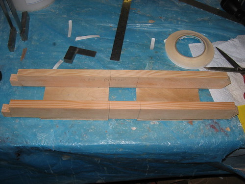
OK, so here are some photos - of the partner construction:
1. Mast partner assembled using 9 mm sail tape, prior to screwing together with 25 mm button head screws. Was going to use 15 mm screws, but used wrong bit (4 mm, instead of 3 mm which got broke)
2. Partner drilled for assembly screws; front gusset in place
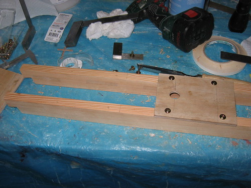
3. Both ply gussets screwed into position: just remove tape and add glue...
4. 20 mm diameter drain hole in front plate: I ran a 25 mm countersink a way into the hole to allow easier flow. The other opening got a quick rub around to break the sharp edge

5. Runners masked. Different sides: top runner is the outside face, bottom runner the inside, with notches for 3 mm radius fillets
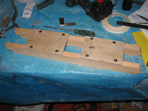
6. Partner re-assembled. Tape removed, remnant goo removed with acetone, glued and screwed back together again
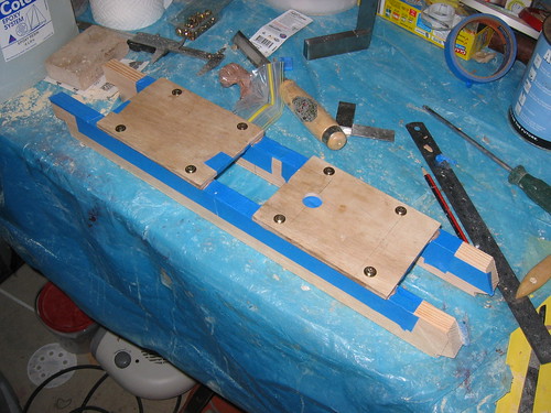
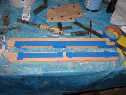
7. Glue ooze awaiting filleting with a paddle-pop stick. Like everywhere else that I've put fillets, they are to allow water to escape more freely and to allow easier mopping up after sailing

8. Rather overdid it on the tape! At least the glue was kept off the timber ;)
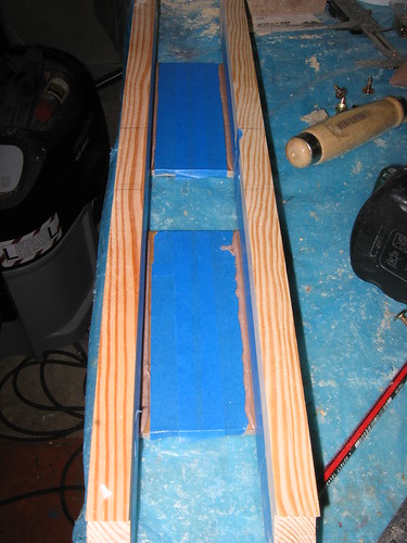
9. Four more screws? The 15 mm screws lost traction once the glue went on, so I whacked a pair of 20 mm screws in in between the each 15 mm set, then replaced the 15s with 25s. Used 20s in the middle holes since I didn't drill - didn't want to run too much risk of splits

10. Partners cleaned up: fillets formed and tape removed
11. Fillets removed in the support block positions: I nearly forgot these - I was viewing the previous photo and realised what I hadn't done, so had to scoot back and fix it up pronto!
More photos once I've sifted through them: this lot was already up on Flickr and was a simple matter of captioning and pasting in...
-
13th October 2009, 07:30 PM #870
GOLD MEMBER
- Join Date
- Jan 2009
- Location
- Blaxland, Australia
- Age
- 65
- Posts
- 2,551
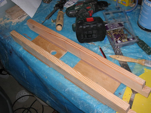
Next batch of photos. These involve tweaks to fit the mast partner to the boat. Mostly hack work with a chisel, plus a small amount of 60-grit sanding. Also some fiddling around with the TS to prepare some hardwood and cut the blocks that fit for and aft of the partner's mast hole
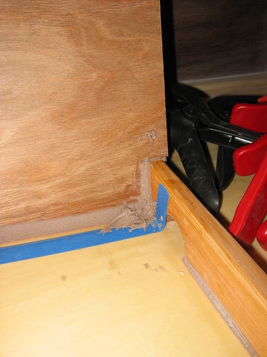
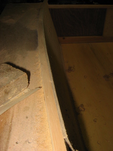
1. Partner fit check, after chopping out the tops of the vertical members using a 20 mm chisel
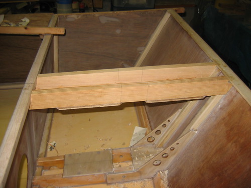
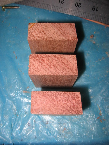
2. Hardwood (Eucalyptus sp.) blocks for mast partner, cut and mitred to partner angle on table saw. The end grain will get close attention from the resin brush, to prevent dry joints! I've also got to remember to insert the block to which the towrope fairlead will be anchored (note that I don't have a lot of confidence in my present sailing skills ;)
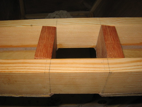
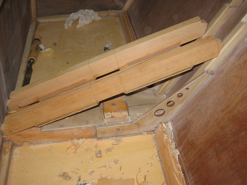
3. Blocks mocked up in the partner: these are not glued in place until the dorsal surface of the partner has been shaped to the sheer line of the boat
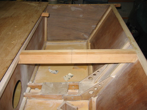
4. Initial partner dry fit, looking forward. Runner top surfaces have not been faired in, yet
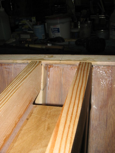
5. View of partner, indicating that there will need to be quite a lot of glue in those forward joints...
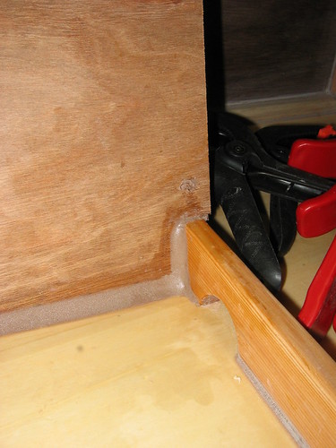
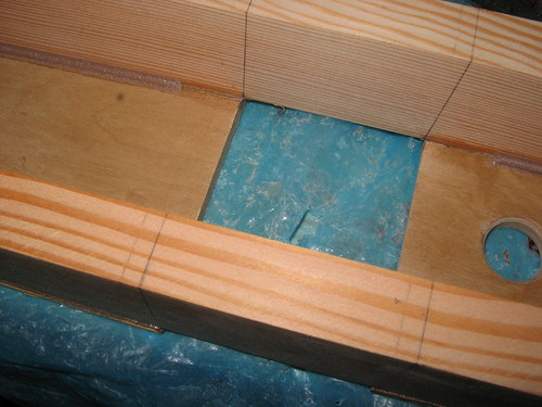
6. Vertical "tow ring supports" trimmed to allow the partner ends to fit where they should. The vertical items are part of the "tender tow ring" set-up that I pinched from the designer to add extra strength to the mast step runners. The grain of the latter runs horizontally, and is a potential split hazard. See a long way back in the posts for the reasoning ;)
7. Small webs left. Some might question the sanity of leaving these thin pieces of timber - but they do allow for a slightly increased glueing area, if not increased strength. On the other hand, leaving them there involved quite a bit of fiddly work, and you can see where I slipped with the chisel at one point (this hole got filled with glue, of course)...
8. Partner awaiting glue: "resting" from its labours, while surrounded by a litter of Paulownia chips
There are more photos, oh yes, there are. Later ;).


 Reply With Quote

Similar Threads
-
New Queensland PDRacer Build
By duncang in forum Michael Storer Wooden Boat PlansReplies: 71Last Post: 26th April 2012, 08:30 AM -
Oz PDR build in Adelaide - sexy black PDRacer
By m2c1Iw in forum Michael Storer Wooden Boat PlansReplies: 39Last Post: 27th April 2009, 06:30 PM -
OZ PDRacer - Dylan's build in the Philippines
By Boatmik in forum Michael Storer Wooden Boat PlansReplies: 16Last Post: 23rd February 2009, 05:50 PM -
Brisbane Timber and Working with Wood. Boatmik/PDRacer
By Boatmik in forum Michael Storer Wooden Boat PlansReplies: 1Last Post: 11th April 2007, 08:06 PM -
Flawed wood on the TS --DUCK!
By Robert WA in forum WOODWORK - GENERALReplies: 7Last Post: 19th February 2004, 11:42 AM
Tags for this Thread
balanced lug,
boatmik,
build,
dacron(tm),
douglas fir,
duck,
enamel,
epoxy resin,
fibreglass,
hoop pine,
interminable,
lug,
machinery,
materials,
michael,
oregon,
oz racer mk 2,
ozracer,
paint,
paulownia,
paulownia/glass mast,
pdracer,
plywood,
polytarp,
primers,
really simple sails,
sail-making,
sailmakers thread,
sanding,
storer,
sydney,
timber,
tools,
varnish,
verbose,
western red cedar,
wood,
wood duck,
wrc
