

 Thanks: 0
 Likes:
  Needs Pictures: 0
 Picture(s) thanks: 0
Results 91 to 105 of 134
-
12th September 2012, 09:10 AM #91
 SENIOR MEMBER


- Join Date
- Jul 2008
- Location
- Fenwick, Michigan
- Age
- 75
- Posts
- 908

Over-simplification is good.

Thanks for the explanation. So, if one were to experiment with this, the top of the boom and the bottom of the yard would be a denser/harder wood than the respective bottom and top...
I'm willing to experiment. All I need to do is find info on the densities of woods, figure out what I can get locally and build a yard or two.Building Gardens of Fenwick, a Welsford Parthfinder
Gardens of Fenwick
Karen Ann, a Storer GIS
Goat Island Skiff - Sacramento
-
12th September 2012 09:10 AM # ADSGoogle Adsense Advertisement
- Join Date
- Always
- Location
- Advertising world
- Age
- 2010
- Posts
- Many
-
12th September 2012, 01:23 PM #92
Better Recognize
- Join Date
- Jun 2009
- Location
- New Hampshire
- Posts
- 960
Yeah, but I think that makes sense if the bendy boom issue was vertical, I think we're trying to counteract horizontal bendy, right?
-
12th September 2012, 05:51 PM #93
Senior Member
- Join Date
- Sep 2012
- Location
- NSW, Australia
- Posts
- 474
I agree it's not relevant for masts. They're loaded all over the place, so you can't optimise them for one direction. Best to just use something normal. Originally Posted by Boatmik

Ok, I was pondering this some more while I was up cleaning the gutters (I find it's always best to be distracted when working in high places) and I think there's something missing. Run this past your olfactory nerve and see how it smells.With the yard there is a mix of a structural requirement for stiffness which tends to set the diameter - and at that diameter there are few failures of the spars to indicate that more tensile or compression strength is needed. Also the spars are relatively small diameter in this size of boat making a hollow spar of heavier species (to match the weight and diameter) too complicated to build.
Another factor is that I did some fiddling with analyses of this type and within small spaces it doesn't really pay off. The reason is that the neutral axis moves towards the stiffer and stronger timber - meaning that more load is put on the heavier timber compared to the light one. This has a bigger effect when the flanges are relatively thick relative to beam thickness.
But for bigger boats - your analysis is right and it can be a worthwhile consideration as loads can be much closer to critical ones where the structure can fail if something is a bit misaligned or set up wrongly.
Best wishes
MIK
The thing is that the Young's modulus that is usually quoted for any timber is just a global average. By that I mean that it will tell you the behaviour of a bending beam as a whole, but it wont tell you about the individual situations on the tension and compression faces. If you take a homogenous section, then according to standard beam theory it will have its neutral axis smack in the middle, but that is based on the assumption that the material will behave the same way in tension and in compression. Timber doesn't do this. To accurately model what happens with a timber beam, you would need to input a separate tensile and compressive modulus for the relevant faces.
This means that an apparently uniform section would in reality have its neutral axis well off centre. To get the neutral axis to really be in the middle, the beam would need to be asymmetrical (either in section or in composition).
So for spars you're sizing for deflection rather than breaking strength. Deflection is the ultimately the result of deformation on the tension and compression faces. How much the timber squeezes and stretches. I don't have any figures at hand, but I'm willing to bet that having a compression strength of about half the tensile strength means that the great majority of the deformation (and therefore the bending of the whole beam) is going to be down to the comparative weakness of the compression side. A good analogy is steam bending, where you deliberately exceed the elastic limit by compressing the inside of the bend. The tension side of the bend doesn't elongate much, if at all.
I think there may be some scope for optimisation here, if it's done carefully. I'm currently inclined to think that the best stiffness/weight ratio for a spar or boom might be achieved by using a D section, or something similar.
-
12th September 2012, 08:10 PM #94
Senior Member
- Join Date
- Mar 2010
- Location
- Queenstown New Zealand
- Posts
- 382
You're mixing up stiffness and strength in the above post. Basically, elastic modulus is the same in compression and tension, even though strength of wood is quite a bit higher in tension than compression. Will try and explain more when I have time.
Ian
-
12th September 2012, 08:57 PM #95
Senior Member
- Join Date
- Sep 2012
- Location
- NSW, Australia
- Posts
- 474
Ok, I think I've got it anyway. You seem to be saying that, providing the beam is within its elastic limits, the amount of compression on the compression face will always be equal to the amount of extension on the tension face.
-
13th September 2012, 12:59 AM #96
SENIOR MEMBER
- Join Date
- Jul 2008
- Location
- Fenwick, Michigan
- Age
- 75
- Posts
- 908
So much for simplification... Got to thinking about it and, half-way through this morning's bike ride, I realized - in my experience - the stiffness we've been measuring of the hollow box spars (yard and boom) does not come from the top and bottom faces. The side faces determine/control the vertical stiffness while the top and bottom faces determine/control the horizontal stiffness. (I realize that, most likely, all four faces provide some component of both vertical and horizontal stiffness, but I have no idea how such components would be measured.)
So, what's happening to the wood in the side faces? Compression? Tension? Where? Does it matter where/how the load is placed? (remember, this is from the mind of a non-engineer... If you stand a 12' long 2x4 on its edge (supported near its ends), does it matter (compression/tension wise) whether the weight is hung from the top (loop of rope) or hung from its bottom edge (say, with an eye-screw into the bottom edge)? Not sure why that question came to mind or whether it has any value at all.
If it is the side faces, what if they are laminated (width-wise) half and half with hardwood and softwood?
Or, does it just not matter in the sizes we are talking about?Building Gardens of Fenwick, a Welsford Parthfinder
Gardens of Fenwick
Karen Ann, a Storer GIS
Goat Island Skiff - Sacramento
-
13th September 2012, 12:59 AM #97
SENIOR MEMBER
- Join Date
- Aug 2010
- Location
- New Jersey, USA
- Posts
- 767
FWIW, Sumbloak's thinking makes sense to me, I couldn't spell modulus if it weren't on the screen in front of me. But I thought I read somewhere that the outer rings of a trunk are better in tension and the inner core is better in compression?
My experience with boom making: I laminated two lengths of Oregon together with the seam parallel to the grain. When I measured deflection, it was far more flexible with the grain (and seam) oriented vertically than with the grain oriented horizontally. Further, the two horizontal-oriented faces did not bend equally. (I repeated the measurements a few times just to get a sample size greater than 1, but I didn't go crazy by repeating >30 times.) I ended up rejecting that stick and laminating a new, slightly thicker one from tighter grained lumber (still Oregon, still square section). The new one was stiffer and the opposing sides were far more equal, but there was still a distinct difference between vertical and horizontal grain results.
My conclusion? These spars still have the spirit of tree in them. Work with the tree-ness within and you'll have a happy spar. I can certainly believe that using a layer of wood--be it another species or the compressive portion of a log if that's actually true--on the compressive face can make some difference. These things are so variable, like the living beings they once were. Mix and match and bring different strengths and properties together and you'll have a whole team of trees working for you. Too bad we can't have spars that bear fruit during those long windless days...Dave
StorerBoat Builder, Sailor, Enthusiast
Dave's GIS Chronicles | Dave's Lugs'l Chronicles | Dave's StorerBoat Forum Thread
-
13th September 2012, 02:37 AM #98
SENIOR MEMBER
- Join Date
- Jul 2008
- Location
- Fenwick, Michigan
- Age
- 75
- Posts
- 908
Huh... Thanks for trying to explain this stuff but, FWIW this is making less and less sense to me. I can see that grain orientation makes a difference (and I may have just figured out how to improve my spars) but I'm not sure I understand what you describe in your second paragraph - other than you got mixed results.
Honestly, the terms, "compression" and "tension" have no meaning to me and "modulus" means even less (my eyes glaze over as I read such stuff). I'll just plod along experimenting (yards and booms are inexpensive to build) until I come up with spars I'm really happy with.Building Gardens of Fenwick, a Welsford Parthfinder
Gardens of Fenwick
Karen Ann, a Storer GIS
Goat Island Skiff - Sacramento
-
13th September 2012, 08:59 AM #99
Senior Member
- Join Date
- Sep 2012
- Location
- NSW, Australia
- Posts
- 474
Sorry, you're wrong. Originally Posted by BobWes
Shear. In terms of vertical loads, the side faces only exist as spacers. Think of them like the foam core in a foam sandwich panel. When the spar is loaded vertically, the side panels are just core spacers in shear (or near enough to it). When the spar is loaded horizontally, the middle of the top and bottom spacers are the same. When loads are all over the place, all the faces are taking some of the load.So, what's happening to the wood in the side faces? Compression? Tension?
-
13th September 2012, 09:03 AM #100
Senior Member
- Join Date
- Sep 2012
- Location
- NSW, Australia
- Posts
- 474
My thinking doesn't make sense if Ian Howick is right about the elastic modulus being the same in tension and in compression. Originally Posted by davlafont
If that has been verified experimentally for a range of timbers, then there would be no point in mixing species and using odd sections. A basic box section built out of one species would be best.
-
13th September 2012, 11:13 AM #101
SENIOR MEMBER
- Join Date
- Jul 2008
- Location
- Fenwick, Michigan
- Age
- 75
- Posts
- 908
Well, since I don't understand this stuff, I'm not surprised to be wrong. We can add shear to the list of terms I don't understand.
So, why is a hollow box boom measuring 75mm (sides) x 35mm (top & bottom) stiffer (in the vertical direction) than one measuring 65mm (sides) x 35mm (top & bottom) (both made of same material with same wall thicknesses)? ("Vertical," to me, is pulling up or down on the boom when it is supported on the narrow bottom; "Horizontal" is pulling up or down with the boom on its side. Guess I could be wrong about vertical and horizontal, too.)Building Gardens of Fenwick, a Welsford Parthfinder
Gardens of Fenwick
Karen Ann, a Storer GIS
Goat Island Skiff - Sacramento
-
13th September 2012, 11:42 AM #102
Senior Member
- Join Date
- Jul 2012
- Location
- Santa Cruz La Laguna
- Posts
- 134
OK - I have a Civil Engineering Degree but have never practiced in this field, so I feel like I have enough knowledge to be dangerous here (especially as I haven't been on a Goat or yet made either a boom or a yard).
My understanding is that the goal is to increase stiffness in the vertical plane of the boom/yard. So my thought is to borrow a design element from the inwales which could be used to increase stiffness in this plane (possibly a lot?) for a weight increase of 15-25%. Below is a side profile of a the boom/yard design I have been thinking about.
The 40mm by 40mm section is replaced by two 40mm x 20mm sections. In between these two sections spaces would be inserted with the thickest spaces placed where the bending moment is greatest (the image has this at the center but I think the plans indicate that this is 1/3 along the length of the boom/yard). In this example I have the "biggest gap" set to 30mm which would increase the distance from the top and bottom surfaces from 40mm to 70mm (20mm + 30mm + 20mm) in the centre. The ends effectively have an unchanged cross-section but the bending moments should be much smaller in these locations.
I don't think the stiffness in the horizontal plane should suffer (depending on how the sail is attached). However it is possible that the surface in compression (from vertical loading) could twist/deflect horizontally due to excessive loading (which can be a problem with I beams) - but I suspect the section would have to be significantly deeper for this to occur.

https://picasaweb.google.com/1153149...04258527052754
It could look neat or ridiculous - certainly different. It would take more work to make, paint and will weight more (dependent on spacer size, spacing and timber used). I don't know if there would be any problems with the rigging (either attaching or interfering with the rigging) - I have no experience in this area.
-
13th September 2012, 11:55 AM #103
Senior Member
- Join Date
- Sep 2012
- Location
- NSW, Australia
- Posts
- 474
Because what you have effectively done is to increase the core thickness of the "sandwich", which moves the top and bottom skins further apart, which lowers the stress in them (because they have more "leverage" against the neutral axis) which means they deflect less coz they're effectively more grunty. Originally Posted by BobWes
-
13th September 2012, 12:00 PM #104
Senior Member
- Join Date
- Sep 2012
- Location
- NSW, Australia
- Posts
- 474
Might work well with a sleeve (or pocket) luff on the head of the sail. I've often thought that would be the best way of doing the head for a lug anyway. Neater and simpler that lacing it on. As long as the ends of the sleeve are open to allow drainage in case of capsize, it could work rather well. Originally Posted by surlyone
ETA: Oh and being a civil engineeer and all, can you verify what Ian Howick said about elastic modulus being the same in tension and compression, even for timber?
-
13th September 2012, 12:05 PM #105
Senior Member
- Join Date
- Jul 2012
- Location
- Santa Cruz La Laguna
- Posts
- 134
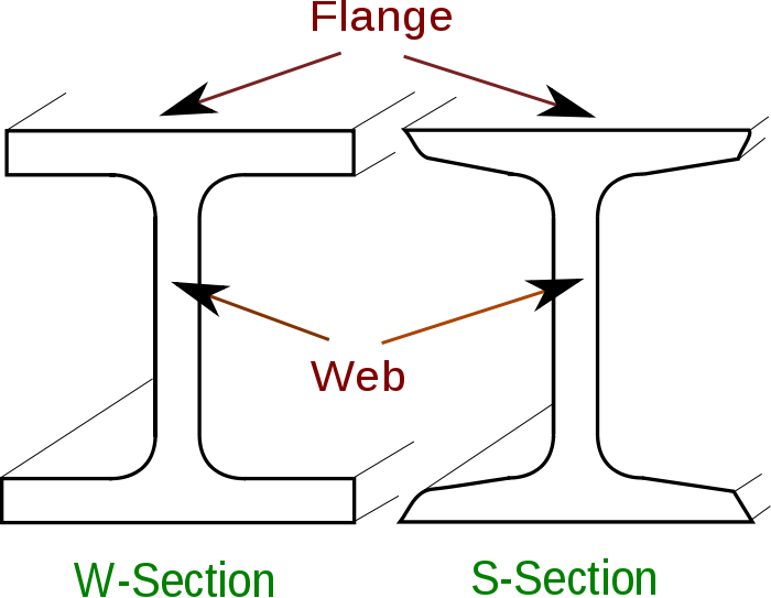
In terms of bending and stiffness the aim is to have as much of the material away from the neutral axis which is normally near to the center of the section. That is why "I" beams are very strong/efficient for the amount of steel they use. The flanges at the top and bottom of the section are what make these beams stiff. The object of the web is primarily to connect the two flanges and to keep them lined up - it comparison to the flanges the web contributes relatively little to stiffness as material in the web is closer to the center of the section. So the larger the flanges are and the further they are placed apart the stiffer (and more resistant to bending) the beam is (in that specific plane). However if you were to turn this beam on its side it's properties change completely and it becomes much less stiff if the same loads are applied. Originally Posted by BobWes
Hope that explanation helps a little... back to your specific question. In the 75mm section the 35mm top and bottom ("flanges") are further apart making this section stiffer in the vertical plane (as you have defined it - pulling it up or down). The 75mm sides ("webs") although larger and containing more material than the 35mm top and bottom contribute a relatively smaller amount to stiffness in this plane.


 Reply With Quote

Similar Threads
-
Goat Island Skiff vs Green Island 15
By ausie in forum BOAT DESIGNS / PLANSReplies: 26Last Post: 15th July 2021, 05:19 PM -
Goat Island Skiff
By bitingmidge in forum Michael Storer Wooden Boat PlansReplies: 513Last Post: 31st October 2019, 04:03 PM -
Goat Island Skiff
By woodeneye in forum CLASSIC BOAT RESCUE & ADOPTIONReplies: 2Last Post: 31st December 2011, 11:17 PM
Tags for this Thread
academy,
ann,
bend,
boom,
booms,
comfortable,
conditions,
construction,
cross-sections,
design,
dimensions,
goat,
happy,
island,
karen,
lug,
mph,
noticeable,
perfect,
possibly,
reef,
rig,
sailed,
search,
session,
skiff,
skills,
taper,
week,
winds
