

 Thanks: 0
 Likes: 0
 Needs Pictures: 0
 Picture(s) thanks: 0
Results 1 to 15 of 21
Thread: Adjusting Rino/MadCAM/Mach3?
-
5th March 2010, 07:16 PM #1
 SENIOR MEMBER


- Join Date
- Dec 2005
- Location
- Brisbane
- Age
- 53
- Posts
- 293
 Adjusting Rino/MadCAM/Mach3?
The CNC router is done, all axis are working fine. I'm trying to setup the whole shabang to cut somw timber. At this point, I'm not too sure what I need to fix; Mach3 or MadCAM...
1. I drew a 150mm diameter circle and used madCAM to post-process it, it looks fine in the simulation. Problem; the cnc is air cutting something that more like 50mm dia, any ideas?
2. Where are you supposed to adjust feed speeds?? mach3 or madCAM? The cnc is cutting pretty slowly, I need to pump the FRO to 250% to get a bit more speed but I want lots more, what do I do?
3. I'm confused about Z axis zero. when I prepare for a job do I have to zero the Z axis on the table or on the top of the workpiece?
Sorry for being a total newb
-
5th March 2010 07:16 PM # ADSGoogle Adsense Advertisement
- Join Date
- Always
- Location
- Advertising world
- Age
- 2010
- Posts
- Many
-
5th March 2010, 08:15 PM #2
SENIOR MEMBER
- Join Date
- May 2005
- Location
- Cockatoo Vic
- Posts
- 996
1. I drew a 150mm diameter circle and used madCAM to post-process it, it looks fine in the simulation. Problem; the cnc is air cutting something that more like 50mm dia, any ideas?
First thing to check will be steps per unit settings. This is set in Mach3
2. Where are you supposed to adjust feed speeds?? mach3 or madCAM? The cnc is cutting pretty slowly, I need to pump the FRO to 250% to get a bit more speed but I want lots more, what do I do?
Not familiar with Madcam but this is something you specify in the CAM program.
It may be in the tool selection part of setting up the toolpath.
Cutting feedrates are set in CAM and rapid speeds are set in Mach3.
3. I'm confused about Z axis zero. when I prepare for a job do I have to zero the Z axis on the table or on the top of the workpiece?
Again this will be a selection you make in the CAM program. For 90% of jobs I cut I select Z zero to be the top of material.
Greg
-
5th March 2010, 08:20 PM #3
GOLD MEMBER
- Join Date
- May 2003
- Location
- Perth WA
- Posts
- 3,784
Hi Phil,
Great you have finished the machine - post some photos.
You zero the Z axis on the top of your job (workpiece). If you haven't done the Greolt touchplate then make it a priority. Until then use a piece of fine paper between the end of you cutter and the job. Move you Z down slowly (better by manual movement than under power) and at the same time wiggle the paper back and forth until you feel it pinch the paper. Don't forget to zero the DRO on your screen. Power up and immediately move the Z to a safe height.
Feed rate is set in the gcode. So this will be done in Madcam and not having used this software I can't help you. Look in tool setting as a start.
Have you calibrated your machine in Mach3?
First make sure your native units are set to mm. Go to config and "select native units" to set that. Quickest way to calibrate is to go to the "Settings" button (on the top of the screen) and run through the "Set Steps per Unit" routine. Overview is you select axis to calibrate, tell it how far you want to travel, measure how far it has actually travelled and enter that value in Mach 3 then Mach3 will calibrate that axis.
Any more issues with your feed speed, etc can you post your gcode file and I'll have a look at it for you otherwise I am guessing and will just confuse us both.
Sorry Greg you think and type quicker than me so I have duplicated your post.Cheers,
Rod
-
5th March 2010, 08:43 PM #4
SENIOR MEMBER
- Join Date
- Dec 2005
- Location
- Brisbane
- Age
- 53
- Posts
- 293
I have both Mach and madCAM set in mm. I did go through all the Mach setup with the online video tutorials and have setup my table length and ballscrew travel too (calculations) once I entered it all in, I did check the distance with the auto-adjust travel. It's all good.
It makes no sense to me that the CNC isn't cutting at the right dimensions, I'm lost on that one.
I found the part in madCAM that does the travel speed and set it pretty high (2000units/min) Mach is only running at 300units/min in the FRO part of the main screen. I need to boost it to 250% to get 900mm/min, its still pertty slow compared to what the CNC can do when I test it + it gives me big red danger leds flashing, is this ok to do? Any idea why the speed is different in Mach and madCAM?
So here goes with the first few lines of code, maybe you can find something in there
thanks Rod and Greg!
(will post pics and a vid as soon as I get a large enough movement on the table )
)
O2
G40 G54 G80 G90
(FLAT_END_6)
M06 T1
S4000 F300 M03
G43 H1
G00 X33.18493 Y28.21974
Z8.01000
G01 Z4.17973 F300
X33.44825 Y27.95635 Z3.80729 F300
X33.79045 Y27.62843 Z3.33333
X34.13973 Y27.30808
X34.49902 Y26.99248
X34.86823 Y26.68214
X35.24728 Y26.37749
X35.63612 Y26.07894
etc....
-
5th March 2010, 09:00 PM #5
GOLD MEMBER
- Join Date
- May 2003
- Location
- Perth WA
- Posts
- 3,784
Hi Phil
If you have a look at line 5 you can see the feed rate is 300mm/min
The F300 is the feed rate.
You can edit this in Mach3 by pressing the "Edit G-Code" button and doing a find/replace and substituting another value in there. Quite often the feed rate is repeated in the GCode so just changing the first one you see does not fix it.
Save the file and exit and you will return to Mach3.
If you want to attach the whole file I'll run it here and see what diameter it is getting.Cheers,
Rod
-
5th March 2010, 09:05 PM #6
SENIOR MEMBER
- Join Date
- Dec 2005
- Location
- Brisbane
- Age
- 53
- Posts
- 293
Cool thanks!
Also, I just drew a 3D circle in Rhino, 150mm diameter 5mm height, I just programmed one pass (2.5D profile) to cut the whole 5 mm thickness in one pass. The simulator shows me just that but Mach3 runs 3 passes at different heights
O2
G40 G54 G80 G90
(FLAT_END_6)
M06 T1
S4000 F300 M03
blah blah blah
X33.79045 Y27.62843
G00 Z4.00500
G00 Z8.01000
M09
M30
-
5th March 2010, 09:19 PM #7
GOLD MEMBER
- Join Date
- May 2003
- Location
- Perth WA
- Posts
- 3,784
The code is only doing around 50mm circle and certainly not 150mm.
Mach3 is behaving well here and all these issues are from your cam package so concentrate there.
Perhaps some system settings or the post processor in Madcam are overriding what you are doing. Sorry but I have not even seen Madcam so difficult to help you here.Cheers,
Rod
-
5th March 2010, 09:26 PM #8
SENIOR MEMBER
- Join Date
- Dec 2005
- Location
- Brisbane
- Age
- 53
- Posts
- 293
Ok, I managed to fix some of the problems. For some reason madCAM seemed to find it complicated to program something 150mm diameter because I had selected the Rhino "small mm" template. I tried again in "large mm" template and got what I needed. I program the speed in MadCAM but for some reason it always gives me 300u/min, at least thanks to you now I can fix it easily by editing.
I'm finally geting somewhere, I just drew my first CNC circle on a piece of paper, video to follow shortly. My other madCAM questions will probably be better off in their own forum thanks!
-
5th March 2010, 09:47 PM #9
SENIOR MEMBER
- Join Date
- Dec 2005
- Location
- Brisbane
- Age
- 53
- Posts
- 293
[ame=http://www.youtube.com/watch?v=1-JQl-pD4h8]YouTube - Homemade CNC Router[/ame]
-
5th March 2010, 09:50 PM #10
GOLD MEMBER
- Join Date
- May 2003
- Location
- Perth WA
- Posts
- 3,784
Wohooo
I hope you have a silly grin on your face for a week.Cheers,
Rod
-
5th March 2010, 09:56 PM #11
SENIOR MEMBER
- Join Date
- Dec 2005
- Location
- Brisbane
- Age
- 53
- Posts
- 293
I'll definitely have it until tomorrow morning. Whether I still have that grin by the end of the week-end will be solely based on if I can cut timber without destroying
If I can start pumping out parts for my instruments by then I'll be a VERY happy camper.
-
6th March 2010, 08:00 PM #12
SENIOR MEMBER
- Join Date
- Dec 2005
- Location
- Brisbane
- Age
- 53
- Posts
- 293
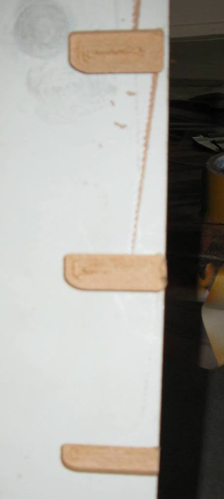
Problem again, the CNC is programmed to cut rectangles. If I check out the g-code, its programmed to cut rectangles yet I get this when I mill it. One of the corners on one side is always rounded. What could be the cause of this? Could this be a problem with my table?
-
6th March 2010, 11:16 PM #13
GOLD MEMBER
- Join Date
- May 2003
- Location
- Perth WA
- Posts
- 3,784
Hi Phil,
No it is most unlikely to be a problem with your table.
My guess is you have constant velocity on in Mach3. Change this to exact stop in config menu and run the job again. That should fix it if your gcode is right.
If not it could still be your cam software so if you like to attach your code I can have a look at it. Just attach as a file rather than post it in the thread - zip it if needs be. If you can't work out how to do that then PM me with the code in the main body of the email.
Greg is the best person to describe constant velocity and how to tune it to get best performance verses compromises in cutting corners.Cheers,
Rod
-
6th March 2010, 11:35 PM #14
SENIOR MEMBER
- Join Date
- Dec 2005
- Location
- Brisbane
- Age
- 53
- Posts
- 293
I sure hope that's the problem. I adjusted it in mach, I'll find out tomorrow morning if that works. I had a look at the G-code and it looks normal. I brushed up on a lot of that stuff today, spent from 9am to 8pm in front of that computer and CNC. I'm pretty happy I took a basic CNC/cam programming class last year, that was handy.
I've been running the job at 1600mm/min is that a good speed or could that also cause problems if its too fast?
-
6th March 2010, 11:55 PM #15
GOLD MEMBER
- Join Date
- May 2003
- Location
- Perth WA
- Posts
- 3,784
I had a look at your video on the other thread and if they are the same pockets you are cutting then it is not backlash. Backlash is usually small variations and to generate a curve like that you would be able to move an axis and feel it in the mechanicals easily.
It is not missiing steps as you are doing multiple passes (depth) over the same shape and it is cutting the same area each time. So I am alomst certain that it is not your machine.
Try the exact stop to eliminate Mach3 but gut feeling is it is your code from your cam package.
Can you send me the dxf file and depth of cut, tool diameter and feed speed and I will generate some code so you try it on your machine or at least compare to your code.
I can get it back to you before tomorrow so you can play while I am sleeping - 3 hours time difference.Cheers,
Rod


 Reply With Quote
Similar Threads
-
C11G , Geckos ,Mach3 problem
By wjfiles in forum CNC MachinesReplies: 1Last Post: 14th December 2009, 03:52 PM -
Mach3 license
By chrisb691 in forum CNC MachinesReplies: 5Last Post: 21st October 2008, 07:12 PM -
Mach3 setup
By chrisb691 in forum CNC MachinesReplies: 5Last Post: 21st October 2008, 01:39 PM -
Adjusting a Set Square
By newtowood in forum WOODWORK - GENERALReplies: 1Last Post: 28th January 2007, 03:11 PM -
Help adjusting the blade to zero
By FlyingDuck in forum TRITON / GMCReplies: 13Last Post: 29th June 2005, 10:32 AM
