

 Thanks:
  Likes:
  Needs Pictures:
  Picture(s) thanks:
Results 136 to 150 of 336
Thread: G540 & CNC Build
-
28th September 2010, 08:45 PM #136
 GOLD MEMBER


- Join Date
- May 2003
- Location
- Perth WA
- Posts
- 3,784

A datum is a point that everything is measured back to - a zero reference.
If you set up your table in the upper position fix a plate or piece of angle iron on all four legs flush with the top of the table. This is your datum and all you need now is a gauge rod for each position of the table below that. Place the gauge rod up to the datum and set the new position of the table to the length of the gauge rod on all four corners. Different length gauge rods for each height setting.
I like the mounts - that was a tight squeeze for the Z axis end bearing.Cheers,
Rod
-
28th September 2010 08:45 PM # ADSGoogle Adsense Advertisement
- Join Date
- Always
- Location
- Advertising world
- Posts
- Many
-
28th September 2010, 11:33 PM #137
Senior Member
- Join Date
- May 2008
- Location
- Geelong
- Posts
- 264
OK... sounds like a good idea. I'll use the rails on the legs and most likely use angle line for the base.
Where do you get your cable protectors from? The plastic track the wires run in? lol... what's the stuff called?
Brad.
-
29th September 2010, 12:03 AM #138
GOLD MEMBER
- Join Date
- May 2003
- Location
- Perth WA
- Posts
- 3,784
You will still need a winder of some sort as I imagine that table to be heavy. Perhaps shift your datum to the bottom of the legs so it can rest on the gauge rod. I'm sure you will work it out. With the length of your Z axis I would imagine you only need two positions. If you can get the play out of Z then you really only need the bottom position.
Not sure what you mean about cable protectors.
I use a lot of clear spiral wrap inside the cabinet. Ausxmods sells the stuff I use - it is 6mm but will open up to just about any size. Chirs is great to deal with and I hope he gets support from this forum.
Cable ducting has a U shape channel with a clip on cover. I use this inside the electrical enclosure and scrounge most of it up but have got the odd length from Bunnings.
Cable or energy Chain is the hinged box shape section that carries the wires to the motors. I get that from Chai at Linearmotionbearings2008.
I'm catching up to your build now and looking and thinking about similar things as you. Cheers,
Rod
-
29th September 2010, 02:13 AM #139
Senior Member
- Join Date
- May 2008
- Location
- Geelong
- Posts
- 264
Can the energy chain have links removed? I found a few different sellers seller various lengths.
Brad.
-
29th September 2010, 02:23 AM #140
GOLD MEMBER
- Join Date
- May 2003
- Location
- Perth WA
- Posts
- 3,784
All the ones I have got can be. You can also reverse the chain to create an "S" shape. Handy when you are changing direction. Look for a suitable radius bend for your machine - one that fits within your fixing points as well as not being too tight a radius for the wires to bend - eg your spindle wire may not have as tight a radius as your stepper motor wire so go for the larger radius for all.
I think I am making this sound more difficult than it is.
There is an Australian supplier that Greg has posted here a couple of times so do a search if you think this will help. It is not expensive stuff but it does make a huge difference to cable management.Cheers,
Rod
-
30th September 2010, 12:41 AM #141
Senior Member
- Join Date
- May 2008
- Location
- Geelong
- Posts
- 264
I tightend the Z-axis bearings today and the axis still has slight flex... Im thinking if I place some angle aluminium.. maybe 30mm x 30mm down the front on the Z-axis on the front plate in line with the inside rail mount holes..
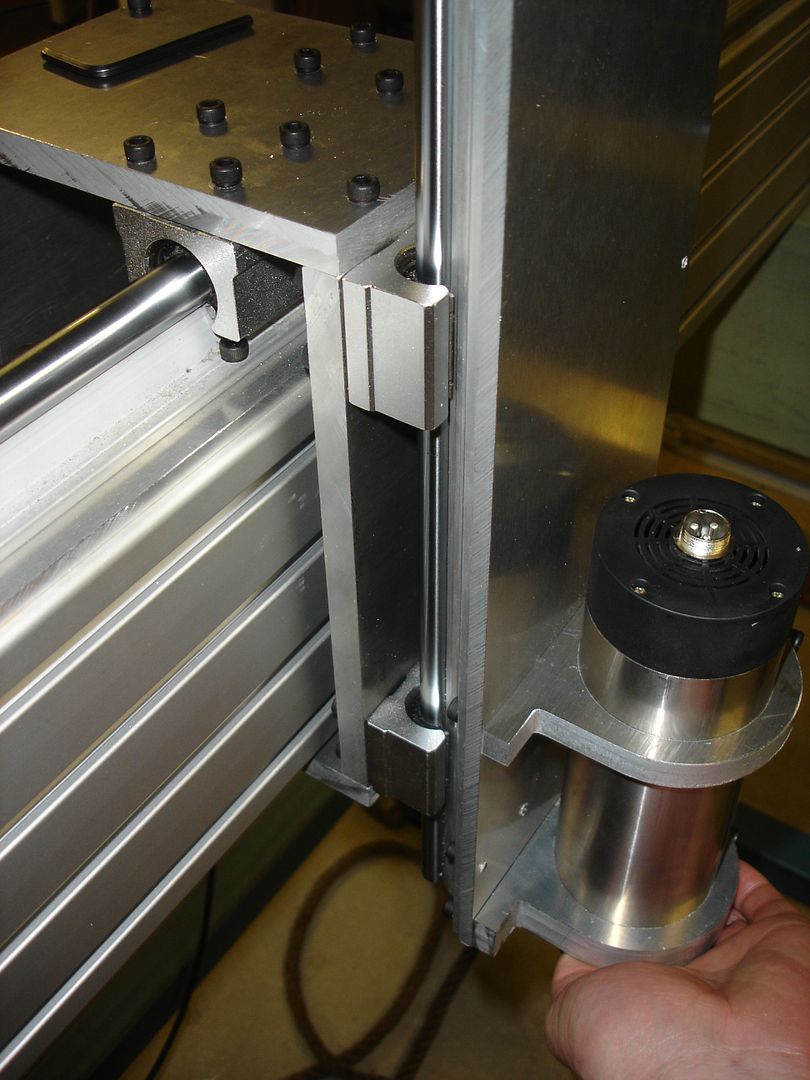
One length on each side it should provide a little more rigidity to the axis and allow a channel to run the spindle lead.
Brad.
-
30th September 2010, 02:03 AM #142
GOLD MEMBER
- Join Date
- May 2003
- Location
- Perth WA
- Posts
- 3,784
Hi Brad,
Find out where it is happening first. Clamp a straight edge (bit of angle will do) top and bottom and flex the plate. Stand side on with daylight or a light on the other side and look for gaps as you flex the Z axis. If a gap doesn't appear then it is probably the bearings. If there is flex in the plate then follow up with your idea of stiffeners.
Having played with the 12mm rails recently I suspect they are the cause.
To be brutally honest it is a big ask for round linear rails to do what you want on such a long overhang. You have a big lever there and the square rails and trucks would have delivered a better result.Cheers,
Rod
-
30th September 2010, 10:40 AM #143
Senior Member
- Join Date
- May 2008
- Location
- Geelong
- Posts
- 264
Yeah.. good idea to try clamp it first. I've still yet to check the tightness of the y and x bearings, so they might be contributing to the moment also.
I knew such a long axis was going to be an issue that's why I hadnt made the table fixed full depth first... but the sqaure rails being better for such a job I was unaware. Good info to know.
Brad.
-
30th September 2010, 12:16 PM #144
Senior Member
- Join Date
- May 2008
- Location
- Geelong
- Posts
- 264
Not a happy camper!!! The X axis was a little loose.. easy to tighten.. but the Y-axis bearings are very sloppy and there's no way I can see to adjust them. Even when the Z-axis is raised to a normal height this machine wont work with this slop!!! Does anyone here own 16mm rails and bearings that can be adjusted? Or did I just happen to buy a ###### set of 4 blocks?
I think I'll be sending Chai an email.
lol... hey it's censored me..hehehe.
Brad.
-
30th September 2010, 12:24 PM #145
GOLD MEMBER
- Join Date
- May 2003
- Location
- Perth WA
- Posts
- 3,784
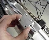
I am confident Chai will do the right thing so approach him with this in mind. I have 16mm rails on my machine I am building and they have a single grub screw in the top to adjust them - yours don't by the photo.
The joys of machine building.
###### - well that is stange I typed # and it didn't censor it. Cheers,
Rod
-
30th September 2010, 12:42 PM #146
Senior Member
- Join Date
- May 2008
- Location
- Geelong
- Posts
- 264
Ok... good to know. Mine are OLD stock. I bought them off Chai about 2 years ago when he was just starting up his business. I've just emailed him via his contact on Ebay so hopefully I'll get a good response.
Brad.
-
30th September 2010, 10:36 PM #147
Senior Member
- Join Date
- May 2008
- Location
- Geelong
- Posts
- 264
He is good... He's sending four replacements. He also couldnt understand why there was no adjustment holes.
Here's a pic I took back in 2008 when it all arrived.
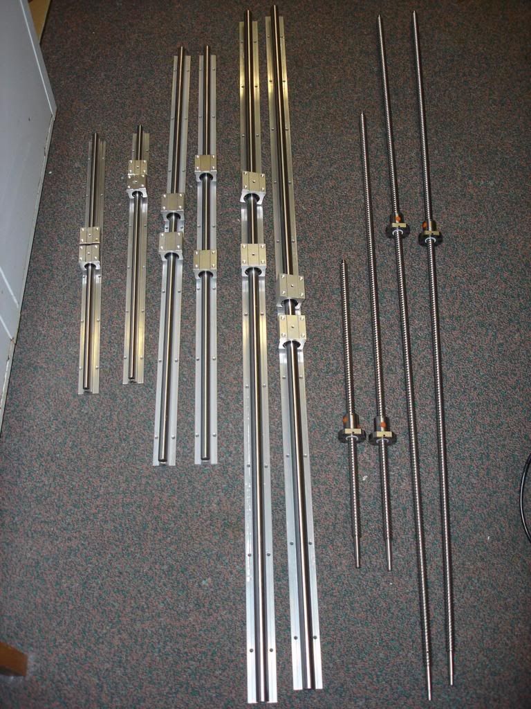
No adjustment holes in the 16mm bearing cases. Interestingly, on his website some of the pictures showing the 16mm bearings are also lacking in any adjustment holes. I'd say he's using old pitures.
Here's a video of the other two...
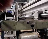
Same issue... one was perhaps a little tighter but still had slop.
So hopefully in a few weeks I'll have another look at stabilising the Z -axis.
Brad.
-
1st October 2010, 02:43 AM #148
GOLD MEMBER
- Join Date
- May 2003
- Location
- Perth WA
- Posts
- 3,784
Good to hear you got it sorted out.
Cheers,
Rod
-
1st October 2010, 04:48 PM #149
SENIOR MEMBER
- Join Date
- Feb 2008
- Location
- NOWRA
- Posts
- 648
What are you doing with the ones with slop???
Daniel
-
1st October 2010, 05:06 PM #150
Senior Member
- Join Date
- May 2008
- Location
- Geelong
- Posts
- 264
Funny you should ask.. as we speak I've pulled apart one of my spare 12mm bearing/pillow blocks to find out exactly what / how the grub screw functions... so far what I can tell is it just seems to apply presure to the back of the bearing housing and I'd be guessing pushes it slightly out of shape. So I've drilled and taped a hole in the 16mm pillow block and about to put the grub screw in it from the 12mm block... so in a few minutes I'll know if I've repaired one.
Brad.

 Reply With Quote
Similar Threads
-
Gecko G540 CNC Kits now available
By phomann in forum CNC MachinesReplies: 46Last Post: 17th January 2010, 06:25 PM -
G540 Matched Motors
By seafurymike in forum CNC MachinesReplies: 4Last Post: 25th September 2009, 02:47 PM -
Trailer - to build or not to build
By motegi in forum TRAILERS & OTHER FABRICATED STUFFReplies: 17Last Post: 6th May 2009, 03:07 PM -
Mach 3 & G540 Motor tuning
By seafurymike in forum CNC MachinesReplies: 13Last Post: 20th April 2009, 04:24 PM -
Gecko G540 - special offer
By snowyskiesau in forum CNC MachinesReplies: 13Last Post: 13th February 2009, 01:50 PM
