

 Thanks:
  Likes:
  Needs Pictures:
  Picture(s) thanks:
Results 166 to 180 of 336
Thread: G540 & CNC Build
-
6th October 2010, 10:38 PM #166
 GOLD MEMBER


- Join Date
- May 2003
- Location
- Perth WA
- Posts
- 3,784

As Chirs has said you can unclip it and create S bends to change direction. I take it as close as I can to the electrical enclosure which means I have better cable management - beats bundling and cable ties and it offer protection for the cable. If you have a look at the last set of photos for BigG you can see what I have done.
Cheers,
Rod
-
6th October 2010 10:38 PM # ADSGoogle Adsense Advertisement
- Join Date
- Always
- Location
- Advertising world
- Posts
- Many
-
8th October 2010, 12:25 AM #167
Senior Member
- Join Date
- May 2008
- Location
- Geelong
- Posts
- 264
Nice.. if I need to feed it back the other direction I just flip the chain.
 Not sure what Im doing with the excess chain, but if I decide to off load it I'll offer it here first.
Brad.
-
10th October 2010, 12:09 AM #168
Senior Member
- Join Date
- May 2008
- Location
- Geelong
- Posts
- 264
I've been thinking about a worm drive for a 4th axis. What have others used? And where to get one? Ebay? The depth of my Z axis might allow a verticle 4th axis.
Brad.
-
10th October 2010, 12:38 AM #169
SENIOR MEMBER
- Join Date
- Feb 2008
- Location
- NOWRA
- Posts
- 648
Worm drives work great and a second worm drive can be added with a spring setup to remove backlash. I have AT5 timing belts on mine. Really like the looks of planetary gearboxes but price is up there and removes the possibility of a thru bore for stock.
Height wise, i think you might need to look at raising your gantry...lol. I've been thinking though, as i had a smaller gantry on first machine, how nice those wooden plates are done and thought how nice it would be to have a horizontal (turntable) rotary in the table which might make bowls and plates easier. Food for thought for anyone with a low clearance gantry.
Daniel
-
10th October 2010, 02:11 PM #170
Senior Member
- Join Date
- May 2008
- Location
- Geelong
- Posts
- 264
The clearance between my table and gantry will be about 550mm so im not sure why i'd have to raise it?
eBay Australia Store: Search results for MOTIONTEK CANADA.
I found the gear boxes you're referring too..but not sure how two worm drives would work?
Brad.
-
10th October 2010, 05:12 PM #171
SENIOR MEMBER
- Join Date
- Feb 2008
- Location
- NOWRA
- Posts
- 648
The Gantry raiser was just a joke. The planetary gearboxes don't require worm drives. They are a special gear configuration to get high ratio reductions with minimal to no backlash. COnnect up either stepper or servo motor of the gearbox frame size and your ready. This multiplies your torque alot and gets you very high resolution. As for two worm drives. One is driven by the stepper/servo and the second is on a spring setup to push against the gear mesh (much like the pre-load of a dual ballnut setup) to remove any backlash.
Daniel
-
10th October 2010, 06:42 PM #172
Senior Member
- Join Date
- May 2008
- Location
- Geelong
- Posts
- 264
 Sometime they just go staight over my head..
  There should a joke text!!
I figure if I can rotate my spindle 90 degrees and place verticle rotary wheel in my table I'll have a workable 4th axis....AND... if I had the rotation of the spindle on an axis!!!! A 5th Axis!!!! LOL... I wish.
Perhaps I just get the 3 axis working first.
Brad.
-
19th October 2010, 11:34 PM #173
Senior Member
- Join Date
- May 2008
- Location
- Geelong
- Posts
- 264
Some general info.... If you own a Kress and it does this.

try fix it with the cheaper option first. At first you might think it's the variable speed control... and get one of these...
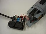
Only to find... nope.. still not working properly. Then you'd need to get part No.16.
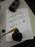
It lives deep inside the Kress at the very top of the motor in a plastic casing. The Magnet ring!! Why didnt I think of that the first time!!!... so I ordered 3... at $2.80 per ring I thought I'd get some spare.
So when they arrive, hopefully this time it'll work.
Brad.
-
20th October 2010, 11:45 PM #174
Senior Member
- Join Date
- May 2008
- Location
- Geelong
- Posts
- 264
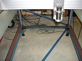
Started on the table over the weekend and did some more today. It seems to track up and down the rails on the legs. I needed a person at each end to lift in unison. Now I've another 5 lengths of steel to attach, then the table top. This machine is going to be HEAVY!!! Also added so extra bracing to remove any chance of the frame twisting.
Brad.
-
23rd October 2010, 11:29 PM #175
Senior Member
- Join Date
- May 2008
- Location
- Geelong
- Posts
- 264
Built the table and wound it up.
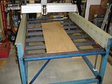
Took FOREVER to wind each allthread a few turns at a time by hand. I found these guys online...
Crest Manufacturing Industries Home
Might get some sprockets, chain, DC motor and controller from them to wind this table up and down. Still need to work out how Im going to lock it in place
Brad.
-
25th October 2010, 12:31 AM #176
Senior Member
- Join Date
- May 2008
- Location
- Geelong
- Posts
- 264
Anyone here runing a spindle connected straight to the G540? I've wired up the G540 to the spindle, hit the spindle button and my grinder turns on, not the spindle.
I've grabbed Bob's pic here...
My spindle control is set as this pic shows..

Mine says 14 in the step pin # as Mike has written in his guide.


My enable1 is set to off and my Output #1 is port 1 pin 17... is this the problem?
Mike guide didnt cover this Mack3 page.
Any ideas????
Tried PD001 at both 1 and 0, and PD002 at 1. If I return the VFD back to manual control it turns on just fine..manually.
Brad.
-
25th October 2010, 11:19 AM #177
Senior Member
- Join Date
- May 2008
- Location
- Geelong
- Posts
- 264
Another 2hrs spent working on this with nothing to show. I did find that the VFD puts put 9.92v across V10 and VI and when I tell Mach3 I want 12000rmp it drops to about 1/2 that. So is Mach3 working correctly and the VFD not? Anyone? Open to any ideas here!!!!
Brad.
-
25th October 2010, 11:42 AM #178
GOLD MEMBER
- Join Date
- May 2003
- Location
- Perth WA
- Posts
- 3,784
Hi Brad,
These setting from Bob's instructions are important. I had a similar problem with the DC06 and when I set all of the following it worked. I may have changed a couple of settings from Bob's in the table below.
You also need to fiddle with the Spindle motor tuning to get a match to your VFD.
Mine was 800 steps, velocity 1250 and acceleration 487. The velocity will determine your max and min speed.
Also set up a pulley to get 7200 min and 24000 max.
Point here is that the DC06 is an analogue voltage control and not PMW like Bob's unit.
I am probably the last person you want electronics advice from but failing any other responses take you chances with this.
000PD numberSet to numberUsed for
0
Parameter lock
001
1
Source of commands
002
1
Source of operating frequency (Sped control source)
003
400
Main frequency
004
400
Base frequency
005
400
Maximum operating frequency
006
2.5
Intermediate frequency
008
220
Maximum voltage
009
15
Intermediate voltage
010
8
Minimum voltage
011
120
Frequency lower limit
027
3
Starting frequency
028
3
Stopping frequency
070
0
Set control voltage to 0 - 105v (see note)
072
400
Lower analog frequency bias
141
220
Rated motor voltage
142
7
Rated motor current
143
2
Number of motor poles
144
3000
Rated motor revolutionsCheers,
Rod
-
25th October 2010, 11:44 AM #179
GOLD MEMBER
- Join Date
- May 2003
- Location
- Perth WA
- Posts
- 3,784
Sorry table came out crappy.
First line PD number,
Second line setting
Third line description of PD settingCheers,
Rod
-
25th October 2010, 12:00 PM #180
Senior Member
- Join Date
- May 2008
- Location
- Geelong
- Posts
- 264
I'll double check the numbers... one other weird thing .. when I set the revolutions to 24000 in Mach3 the voltage over v10 and vi drops to almost nothing. This seems to be in reverse?? and the lower I set the revolutions the higher the voltage?
Brad.

 Reply With Quote


Similar Threads
-
Gecko G540 CNC Kits now available
By phomann in forum CNC MachinesReplies: 46Last Post: 17th January 2010, 06:25 PM -
G540 Matched Motors
By seafurymike in forum CNC MachinesReplies: 4Last Post: 25th September 2009, 02:47 PM -
Trailer - to build or not to build
By motegi in forum TRAILERS & OTHER FABRICATED STUFFReplies: 17Last Post: 6th May 2009, 03:07 PM -
Mach 3 & G540 Motor tuning
By seafurymike in forum CNC MachinesReplies: 13Last Post: 20th April 2009, 04:24 PM -
Gecko G540 - special offer
By snowyskiesau in forum CNC MachinesReplies: 13Last Post: 13th February 2009, 01:50 PM
