

 Thanks:
  Likes:
  Needs Pictures:
  Picture(s) thanks:
Results 301 to 315 of 336
Thread: G540 & CNC Build
-
26th January 2011, 05:44 PM #301
 GOLD MEMBER


- Join Date
- May 2003
- Location
- Perth WA
- Posts
- 3,784

Brad,
Don't get hung up on resolution. Your steppers can only hold half steps anyway so the extra resolution is wasted - well not really as it helps round off numbers more accurately. Don't forget this will impact on the computer CPU sending down so many pulses just for one axis.
The other issue is speed. Work out your max speed of the stepper and I think you will find the 4th axis will be painfully slow with the extra reduction. You are not making space ships so I would run with a direct couple first up and you still have good resolution at 100/1. I think you will find that slow for the type of work you do and you may actually step that up in the future.Cheers,
Rod
-
26th January 2011 05:44 PM # ADSGoogle Adsense Advertisement
- Join Date
- Always
- Location
- Advertising world
- Posts
- Many
-
26th January 2011, 08:34 PM #302
Senior Member
- Join Date
- May 2008
- Location
- Geelong
- Posts
- 264
So telling Mach3 555.555555556 steps per degree wont be a problem?
If so, I could just rig up this sort of thing.
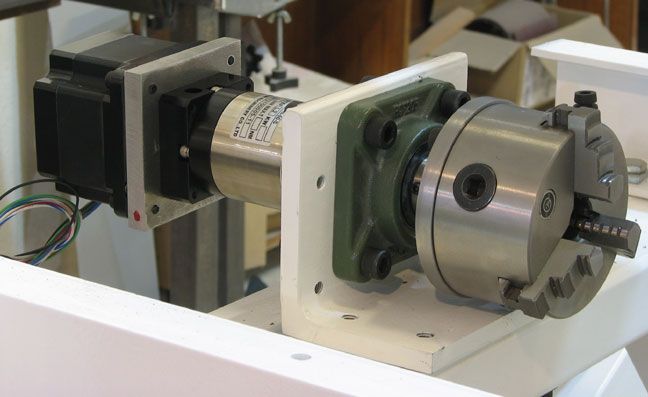
From a build on the MechMate board. I just noticed he's only using a 20:1 gear box.
Brad.
-
27th January 2011, 05:48 PM #303
Senior Member
- Join Date
- May 2008
- Location
- Geelong
- Posts
- 264
Im not sure what you mean by the steppers only hold 1/2 steps? It'll only accept 555.5 steps? So if it needs to do a 360 turn... 555.5 * 360 = 199980 steps but this is short of the 200000 needed for 360 degress with the 100:1 gear?
Brad.
-
27th January 2011, 07:52 PM #304
GOLD MEMBER
- Join Date
- May 2003
- Location
- Perth WA
- Posts
- 3,784
Hi Brad,
It is an electrical/mechanical limitation of a stepper - it can only hold the midway point between two coils. Don't confuse this with software setting.
Go into "Settings" screen in mach3 and do a "Calibrate Axis" for A axis and just pick any random numbers for this. This will return (hopefully) lots of decimal places and from now on you will be able to set to those deciaml places in Motor Tuning. Just a quirck of Mach3.Cheers,
Rod
-
27th January 2011, 10:13 PM #305
SENIOR MEMBER
- Join Date
- Nov 2006
- Location
- Darwin HowardSprings
- Age
- 52
- Posts
- 1,197
ill have a go at explaining it ,
when you energize coil "A' it jumps to "A" position and holds it self there at full torque
when you energize coil "B" it jumps to "B" position and holds its self there , at full torque
1/2 stepping is when both "A" and "B" are energized and the motor jumps to 1/2 way between "A and B " since both magnets want to go there separate ways , the holding torque is only 1/2 of the full holding torque
micro stepping , is turning a square wave ( rough running at low speed ) into a multi square stepped sine wave , so is going a,A,a,ab,AB,ab,b,B,b , if you stop at any of the micro steps , the hold position is still at a Full "A" , "B" or at half step "AB" ,
hope that helped , ken
-
31st January 2011, 11:59 PM #306
Senior Member
- Join Date
- May 2008
- Location
- Geelong
- Posts
- 264
Thanks Ken. Makes perfect sense. So I'll go the direct hook up. Here's what Im thinking.
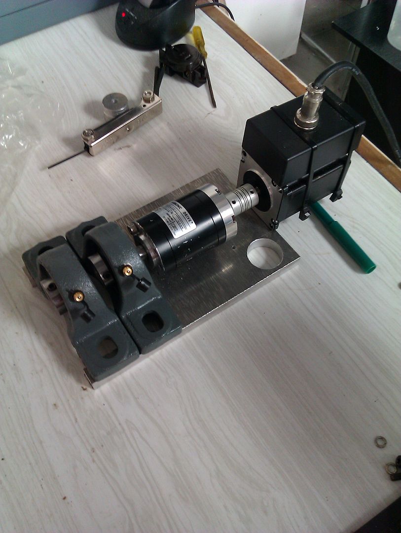
I did like the design above but it only seems to have one set of bearings supporting the shaft if the tail stock isnt in play. The second set of bearings on mine should keep the shaft level and ensure the only forces on the harmonic drive bearings will be rotational.
Brad.
-
1st February 2011, 01:22 AM #307
GOLD MEMBER
- Join Date
- May 2003
- Location
- Perth WA
- Posts
- 3,784
The correct approach is to have a tapered roller bearing like on the front axle of a car.
A chuck has radial as well as end forces and the tapered roller bearing is the cheapest option for that.
Pillow blocks are great for self allignment but not much chop for end loads.Cheers,
Rod
-
16th February 2011, 03:53 PM #308
Senior Member
- Join Date
- May 2008
- Location
- Geelong
- Posts
- 264
It seems to work.
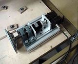
Brad.
-
20th February 2011, 06:26 PM #309
Senior Member
- Join Date
- May 2008
- Location
- Geelong
- Posts
- 264
Test run was OK... lost a few steps as I had it set in Mach too fast. The video shows it running at 30% speed, but I think it still tried to go too fast every once and while. I'm just doing an air cut as write this and it seems to be going ok.
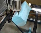
Didnt bother with the finish cut after it lost steps.
Brad.
-
20th February 2011, 07:26 PM #310
Senior Member
- Join Date
- May 2008
- Location
- Geelong
- Posts
- 264
I have a Xylotex contoller that Im hoping to use for control of the 4th axis. At the moment I have to use one of the contollers of the X-axis from the G540. Only I'll need to install a second parallel ports. Has anyone tried the motion control over two LTP ports? Can Mach do it?
Brad.
-
20th February 2011, 11:43 PM #311
GOLD MEMBER
- Join Date
- May 2003
- Location
- Perth WA
- Posts
- 3,784
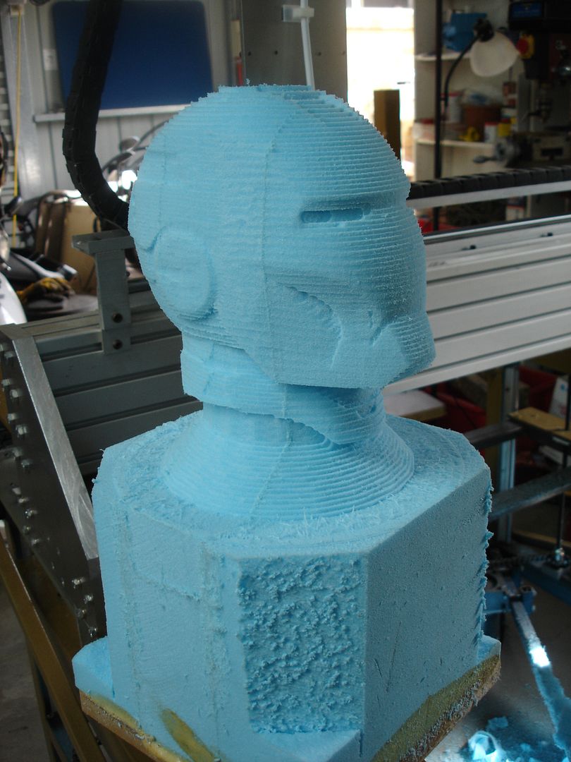
Hi Brad,
Love the work - the materials looks like timber but going by the colour it is machinable wax. It must have strands embedded in it to produce the fluffy stuff.
Mach3 allows two parallel ports and they will operate seamlessly. I have had two working on a machine (Motherboard and a PCI parallel port). The PCI address was tricky to find but I am sure you will work it out and it might be different with various brands of cards.
Alternatively you can go smoothstepper that already has two parallel ports on them.Cheers,
Rod
-
20th February 2011, 11:52 PM #312
Senior Member
- Join Date
- May 2008
- Location
- Geelong
- Posts
- 264
Hi Rod,
It's actually foam, I'll get another LPT card tomorrow and try it with the Xylotex controller. Just need to figure out how to disengage two of the axis as I've heard the controllers will blow without a motor contected.
Brad.
-
21st February 2011, 12:07 AM #313
SENIOR MEMBER
- Join Date
- Feb 2008
- Location
- Australia
- Posts
- 988
This option I would consider a big hassle but here goes, there are 2 outputs that are unused in the G540 setup (Unless you have external devices attached to them) and you can power a fifth axis from those outputs,
The output pins on the G540 are limited to ~10Khz so it may be an issue, but I had a customer splice the BD25 cable and redirect the outputs to a G201X driver which from what he told me worked great.
-
21st February 2011, 12:08 AM #314
GOLD MEMBER
- Join Date
- May 2003
- Location
- Perth WA
- Posts
- 3,784
Hi Brad,
If you are talking about disabling the Xylotex drives then they do have an enable jumper for each drive. i would also adjust the pots for the disabled axes to 0 volts as a safety measure.Cheers,
Rod
-
21st February 2011, 12:11 AM #315
Senior Member
- Join Date
- May 2008
- Location
- Geelong
- Posts
- 264
Hey Chris
Yeah I''ve been chatting to Greg about this as an option, but I'd lose my spindle on/off and second relay control so I'll give the second LPT a go. Thanks for the input though.
Brad.

 Reply With Quote

Similar Threads
-
Gecko G540 CNC Kits now available
By phomann in forum CNC MachinesReplies: 46Last Post: 17th January 2010, 06:25 PM -
G540 Matched Motors
By seafurymike in forum CNC MachinesReplies: 4Last Post: 25th September 2009, 02:47 PM -
Trailer - to build or not to build
By motegi in forum TRAILERS & OTHER FABRICATED STUFFReplies: 17Last Post: 6th May 2009, 03:07 PM -
Mach 3 & G540 Motor tuning
By seafurymike in forum CNC MachinesReplies: 13Last Post: 20th April 2009, 04:24 PM -
Gecko G540 - special offer
By snowyskiesau in forum CNC MachinesReplies: 13Last Post: 13th February 2009, 01:50 PM
