

 Thanks:
  Likes:
  Needs Pictures:
  Picture(s) thanks:
Results 16 to 30 of 336
Thread: G540 & CNC Build
-
6th January 2010, 10:24 PM #16
 SENIOR MEMBER


- Join Date
- May 2005
- Location
- Cockatoo Vic
- Posts
- 996

Maybe monitor the voltage across the SSR input to see what happens to it when the router unexpectedly stops.
Greg
-
6th January 2010 10:24 PM # ADSGoogle Adsense Advertisement
- Join Date
- Always
- Location
- Advertising world
- Posts
- Many
-
7th January 2010, 09:52 AM #17
http://www.homanndesigns.com/store
- Join Date
- Dec 2008
- Location
- Melbourne
- Posts
- 269
Brad,
My guess, is that your 12V power supply is marginal. The resistors are probably 5%, the SSR contains a resistor as well.
From your calculations, your supply can theoretically supply 27mA and your SSR needs 25mA. This is too close.
What I think is happening is that after you run it a few times the components heat up slightly, their resistance lowers, a little more current flows and the SSR turns on.
The SSR can accept 32V input, so why not just use the 24Vdc ?
If you want to use your 12V supply, put another 2.7K resistor (or two) in parallel with the 2 you already have.
Cheers,
Peter.
-
7th January 2010, 08:38 PM #18
Senior Member
- Join Date
- May 2008
- Location
- Geelong
- Posts
- 264
The specs on the control voltage for the relay are 3-32VDC and Im supplying 12VDC from the 48VDC power supply using the 12V zener diode. I just added a 3rd 2.7k resistor in parallel with the other two 2.7k resistors. This lowers the resistance down to 900Ohms and allows 40mA current. But.. the same thing happened.
The LED on the relay flicks on for about 1 sec then turns off. It continued to flicker for a few secs then stops completely. I had the voltmeter across the relay and the voltage flicked between 12v and 0. So Im fairly certain the G540 is doing the switching.
I tried a few different things. Once the relay was responding properly, I turned off and on the laptop again. And the same problem occured even after the resistor had heated up. So this time, I turned off and on the laptop and let it sit for about 1 min. Then turned on the controller box and let it sit for about 1 min. And this time it worked fine first go.
I think the issue is with the laptop and voltage output when trying to run the relay too close to bootup of the laptop. Perhaps it's still performing background processes that effect the voltage output of the parallel port. But Im only guessing.
I'll try running the controller with my PC sometime, but for now I'll just let it warm-up first.
Thanks for your help guys.
Brad.
-
8th January 2010, 04:09 PM #19
http://www.homanndesigns.com/store
- Join Date
- Dec 2008
- Location
- Melbourne
- Posts
- 269
Hi Brad,
You know, it sounds like it may be the opto in the G540. Or the laptop.
Is it possible to try another G540? or a different computer (that may be easier)
Also, the G540 has 2 outputs. Could you try the other one?
Cheers,
Peter.
-
8th January 2010, 06:30 PM #20
Senior Member
- Join Date
- May 2008
- Location
- Geelong
- Posts
- 264
Hi Peter, Originally Posted by phomann

Now you've got me thinking about it again...
Different computer was easier... I think.. taking my main PC out to the workshop required unplugging 1000's of leads..lol.. at least it seemed that way.
Then I realised I didnt have mach3 working on this computer..Doh!! so I downloaded another copy.. set-up all the mach3 settings, restarted the computer and hit the spindle button..
&
&
&
&
it works fine. Didnt fault. I followed the exact same start sequence.. The laptop as I suspected was the problem. Dont you love a good story with a happy ending!!
I might invest in another PC for the workshop one of these days... might make for a good excuse to the wife to upgrade my main PC.
Brad.
-
8th January 2010, 08:51 PM #21
GOLD MEMBER
- Join Date
- May 2003
- Location
- Perth WA
- Posts
- 3,784
.......or you can run it through a smoothstepper and USB
Don't show the wife this post. Cheers,
Rod
-
8th January 2010, 08:57 PM #22
Senior Member
- Join Date
- May 2008
- Location
- Geelong
- Posts
- 264
Oh... the smooth stepper and USB sound like fun!! Is this what Peter has on the top of his aluminimum plate in his build above? Where can I get one? Are what's the $$ required?

Brad.
-
8th January 2010, 09:53 PM #23
GOLD MEMBER
- Join Date
- May 2003
- Location
- Perth WA
- Posts
- 3,784
-
9th January 2010, 09:08 AM #24
http://www.homanndesigns.com/store
- Join Date
- Dec 2008
- Location
- Melbourne
- Posts
- 269
Originally Posted by rodm
Hi Rod,
I'll have to get you on commission.
Cheers,
Peter.
-
11th January 2010, 11:03 PM #25
Senior Member
- Join Date
- May 2008
- Location
- Geelong
- Posts
- 264
I've started drawing up the CNC again. Im using 180 x 75 C section for the sides of the frame. Im now trying to work of the best way to attach the rails and lead screws.
I want the rails for the x-axis as close to gantry as possible while still being protected by the C-section.
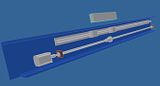
I'm looking for some advise on the distance the bearings on the X-axis should be spaced. The x-axis is rail are 1500mm and the y-axis will be 1000mm rails.
Brad.
-
13th January 2010, 09:47 AM #26
Senior Member
- Join Date
- May 2008
- Location
- Geelong
- Posts
- 264
Still looking for a little feedback. Let me put it another way... What's the distance between the bearings on the X & Y-axis of the machines you guys own.. those of you with X & Y rails about 1500mm x 1000mm.
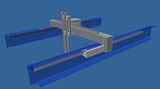
I've drawn up a little more. The gantry is going to be 80 x 80 extruded aluminimum 1200mm long. The Z-axis will be supported by 30x60 extruded aluminimun boxed around the gantry to give a stable edge for the bearings of the Z-axis. They'll be placed 250mm apart.
Brad.
-
13th January 2010, 09:59 AM #27
SENIOR MEMBER
- Join Date
- May 2005
- Location
- Cockatoo Vic
- Posts
- 996
In principal, as far apart as possible.
It depends on other factors. Height and rigidity of the gantry, expected performance, rigidity of the rail mounting and support. etc etc.
I know if I had 1500 long rails, I would be hoping to end up with 1200mm travel. Just because that is a common sheet size.
You should be able to attain that and keep them about 200 to 250mm apart.
Greg
-
13th January 2010, 11:43 AM #28
SENIOR MEMBER
- Join Date
- Feb 2008
- Location
- Australia
- Posts
- 988
I would upgrade the gantry to 120x80 or 160x80 as it has been proven a success on multiple builds.
If the C channel is steel do you plan on getting it machined?
-
13th January 2010, 08:16 PM #29
Senior Member
- Join Date
- May 2008
- Location
- Geelong
- Posts
- 264
Thanks Greg.. I'll work on 250mm on spacing for the X-axis bearings and see how that goes.
Nope.. no plan to get it milled yet. What's the problem with 80 x 80 for the gantry?
Brad.
-
13th January 2010, 08:46 PM #30
GOLD MEMBER
- Join Date
- May 2003
- Location
- Perth WA
- Posts
- 3,784
Hi Brad,
I'll chime in on that one. I see you are spanning 1200 with the 80 by 80 beam.
It is quite a large span so there is a chance of deflection in the beam along it's length. Remembering that when we use the machine we are working to surface depths of less than 0.1mm at times and any sag in the beam will be seen in the job.
The second reason is it places your linear rails closer together therefore the y axis is less rigid than a taller beam - not a biggy and you might find it is OK.
And last there is greater chance of twisting in a smaller sectional beam - probably unlikely but thought I would throw it in there anyway.
I would still run as you are with the 80 by 80 beam and see how it goes. It might be alright and only an engineer or somebody with a lot more grey matter than me would be able to calcualte the deflection.Cheers,
Rod

 Reply With Quote


Similar Threads
-
Gecko G540 CNC Kits now available
By phomann in forum CNC MachinesReplies: 46Last Post: 17th January 2010, 06:25 PM -
G540 Matched Motors
By seafurymike in forum CNC MachinesReplies: 4Last Post: 25th September 2009, 02:47 PM -
Trailer - to build or not to build
By motegi in forum TRAILERS & OTHER FABRICATED STUFFReplies: 17Last Post: 6th May 2009, 03:07 PM -
Mach 3 & G540 Motor tuning
By seafurymike in forum CNC MachinesReplies: 13Last Post: 20th April 2009, 04:24 PM -
Gecko G540 - special offer
By snowyskiesau in forum CNC MachinesReplies: 13Last Post: 13th February 2009, 01:50 PM
