

 Thanks:
  Likes:
  Needs Pictures:
  Picture(s) thanks:
Results 61 to 75 of 336
Thread: G540 & CNC Build
-
12th August 2010, 09:04 PM #61
 GOLD MEMBER


- Join Date
- May 2003
- Location
- Perth WA
- Posts
- 3,784

Hi Brad,
Been watching and it is coming along nicely.
You might consider mounting your rails on a plate then attaching the plate to the beam with T nuts. With a bit of thought in positioning the rail you should be able to tap the rails into the plate and then attach the plate to the beam with T nuts. This will give you a little play to align things.
If you are stuck on square rails then for LM series rails I went to Chai (Linearmotionbearings2008) and he helped out. I have to say Chai has given me great service and is very honest to deal with.Cheers,
Rod
-
12th August 2010 09:04 PM # ADSGoogle Adsense Advertisement
- Join Date
- Always
- Location
- Advertising world
- Posts
- Many
-
13th August 2010, 09:40 PM #62
Senior Member
- Join Date
- May 2008
- Location
- Geelong
- Posts
- 264
Hi Rod,
Yeah.. I was thinking about that but Im trying the keep the weight as low as possible. Perhaps I'll do this first and look at changing them at a later date, once up and running.
Today a length 500mm x 250mm x 20mm aluminium plate arrived with a 1/2 length of 80 x 80 x 6mm angle. So once my aluminium cutting blades for the drop saw and circ saw arrive I'll be ready to start cutting. In the mean time I'll drill maybe three holes in the C-section for each rail, just to hold them in place. And get the C-section mounted on the legs.
I did swap the C-section over and now have two straight lengths. Thanks Bluescope
I purchased a 10mm 1m pitch die and had a go at putting some thread on the ballscrew.... but it just wasnt going to happen, so I thought I'd get it done at a engineering place. I sent them an email asking for a quote to put 8 to 10mm of thread on four ballscrews with this picture...
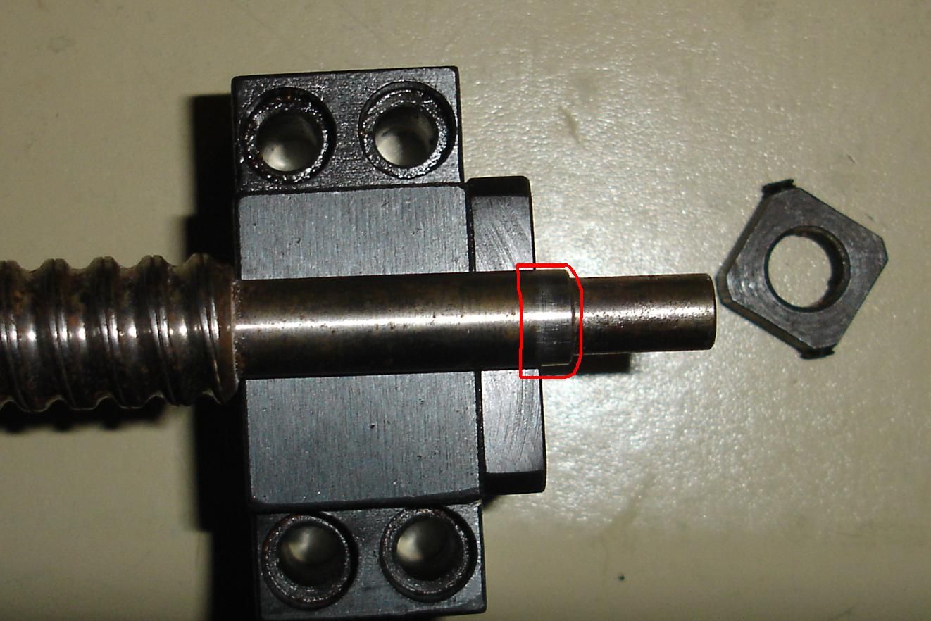
He replies saying $100.... so im thinking.... OK.. sounds a little expensive, not having used an engineering place before. And when I get there... he said.. OH,, I thought there was only one... and I nearly fell over... what $100 for 8mm of thread on 1 shaft... you've got to be kidding.. my email clearly stated 4. So he said to leave them with him but im thinking he's not going to do the job. In my shock over the price I didnt ask how long he'd need so emailed him the following day.. Thursday, asking for an estimate on time frame... I've still no response. Any wonder everyones getting work done in China... they hardly speak English and yet still give better service... go figure.
Brad.
-
13th August 2010, 09:58 PM #63
GOLD MEMBER
- Join Date
- May 2003
- Location
- Perth WA
- Posts
- 3,784
Any wonder everyones getting work done in China
It is a common theme and unless Aus wakes up the world is a small shopping village we will see more go overseas. I think engineering has been spoilt by the mining booms and big profits. Mind you the bloke knows he will probably never see you again so has priced accordingly - doesn't justufy it but explains it.
If it falls through then ask on the Ubeaut Metalworking forum and I'm sure there will be somebody there that can help especially if you have the die. They are very helpful over there.Cheers,
Rod
-
13th August 2010, 10:05 PM #64
Senior Member
- Join Date
- May 2008
- Location
- Geelong
- Posts
- 264
Oh... he'll see me again when I go to collect my property I've entrusted in his care.. and I've already requested another quote from another business. LOL... but that was also on Thursday with still no reponse.

Brad.
-
14th August 2010, 07:44 PM #65
Senior Member
- Join Date
- May 2008
- Location
- Geelong
- Posts
- 264
Cut the four parts out of the C-section. Need to take a small section from the top of the legs now, so the C-section can bolt in tight.
Also discovered my floor isnt real level.
Brad.
-
16th August 2010, 12:14 AM #66
Senior Member
- Join Date
- May 2008
- Location
- Geelong
- Posts
- 264
This thread pretty much answered all my questions on spindles...
https://www.woodworkforums.com/f170/w...pplier-118073/
So Im thinking this spindle should do the job.
NEW AIR-COOLE MOTOR SPINDLE 1.5KW AND MATCHING INVERTER - eBay Drives Motion Control, Industrial Automation, Control, Electrical Test Equipment, Business Industrial. (end time 28-Aug-10 01:05:30 AEST)
How are they wired into the G540? I take it from Peter's drawing there's a 3 plugs / pins / output / inputs on the VFD to contect it to the G540 when wired for a spindle? So you just leave the VFD on full and control it via Mack3?
http://www.homanndesigns.com/EN010_V8.pdf
Brad.
-
16th August 2010, 12:36 AM #67
GOLD MEMBER
- Join Date
- May 2003
- Location
- Perth WA
- Posts
- 3,784
Hi Brad,
Read through this thread as it will tell you what not to do as well as the correct way to do it. Air spindles have to start at 100hz to provide enough cooling.
https://www.woodworkforums.com/f170/t...d-users-96380/
Mike has a very good document at the end of the thread that shows exactly how to hook up the Mach controls to the G540.
I just wired up my Huanyang VFD today and I have a feeling Peter's schematic is wrong. He has the single phase going to R and S and all the data I have says R and T. I will check with Peter as I would not pitch my knowledge against Peter's but it does show you need to double check everything in this game. I'll report back here with his response.
BTW are you aware the 1.5kw spindle will only hold a 1/4 inch bit due to the ER11 collet. This is no problem for me but it might be for you.Cheers,
Rod
-
16th August 2010, 01:25 AM #68
Senior Member
- Join Date
- May 2008
- Location
- Geelong
- Posts
- 264
Cripes!!! After reading through most of that I'm just about too nervous to purchase one.

But it sounds if I get stuck / confused, which Im sure I will someone here will have the anwsers. Thanks for the thread Rod... even though it was a scary read.
Brad.
-
16th August 2010, 01:33 AM #69
GOLD MEMBER
- Join Date
- May 2003
- Location
- Perth WA
- Posts
- 3,784
I was reading it again to try to work out if the incoming single phase was R and S or R and T. Seems like it doesn't matter as Noel had his to R and T and Mike had his to R and S. Actually the R and S connection was around the wrong way as well. So it might just rectify the incoming single phase so it doesn't matter.
I'll still ask Peter as I don't want to stuff up mine.Cheers,
Rod
-
16th August 2010, 12:40 PM #70
GOLD MEMBER
- Join Date
- May 2003
- Location
- Perth WA
- Posts
- 3,784
Peter said his drawing was generic and to follow the manual of your VFD.
Cheers,
Rod
-
16th August 2010, 02:08 PM #71
Senior Member
- Join Date
- May 2008
- Location
- Geelong
- Posts
- 264
Most of my work is with smaller bits then 1/4 inch so I've been using the end of a Proxxon grinder I burnt out.. It currently fits in my 6mm Kress collect.. and has a shaft of 6.1mm. I'm fairly sure the Kress 1/4" collet will also hold it in place. Do you think the ER11 pull in enough to hold it?
Brad.
-
16th August 2010, 05:15 PM #72
GOLD MEMBER
- Join Date
- May 2003
- Location
- Perth WA
- Posts
- 3,784
Hi Brad,
Just buy a set of ER11 collets for $30 from here a bit cheaper than your other collets.Cheers,
Rod
-
16th August 2010, 05:50 PM #73
Senior Member
- Join Date
- May 2008
- Location
- Geelong
- Posts
- 264
That works for me.
-
18th August 2010, 07:34 PM #74
Senior Member
- Join Date
- May 2008
- Location
- Geelong
- Posts
- 264
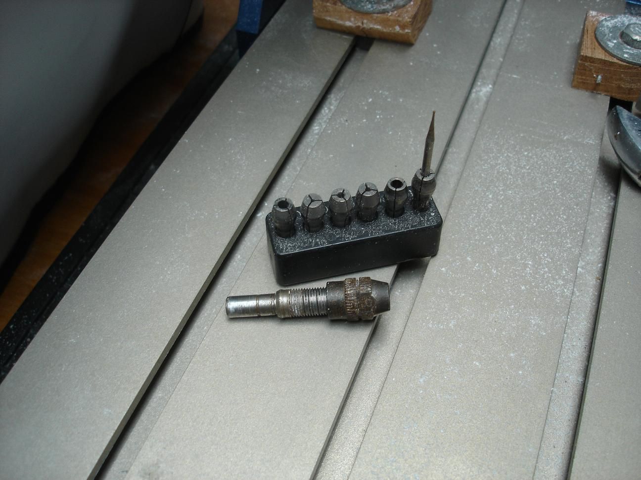
I picked up my ballscrews today.
 All done!! That second engineering company did get back to me with a quote for turning four threads onto the ballscrews .. $274.00 but luckly for me the guy that "misquoted" me from the first business was good to his word.
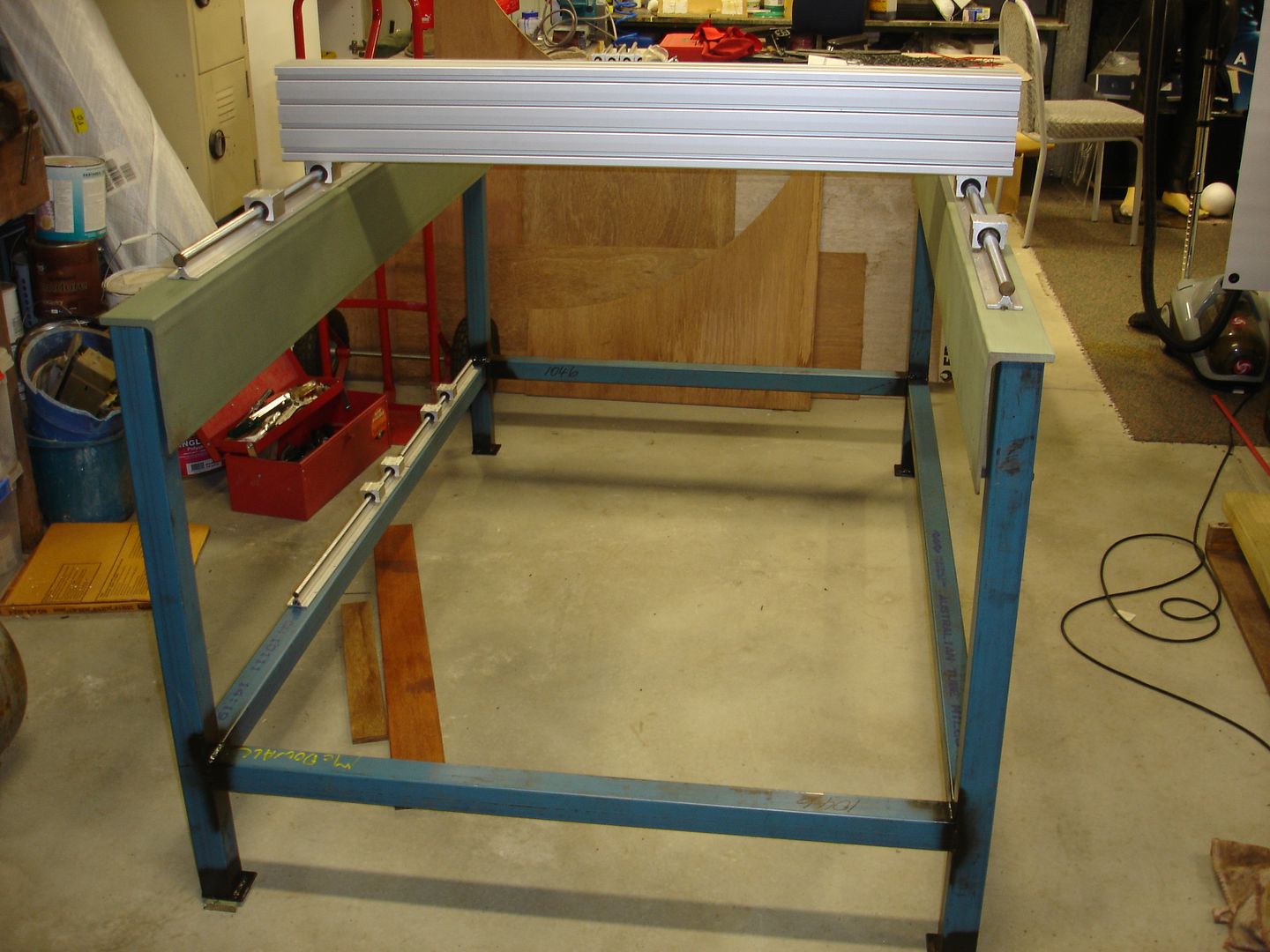
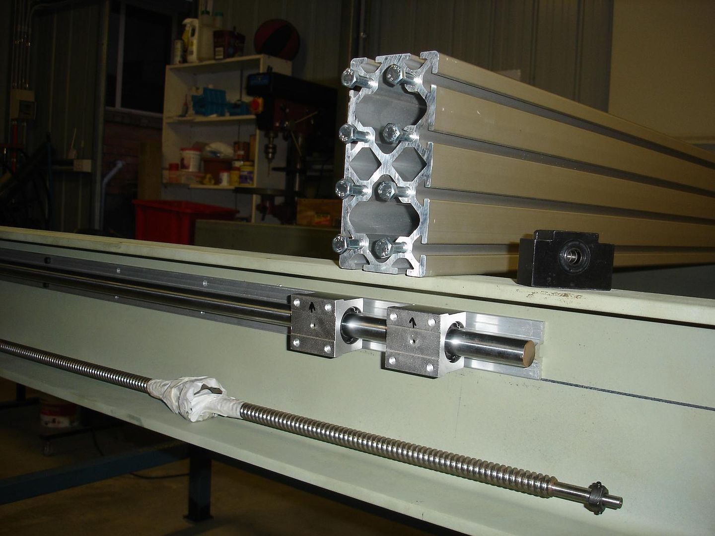
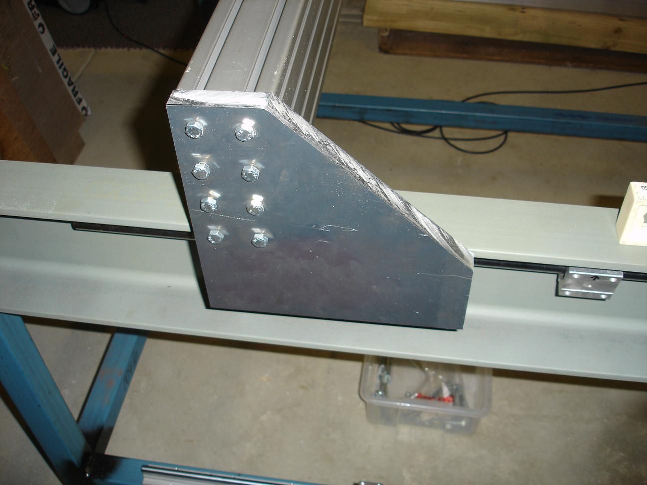
So today I tapped my first hole...lol.. then did a heap more. Rails are held in place by 6 bolts, just to make sure I lined everything up correctly. I measured it about ten times..lol.
Brad.
-
19th August 2010, 12:30 AM #75
Senior Member
- Join Date
- May 2008
- Location
- Geelong
- Posts
- 264
I was trying to think of a good way to mark the end plates of the gantry for drilling and came up with this....
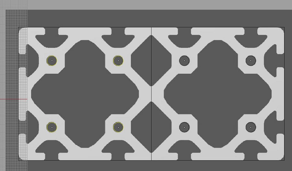
I downloaded the profile picture of the extruded aluminium for my plans. So I've used this as a template. Printed it out to scale, and just punched a hole to indicate where to drill. Seems to have worked a treat!!
Now I just need to cut the other side.
Brad.

 Reply With Quote
Similar Threads
-
Gecko G540 CNC Kits now available
By phomann in forum CNC MachinesReplies: 46Last Post: 17th January 2010, 06:25 PM -
G540 Matched Motors
By seafurymike in forum CNC MachinesReplies: 4Last Post: 25th September 2009, 02:47 PM -
Trailer - to build or not to build
By motegi in forum TRAILERS & OTHER FABRICATED STUFFReplies: 17Last Post: 6th May 2009, 03:07 PM -
Mach 3 & G540 Motor tuning
By seafurymike in forum CNC MachinesReplies: 13Last Post: 20th April 2009, 04:24 PM -
Gecko G540 - special offer
By snowyskiesau in forum CNC MachinesReplies: 13Last Post: 13th February 2009, 01:50 PM
