

 Thanks:
  Likes:
  Needs Pictures:
  Picture(s) thanks:
Results 1 to 15 of 336
Thread: G540 & CNC Build
-
4th January 2010, 04:15 PM #1
 Senior Member


- Join Date
- May 2008
- Location
- Geelong
- Posts
- 264
 G540 & CNC Build
For the past year or so I've been running a Xylotex controller and Widgetmaster and I've decided to upgrade.
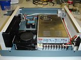
I've recently purchased the parts for a new controller, G540, 48v power, 240v fan, switch, case, relay, e-stop, etc...
Here's some pics so far.
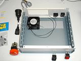
Here's my current set-up I'm about the upgrade.
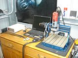
More pics to come once I start wiring.
Brad.
-
4th January 2010 04:15 PM # ADSGoogle Adsense Advertisement
- Join Date
- Always
- Location
- Advertising world
- Posts
- Many
-
4th January 2010, 07:27 PM #2
SENIOR MEMBER
- Join Date
- Dec 2005
- Location
- Brisbane
- Age
- 53
- Posts
- 293
Cool! I'll be curious to see the wiring part
 How's the laptop work with Mach3? I read on their site that they didn't recommended it at all with laptops because their power saving features screwed with the software...
-
5th January 2010, 12:41 AM #3
Senior Member
- Join Date
- May 2008
- Location
- Geelong
- Posts
- 264
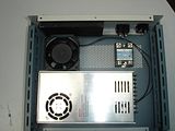
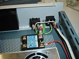
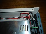
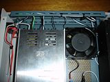
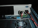
I cut the holes in the face plate tonight and started wiring. This thing is tight. I've had to solder the wires to the power switch as there just isnt enough room. But on the whole it's coming together nicely.
 The fan in the power supply blows air out and there is holes in the cover directly above. I placed the 240vac fan so it sucks air in, so there should be a good flow of air.
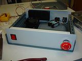
I should have it finished tomorrow night. I've no limit switch on my widgetmaster so I'll wire them in later when I start my new machine. I think I'll buy the plug for the limit switches tomorrow and cut the hole for it as I'm just now thinking this thing might not be a quick disassemble.
Brad.
www.spidey4fun.com
-
5th January 2010, 12:43 AM #4
Senior Member
- Join Date
- May 2008
- Location
- Geelong
- Posts
- 264
Hey Phil.. Yeah the lap top seems to work fine. I must have 5v output on the printer port.. but honestly I've never checked. Originally Posted by Phil Mailloux

Brad.
www.spidey4fun.com
-
5th January 2010, 12:05 PM #5
http://www.homanndesigns.com/store
- Join Date
- Dec 2008
- Location
- Melbourne
- Posts
- 269
Hi Brad,
Your stealing my idea.
I put together my prototype controller using the same enclosure. I should be stocking them when I'm back from camping.
Cheers,
Peter.
-
5th January 2010, 08:58 PM #6
Senior Member
- Join Date
- May 2008
- Location
- Geelong
- Posts
- 264
Originally Posted by phomann
Not really.. Im just making the one. You're the man to get the parts from. And Im sure if you're buying parts in bulk you'll be able to offer them cheaper then the standard price also.
-
5th January 2010, 09:10 PM #7
GOLD MEMBER
- Join Date
- May 2003
- Location
- Perth WA
- Posts
- 3,784
Hi Peter,
Not fair using a piece of ally for your second tier. I can't see where the ribbon from parallel port 1 goes from the SS. Does it run to another break out board under the ally plate?Cheers,
Rod
-
5th January 2010, 10:51 PM #8
http://www.homanndesigns.com/store
- Join Date
- Dec 2008
- Location
- Melbourne
- Posts
- 269
Hi Brad,
I know your not stealing my idea. It is an ideal enclosure for the G540 though.
Cheers,
Peter.
-
5th January 2010, 11:03 PM #9
http://www.homanndesigns.com/store
- Join Date
- Dec 2008
- Location
- Melbourne
- Posts
- 269
Originally Posted by rodm
Rod,
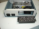
Maybe the attached photos will explain. With this setup I can chose to use the SS or the parallel port from the computer.
The SS port 1 goes out of the 2nd parallel port connector and is jumpered to the G540. By removing the DB25-DB25 jumper I can plug the Parallel port cable from the computer directly into the G540.
The 2nd port on the SS goes to the MB-02 BOB.
If there is no SS in the controller, then the 2nd DB-25 connector on the back of the enclosure goes to the MB-02 BOB.
Under the al plate is all the 240V stuff, the power supplys, relays etc. The top side is for the low voltage stuff. There is enough room for all sorts of Homann Designs boards.
Cheers,
Peter.
-
5th January 2010, 11:56 PM #10
GOLD MEMBER
- Join Date
- May 2003
- Location
- Perth WA
- Posts
- 3,784
Hi Peter,
Thanks makes sense now - nice little ribbon jumper.
I did the same sort of thing with my machine having a fall back to just parallel connection to the driver. The latest SS update has made things a lot better and I can't see myself going back to parallel port now.
I imagine it would be an advantage to you to have both inputs to test your boards and gear. I hope a ModIO finds it way in there as well. Mine is working a treat driving the console - got quite a few hours up on it now without a hitch.
Cheers,
Rod
-
6th January 2010, 02:01 AM #11
Senior Member
- Join Date
- May 2008
- Location
- Geelong
- Posts
- 264
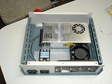
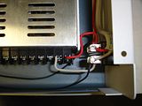
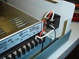
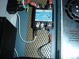
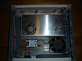
Mine's done for now... more pics. The power supply is 48vdc and my relay control voltage is 3-32vdc so I've used 2 x 2.7k resistors in parallel and a 12v Zener Diode to bring it down a little.
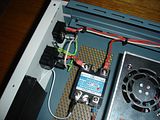
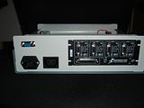
When I start the new machine that requires the limit switches I'll solder in the wires required. I do like this 240V output plugs you have on the back of yours Peter. It makes better sense to go that way then buy an adaptor plug.
I gave it a quick test run tonight and all works well. It's kind of fun pushing the spindle button and watching the mill turn off and on. I'll give it a proper run shortly.
Brad.
www.spidey4fun.com
-
6th January 2010, 10:07 AM #12
http://www.homanndesigns.com/store
- Join Date
- Dec 2008
- Location
- Melbourne
- Posts
- 269
Hi Rod, Originally Posted by rodm
The intention is to allow people with a SS and those without to use the same box design. It is just a matter of changing the configuration.
As to the ModIO, yes there is room. and loots more.
Cheers,
Peter.
-
6th January 2010, 06:10 PM #13
Senior Member
- Join Date
- May 2008
- Location
- Geelong
- Posts
- 264
There's a minor issue with the relay control. When I hit the spindle button the Kress mill powers up then very quickly turns off. If I hit the button again, the same thing happens. So I tried a 3rd time, and this time it says on. This always seems to occur shortly after start-up. If I let it run for a few moments without the spindle (output1 , pin17) switched on then try it, it seems to work. I've checked all my connections and they seem good, but there's no voltage going to the relay when this occurs, even though mack3 indicates it's on, so I can only assume the G540 isnt switching it on. Any suggestions?
-
6th January 2010, 09:22 PM #14
SENIOR MEMBER
- Join Date
- May 2005
- Location
- Cockatoo Vic
- Posts
- 996
Brad
Can you see on the diagnostics page if the output LED is coming on at those times the router is not starting?
Perhaps your resistor/zenner circuit is providing voltage or current right on the edge of turning it on or not, and under some circumstances it is not quite turning it on.
Just a guess.
Greg
-
6th January 2010, 09:51 PM #15
Senior Member
- Join Date
- May 2008
- Location
- Geelong
- Posts
- 264
The resistors and zener should be fine..
Zener Diode Voltage Regulator - Electric Circuit
This calculator allows you to work out the resistor required. I place 48V in the input voltage, 12v output and 27mA in maximum current load. Using my 24v power supply I determined the relay, without resistors or diode needed 25mA then added 2mA for the diode. This tells me I require 1333 Ohms resistance and two 2.7k resistors in parallel produce 1350 Ohms
R = (R1*R2)/(R1+R2) (2.7*2.7)/(2.7+2.7) = 1.35K
So... it should be OK.
The diagnostics page says its on.. red light is flash away, but the kress turns off in less then 1 sec. If I leave it sit for 1 minute and try again it works fine. I left it idle for 10min running and it didnt turn off again, but Im still a little nervous it might.
Perhaps the laptop parallel port out voltage at start up is an issue?
Brad.


 Reply With Quote


Similar Threads
-
Gecko G540 CNC Kits now available
By phomann in forum CNC MachinesReplies: 46Last Post: 17th January 2010, 06:25 PM -
G540 Matched Motors
By seafurymike in forum CNC MachinesReplies: 4Last Post: 25th September 2009, 02:47 PM -
Trailer - to build or not to build
By motegi in forum TRAILERS & OTHER FABRICATED STUFFReplies: 17Last Post: 6th May 2009, 03:07 PM -
Mach 3 & G540 Motor tuning
By seafurymike in forum CNC MachinesReplies: 13Last Post: 20th April 2009, 04:24 PM -
Gecko G540 - special offer
By snowyskiesau in forum CNC MachinesReplies: 13Last Post: 13th February 2009, 01:50 PM
