

 Thanks: 0
 Likes: 0
 Needs Pictures: 0
 Picture(s) thanks: 0
Results 1 to 15 of 47
-
21st December 2009, 09:28 PM #1
 http://www.homanndesigns.com/store


- Join Date
- Dec 2008
- Location
- Melbourne
- Posts
- 269
 Gecko G540 CNC Kits now available
Hi All,
I'm now putting a Kit together with the major components to put together a CNC controller based on the Gecko G540 controller.
Gecko G540 Stepper Controller Package [CC-01]
The Kit contains the following components;
- One Gecko G540 complete 4 Axis stepper system
- One 48Vdc 7.3A linear Power Supply.
- Three or Four Stepper motors
- One Mushroom Estop Switch
- One IEC Socket, fuse and switch assembly
- Two 48Vdc coil 20A contact SPST Relays
With these components you can build a controller that will run most size 23 stepper motor systems.
The G540 contains four G250 3.5A microstepping bipolar drives. The drives include anti-resonance circuitry that makes the steppers silky smooth when running.
The two relays have 48V coils so that they can by powered off the main 48Vdc supply.
I will have a wiring diagram done over the next day or two.
Cheers,
Peter.
-
21st December 2009 09:28 PM # ADSGoogle Adsense Advertisement
- Join Date
- Always
- Location
- Advertising world
- Posts
- Many
-
21st December 2009, 11:10 PM #2
Senior Member
- Join Date
- May 2008
- Location
- Geelong
- Posts
- 264
Hey Peter... Looking forward to seeing this.

Can you give any advice on the maximum length of lead between the G540 and stepper motors, and a guage of wire required?Last edited by spidey4fun; 21st December 2009 at 11:17 PM. Reason: Question asked.
-
22nd December 2009, 07:29 AM #3
http://www.homanndesigns.com/store
- Join Date
- Dec 2008
- Location
- Melbourne
- Posts
- 269
Hi,
For 3.5A Steppers, 22AWG wire is fine. As to maximum length of wire, it's a bit like "how long is a piece of string"?
How long a run are you after? 3 or 4 metres is normal from what I see.
Cheers,
Peter.
-
22nd December 2009, 09:01 AM #4
GOLD MEMBER
- Join Date
- Jul 2006
- Location
- Port Huon
- Posts
- 2,685
That's a pretty good price for all that it includes.
If I didn't already have the G540, I could see a late Christmas present coming my way...Geoff
The view from home
-
22nd December 2009, 04:53 PM #5
http://www.homanndesigns.com/store
- Join Date
- Dec 2008
- Location
- Melbourne
- Posts
- 269
I've now put up the wiring diagram. It is near the bottom of the CNC controller Package page at; Originally Posted by spidey4fun

Gecko G540 Stepper Controller Package [CC-01]
Hopefully there are'nt too many errors.
Cheers,
Peter.
-
22nd December 2009, 10:57 PM #6
Senior Member
- Join Date
- May 2008
- Location
- Geelong
- Posts
- 264
Thanks for the info Peter. I wasnt sure if the length of the lead would effect the performance. I purchase 16 metres of 22AGW wire today. 4 metre lengths.
Thanks for the wiring diagram also. Only thing I wasnt sure about was the enable switch. I notice on the Gecko website the E-stop switch is locate across these pins.
-
22nd December 2009, 11:31 PM #7
http://www.homanndesigns.com/store
- Join Date
- Dec 2008
- Location
- Melbourne
- Posts
- 269
Hi,
Pin 10 on the G540 is labelled "DISABLE Input (ESTOP)" When left open, the drive outs for the 4 drives are disabled. Additionally, Pin 15, "FAULT (Input to PC)" is made active.
If you plan to wire your ESTOP switch through the Disable input, then when you punch your EStop button, all you are doing is informing the G540 that you have a serious problem. If the problem is caused by the G540 or Mach3 malfunctioning, then you do not know if pressing the EStop will do anything at all. For all you know, your machine may continue to to run awry.
To ensure that your Estop does what it should , You need to remove power from the drives. (Also safety regulations require it). That way, if Mach3 is running awry, by removing the power, you can ensure that power is removed.
In the end, if you have a small machine, a proper EStop may not be needed. If I publish a diagram, I need to do the EStop properly.
In the diagram, the enable switch can be used to disable the drives. I find it useful to flick the switch, so I can manually adjust the axes.
If you want to wire your EStop to the disable input, then go ahead, its your call as to whether you think your system is safe.
With regard to the wire size, 22AWG wire has a resistance of 0.016Ohms/ft. For a 4 meter length that's a resistance of 0.21 Ohms.
At 3.5 Amps, The voltage drop is .73V. Not really an issue.
Cheers,
Peter.
-
22nd December 2009, 11:52 PM #8
Senior Member
- Join Date
- May 2008
- Location
- Geelong
- Posts
- 264
I'll be wiring as your diagram shows. Thanks for your assistance to date.
-
23rd December 2009, 02:56 PM #9
Senior Member
- Join Date
- May 2008
- Location
- Geelong
- Posts
- 264
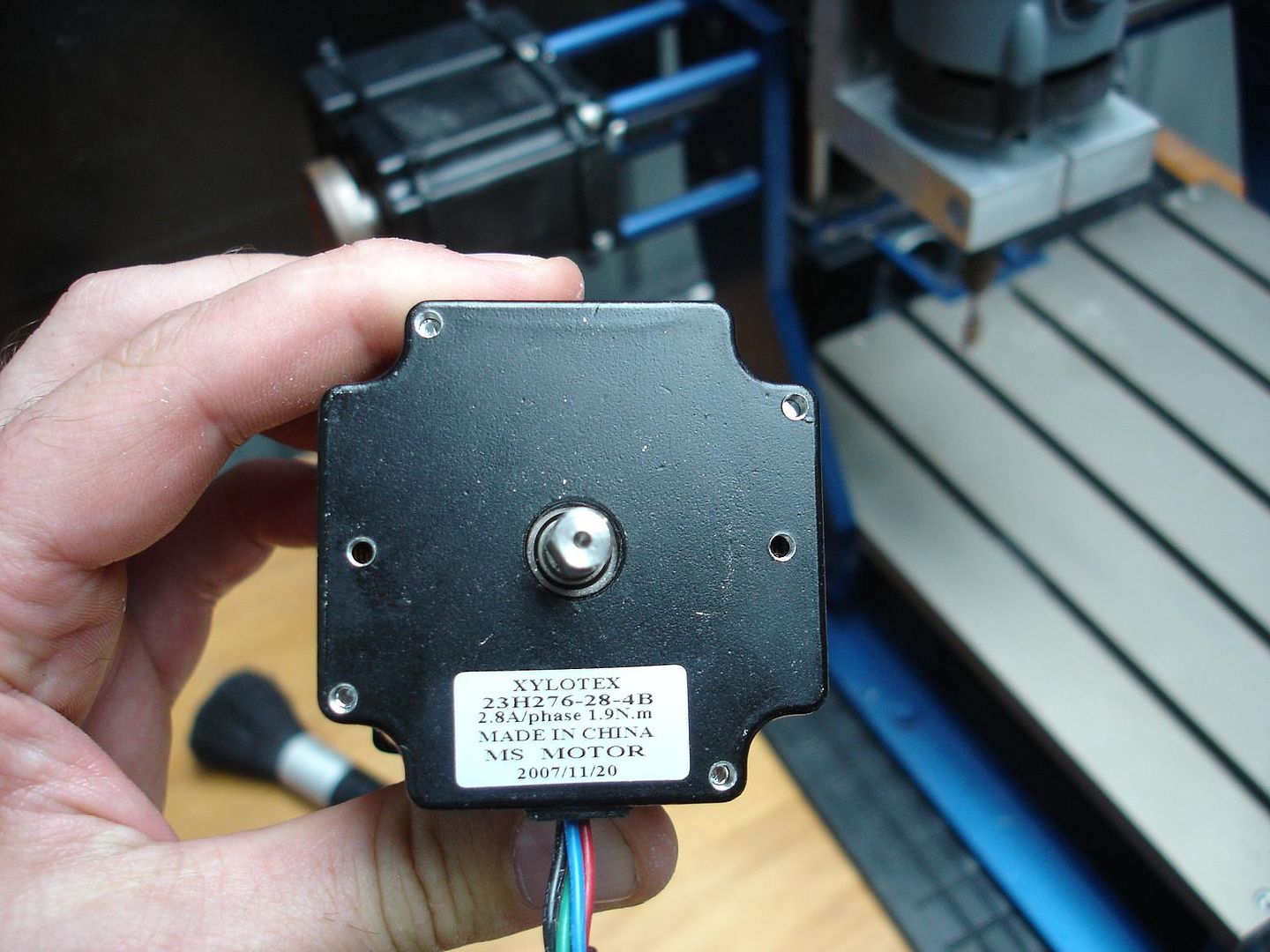
Im using 269oz 2.8A steppers so need 2.8k resistors but these seem a little hard to find.
Can I find a RES 0.5W MTL 2K7 1% but the tolerance is only +- 27ohm or I can get two 5.6k 1/2watt and put them in parallel to get 2.8k but I'll have 1watt. Would this be an issue?
What do you suggest?
-
23rd December 2009, 03:25 PM #10
Senior Member
- Join Date
- Dec 2007
- Location
- Melbourne
- Posts
- 105
In the Gecko 540 datasheet it states that the current set resistor is 1k per Amp of motor current so a 2k8 will result in 2.8A per motor phase. A 2k7 resistor will result in 2.7A per motor phase which will be OK. Two 5k6 in parallel would be OK as well but just a lot more trouble to go to. The 1W refers to the maximum power dissapation the parallel combination can handle so this is OK as well.
-
23rd December 2009, 03:36 PM #11
GOLD MEMBER
- Join Date
- Jul 2006
- Location
- Port Huon
- Posts
- 2,685
You can get 2.8k 1% resistors locally from RS-Components or from Futurlec. Originally Posted by spidey4fun
The Gecko spec says that the resistor can be from 1/10 to 1/2 watt. Anything larger that 1/2 watt may be a bit big to fit into the DB-9 shell.Geoff
The view from home
-
23rd December 2009, 03:40 PM #12
Senior Member
- Join Date
- Dec 2007
- Location
- Melbourne
- Posts
- 105
spidey4fun,
I have just taken a look at Peter Homann's wiring diagram (probably should have done that before I posted my previous reply) and it says that for the 269 oz-in steppers the current sense resistor should be 2k - i.e 2A per motor phase. The 387 oz-in steppers have a current sense resistor of 2k8 (i.e. 2.8A per motor phase). The current rating may depend on the actual stepper motors used but it may be worth checking that your 269 oz-in steppers are indeed 2.8A and not 2.0 A.
-
23rd December 2009, 05:07 PM #13
http://www.homanndesigns.com/store
- Join Date
- Dec 2008
- Location
- Melbourne
- Posts
- 269
Originally Posted by grunto
Hi,
I've made a mistake in my diagram. The 269 oz-in are 2.8A per ph and the 387 oz-in are 3.5A per phase. - Sorry. I'll fix the diagram.
As to getting 2.8K resistors, you can get 1% ones for RS Components. If it was me, I'd just use 2.7K ones and loose the 100mA
Cheers,
Peter.
-
23rd December 2009, 05:41 PM #14
http://www.homanndesigns.com/store
- Join Date
- Dec 2008
- Location
- Melbourne
- Posts
- 269
Hi,
I've now updated the wiring diagram, and also added an IEC output plug for one of the relays for switching a spindle motor etc. The other relays contact are now bought out to an axillary connector.
Cheers,
Peter.
-
23rd December 2009, 05:53 PM #15
Senior Member
- Join Date
- May 2008
- Location
- Geelong
- Posts
- 264
No need to reply as Peter already did... but seeings as I took this nice picture.
Nice update on the wiring diagram. I'll be using the relay to switch off the Kriss Mill so this is perfect.
Brad.


 Reply With Quote
Similar Threads
-
G540 Matched Motors
By seafurymike in forum CNC MachinesReplies: 4Last Post: 25th September 2009, 02:47 PM -
Gecko sale time again
By Greolt in forum CNC MachinesReplies: 33Last Post: 29th August 2009, 07:23 PM -
Mach 3 & G540 Motor tuning
By seafurymike in forum CNC MachinesReplies: 13Last Post: 20th April 2009, 04:24 PM -
Gecko G540 - special offer
By snowyskiesau in forum CNC MachinesReplies: 13Last Post: 13th February 2009, 01:50 PM -
Cheap gecko drives
By snowyskiesau in forum CNC MachinesReplies: 28Last Post: 19th September 2008, 08:28 AM
