

 Thanks:
  Likes:
  Needs Pictures: 0
 Picture(s) thanks:
Results 46 to 60 of 88
Thread: Entry hall table for a niece
-
3rd February 2020, 04:55 PM #46
 GOLD MEMBER


- Join Date
- May 2007
- Location
- Sth Gippsland Vic
- Posts
- 4,389
 Perth to Sydney . If it did go bang its a long trip back to fix it . I'm flipping a bit on this . You better seal it well on the inside .
 Originally Posted by derekcohen

Think Id get out the iron though . While its there in front of you .
We had a sofa table come in once . Same sort of thing as this .
Google Image Result for https://i.pinimg.com/originals/b2/37/b4/b237b48c967d8c2e7cf9bc312f8b03d7.jpg
Someone had glued wood going the opposite way across the grain on the under side . It sent the top into a fit . Big ups and downs and cracks as well . The big move from the UK to AU could have been the reason it moved so bad. No idea where the repair was done though just assumed that much movement was because of that. A shipping container full of wood in the sun at the equator sitting on a ship would get the same treatment as if it was in an oven .
Everytime I have seen it done the end result isn't to good . Its just a matter of time . My end comment in last post at the end wasn't written to well . It is very strong , but , I meant at some time it will go . If the build up is great enough .
Rob
-
3rd February 2020 04:55 PM # ADSGoogle Adsense Advertisement
- Join Date
- Always
- Location
- Advertising world
- Posts
- Many
-
4th February 2020, 02:47 AM #47
Be inspired. Be creative. Be bold.
- Join Date
- Apr 2001
- Location
- Perth
- Posts
- 10,821
The case was glued up yesterday, with everything tight and square as one could wish, but I did not sleep well. I was haunted by the thought that there was a problem that would come to a head some time in the future.
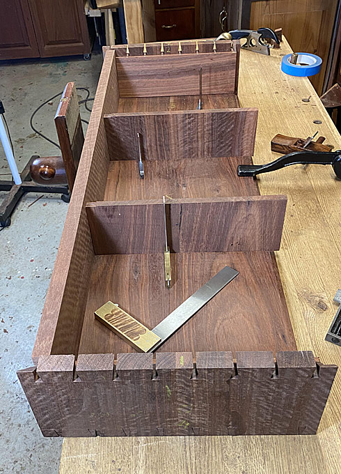
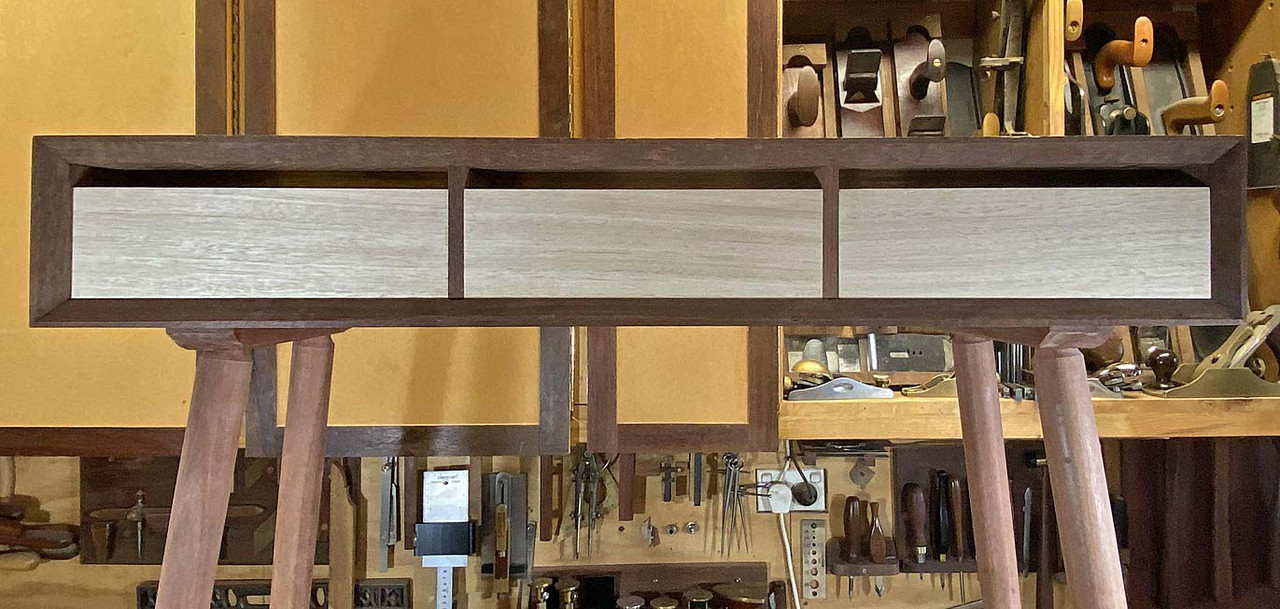
If you look at the grain direction of the two centre drawer dividers, you notice that the grain is vertical. That is the way it should be. Wood moves, expands and contracts. It does this in reaction to moisture in the air. When it moves, it does so across the grain. That is why solid wood drawer bottoms have grain across the width - allowing the drawer bottom to move towards the back of the drawer, rather than towards the sides (where it will be blocked and then buckle).
These drawer dividers will be butted up against the rear of the drawer lips and act as drawer stops. The front third of the divider will be glued in the dado, forcing any expansion towards the rear of the case. All good.
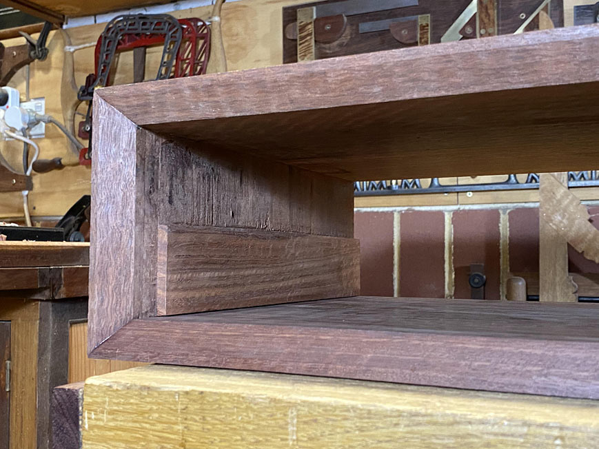
The two spacers at the inside ends of the case have the grain running horizontally. I glued this in before I realised that I had cut them this way. I had done the same with the internal dividers, but re-cut them, as shown in the previous article. The end spacers will expand vertically, and to allow for this, I provided a 2mm gap below and above the panels. That is what kept me awake.
The end spacers are 6mm thick. The case, to which they are glued, is 20mm thick and about 40mm wider. Initially I was concerned that the spacer would be overwhelmed by the case moving, and buckle. Having thought some more about this, I am no longer concerned that this will occur. Why? Because movement in the case would instead "stretch" the spacer length-wise. I started to breath again.
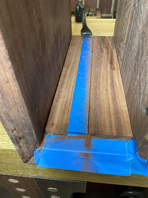
In the end, I decided to reduce the height of the spacers by half. This would allow them plenty of space to expand, when necessary, as well as reducing their impact inside the case.
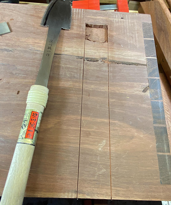
Here is one side ...
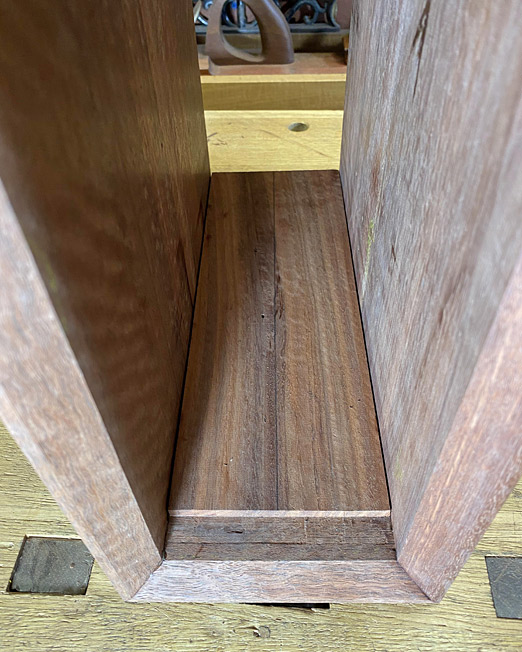
Taped for visibility and protection ...
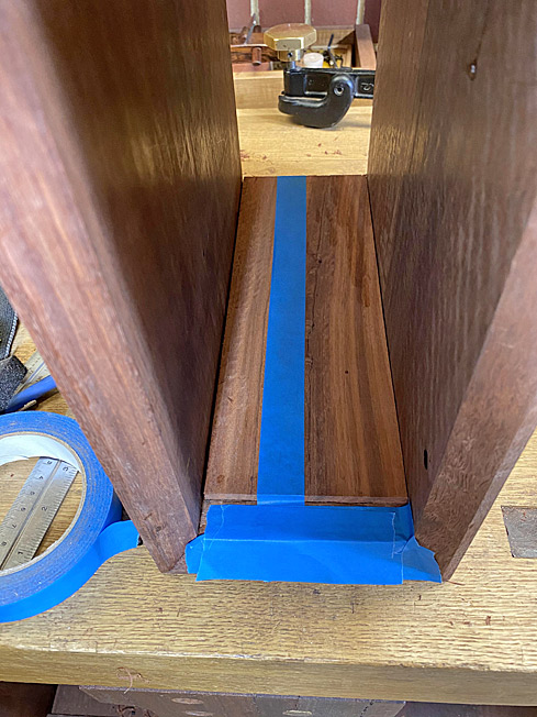
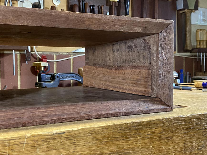
The saw is a 16" Wenzloff & Sons tenon saw (10 tpi) ...
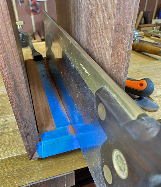
Three kerfs ...
Deepened with a Japanese Azebiki ...
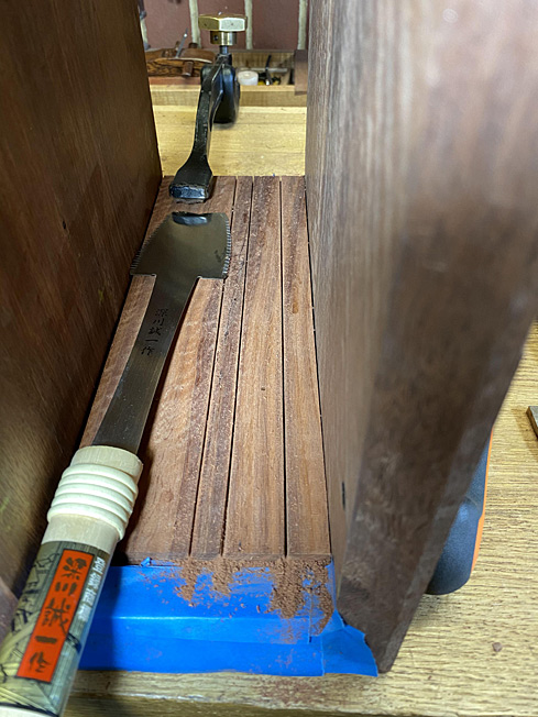
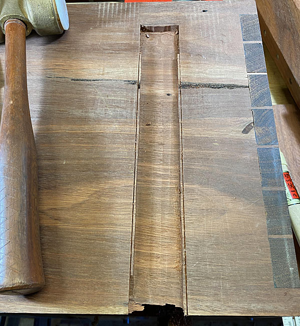
... and split out with a firmer chisel ...
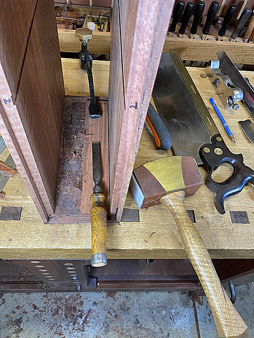
A Bahco carbide scraper cleans up ...
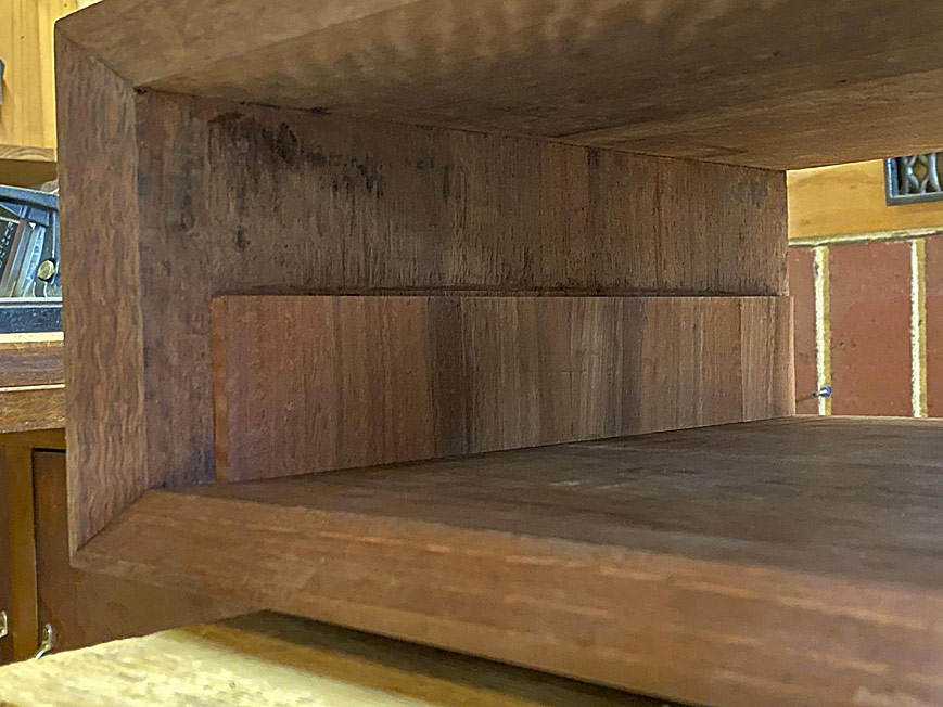
The result ...
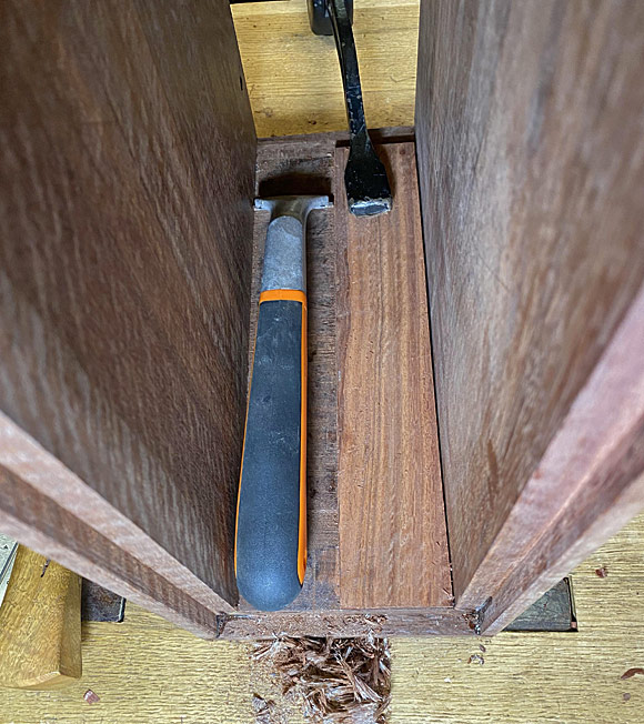
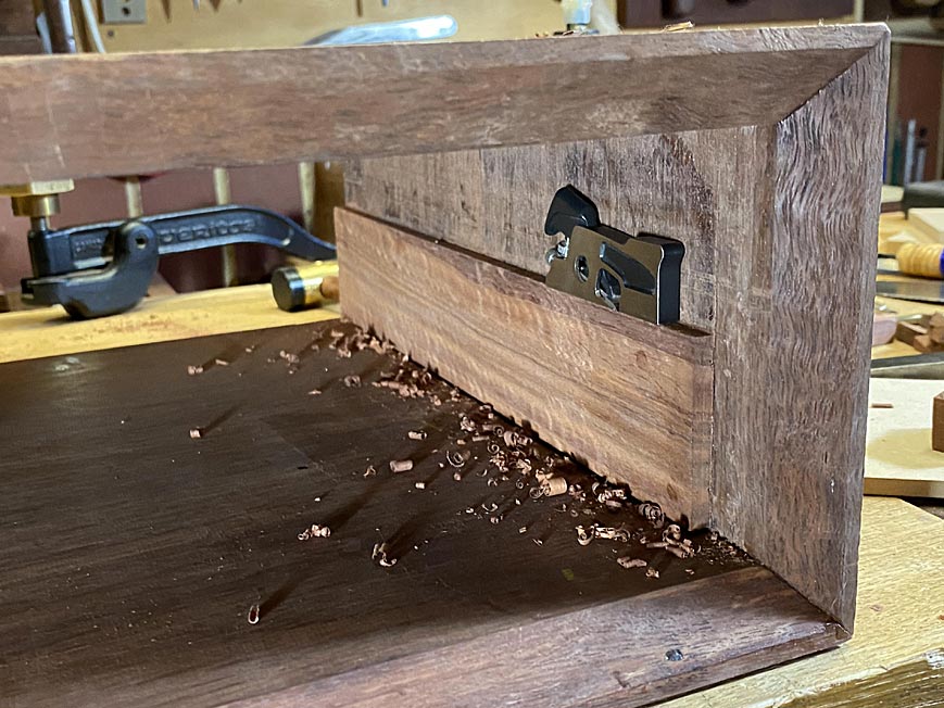
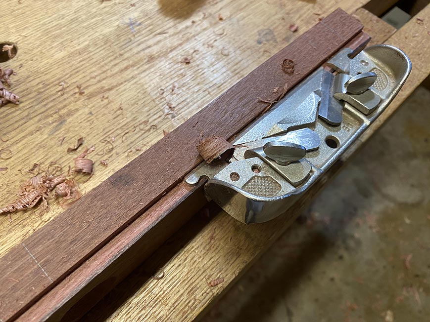
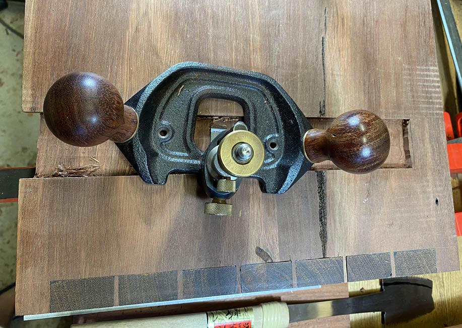
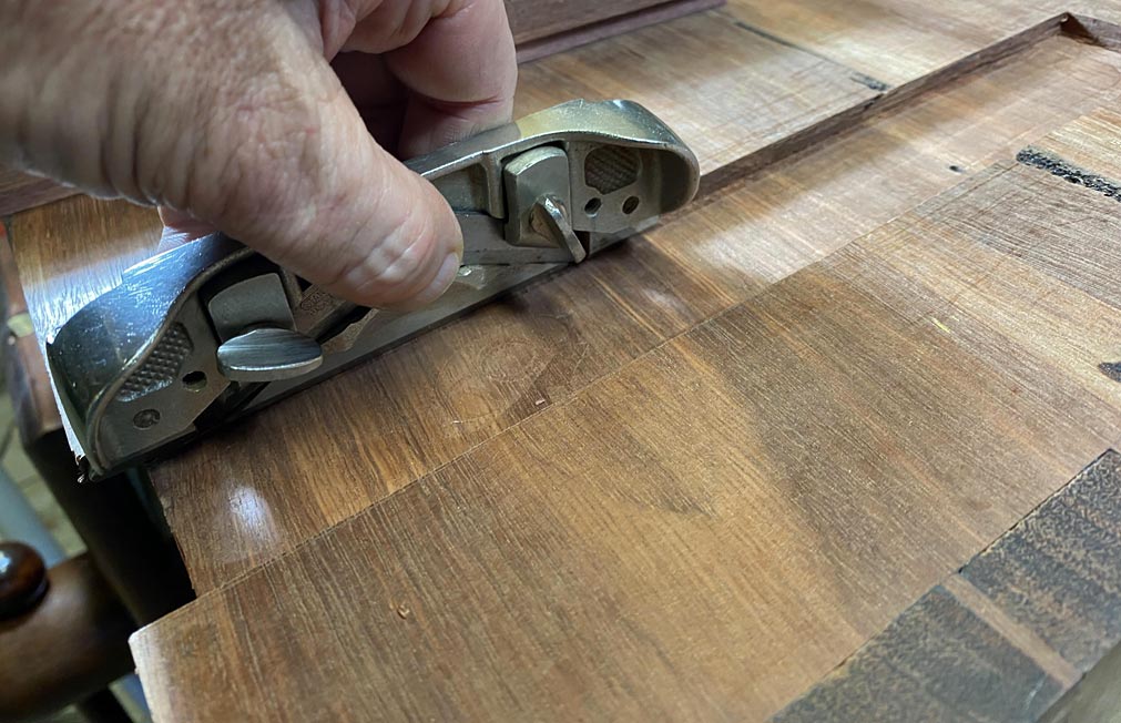
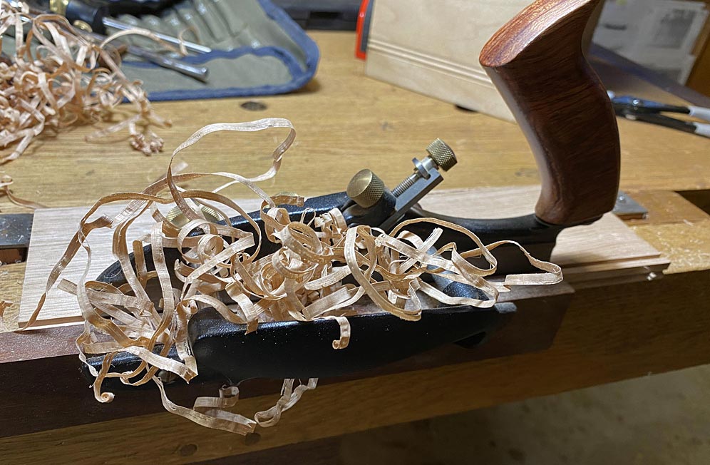
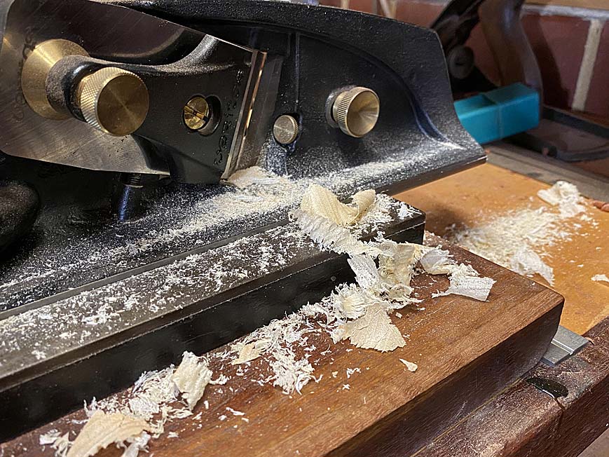
Final cleanup was aided by the only shoulder plane that fitted inside the space ...
...
Regards from Perth
DerekVisit www.inthewoodshop.com for tutorials on constructing handtools, handtool reviews, and my trials and tribulations with furniture builds.
-
6th February 2020, 09:46 AM #48
Senior Member
- Join Date
- Sep 2018
- Location
- Tasmania
- Age
- 53
- Posts
- 186
Bet you're glad you've done it now. Great result, Derek.
Regards Adam
-
17th February 2020, 02:56 AM #49
Be inspired. Be creative. Be bold.
- Join Date
- Apr 2001
- Location
- Perth
- Posts
- 10,821
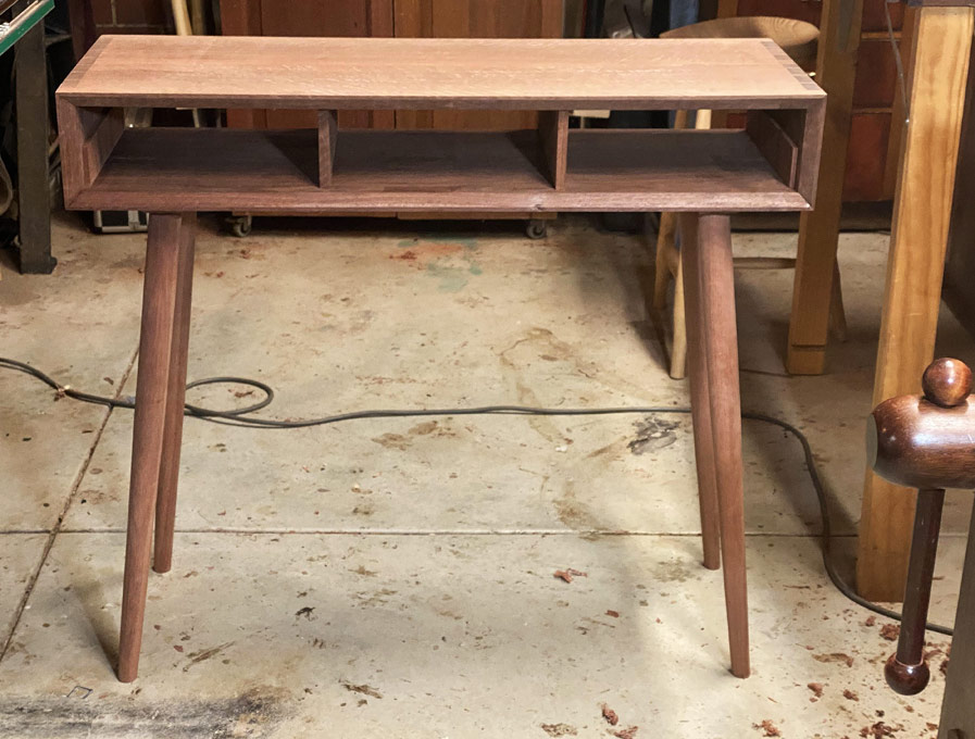
As a reminder, we are building a version of this table ...

The plan is to attach the legs, which were made near the start of this project.

The attachment method is by inserting the legs into compound angle mortices in a base, which will be fixed to the carcase with a tapered sliding and stopped dovetail. We don't mess about here!
It will be necessary to do this over two articles, the first being the base for the legs, which will be dovetailed (tails). The second will be the socket (pins) for the base.
Before we begin, I want to mention what I did at the end of the last session. I had replaced the central drawer dividers as the grain ran in the wrong direction. The spacers at the ends also did so, and my response was to cut out half the spacer ...
Well, I fretted over the end spacers, and just could not leave them this way. Encouraged by the way the halves had come out cleanly, I removed the remainder and replaced the spacers with correctly grained versions ...
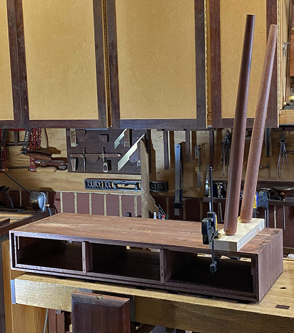
OK, onto the leg base ...
I spent a while playing with angles for the legs, and finally accepted this (mocked up base) ...
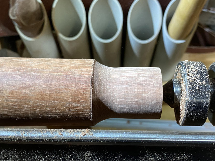
I have drilled angled mortices with a brace on a number of occasions. This time I decided to used a drill press and some Japanese Star-M augers, which are specially designed for this type of work (no lead screws). I built a 10 degree ramp for the resultant angle. The auger is 30mm ...
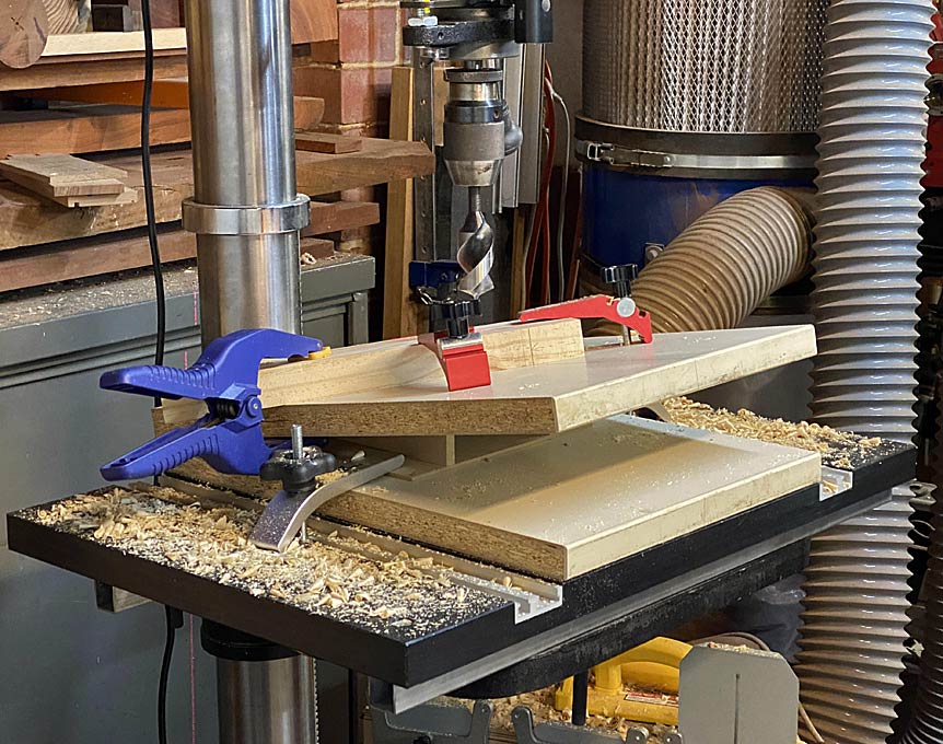
[
The tenon is straight, but the mortice will receive a slight reaming, and the tenon will be glued and wedged. This is probably overkill since the weight of the case rests on the legs.
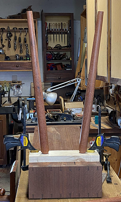
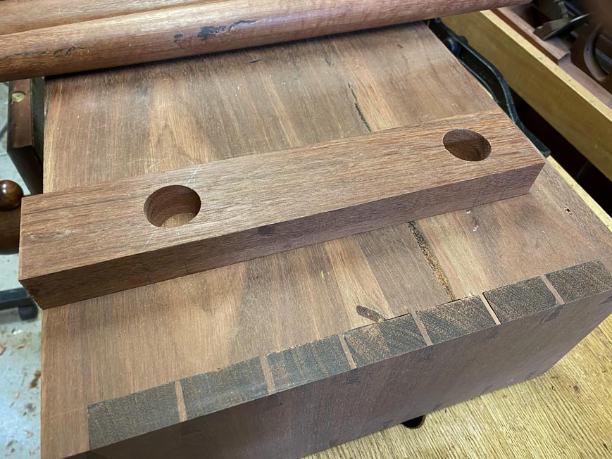
These are the bases for the legs. The final prototype is at the rear ...
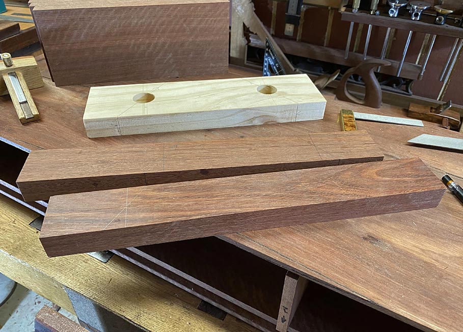
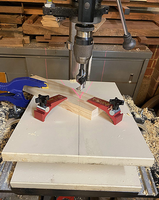
Drilling the bases ...

The design requires that the legs do not go over the boundary of the case (to avoid tripping over them) ...


This is how they should be ...
There was a small dilemma: The base at one side measures 3" from the end ...
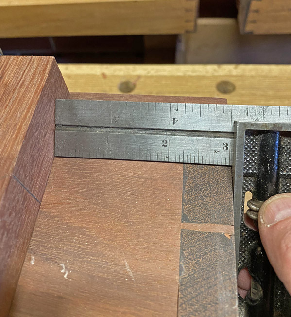
... and the other side measures 1/4" further ...
I could not work out how this occurred. The angles are the same. In fact, I made another set of bases, and the same error showed up again - exactly the same!
So what to do? Actually, the decision was obvious after a little think - make the bases the same. What is more likely to be noticed is if the bases are different distances from the sides. No one will notice a 1/4" difference where the legs hit the ground. So be it.
This is one of the bases for dovetailing ...
First step is to remove a 2mm taper from one side. The taper will be on the inside of the base, with the outside parallel to the side of the case.
Taper line drawn ...

Easiest way to do this is with a #604 smoother ..
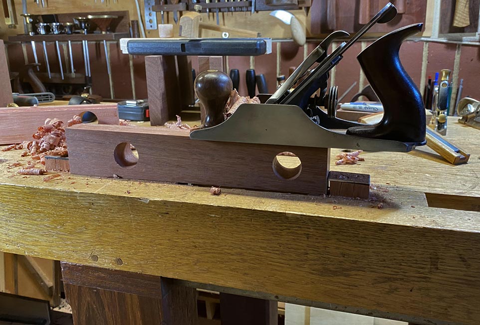
This is the one end of the base ...
.. and this is the other end ...
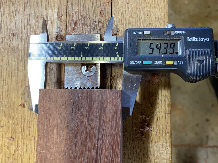
mmmm .... 0.39 mm oversize. What to do ...? I'm kidding
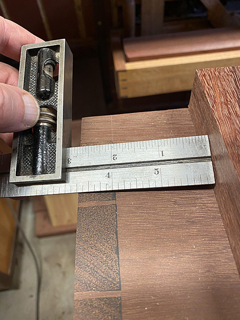
The dovetails will be 7mm deep. A shoulder was planed with a rebate plane ...
The squareness of this rebate is important, so check ...
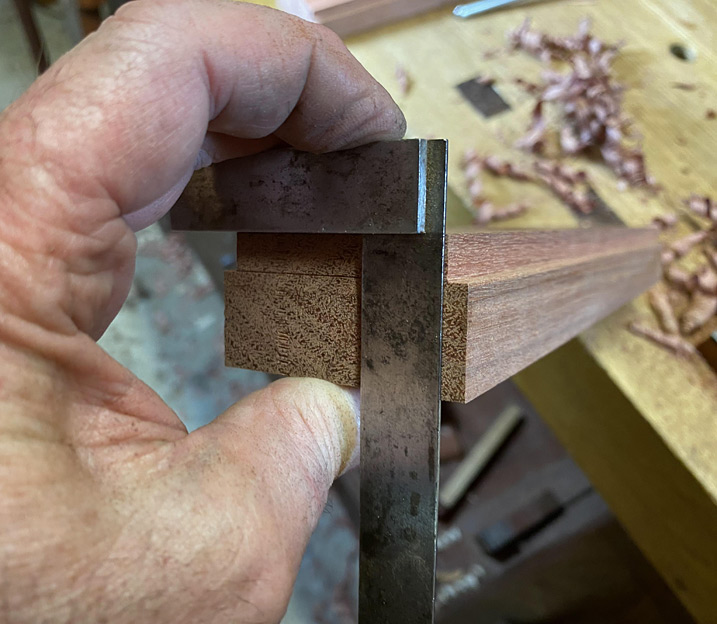
The dovetail is now to be created, and the preparatory step is to colour the outer edge of the rebate with a sharpie. This will warn that the planing does not lower the external edge of the rebate.
The dovetail is created with a modified Stanley #79 edge plane ...
The fence has a 1:6 ratio wedge ...

Details of this dovetail plane here: http://www.inthewoodshop.com/ShopMad...Stanley79.html
The result of planing. That is a 1:6 dovetail marker ...
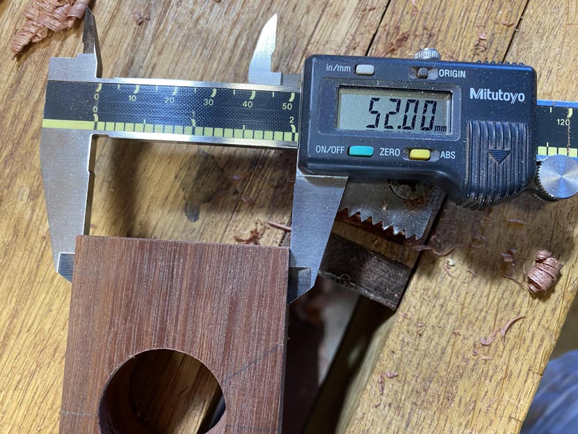
So what are the numbers for the taper? This will give an indication of the accuracy of the joint.
One end is 44.12mm ...

... and the other is 46.46mm, which is a difference of 2.34mm.

This will work - the pin socket is measured from this (in the same way as dovetails for a drawer.
The reason for the 7mm depth? The case is 20mm thick. the dovetail should be about 1/3 of this thickness. I decided to take it to the depth of the rebate for the rear panel ...
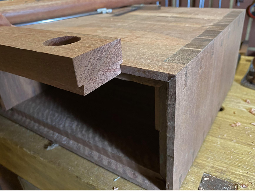
So, here is one of the completed bases ...
And this is where it will be fitted ...
Regards from Perth
DerekVisit www.inthewoodshop.com for tutorials on constructing handtools, handtool reviews, and my trials and tribulations with furniture builds.
-
17th February 2020, 11:12 AM #50
Dances with splinters
- Join Date
- Jul 2005
- Location
- Oberon, NSW
- Age
- 63
- Posts
- 13,360
Given the replicability of that 1/4" error I'm wondering as to how you dressed the bases... did you dress a long piece then dock suitable lengths or did you do each base individually?
If the former, it could easily be a minor deviation from square. Given the lengths of the legs, it would only take a poofteenth of a degree out of true to move each pair 1/8" out of alignment, totalling the 1/4" when fitted.
Of course, it could also be the cabinet itself has racked slightly... if the legs are 3x the height of the sides, it'd only need to be 1/32" out of true for the same result. But somehow, given your eye for detail, I doubt this is the case.
If, on t'other hand, you dressed each base separately, well... "How curious!"
(No critique intended; I've been sitting on my log watching this WIP in fascination. So when oddities like this pop up, I can't help but wonder 'why is it so?' )
)
- Andy Mc
-
17th February 2020, 04:35 PM #51
Be inspired. Be creative. Be bold.
- Join Date
- Apr 2001
- Location
- Perth
- Posts
- 10,821
The legs are identical in length and the tenons are exact as they are turned on the same centre.
The two issues that may have occurred are: even though one imagines drilling using a jig is perfectly accurate, likely something moves (the bit is taken with the grain). Still, I drilled the bases a few times and got the same results. The second possibility is that the side of the case is not perfectly square. Everything was square - very square - at glue up, but I used a ROS to flush the dovetails, and this may have rounded the side slightly.
I am not concerned. It will not be evident at the end.
Regards from Perth
DerekVisit www.inthewoodshop.com for tutorials on constructing handtools, handtool reviews, and my trials and tribulations with furniture builds.
-
18th February 2020, 03:43 AM #52
Be inspired. Be creative. Be bold.
- Join Date
- Apr 2001
- Location
- Perth
- Posts
- 10,821
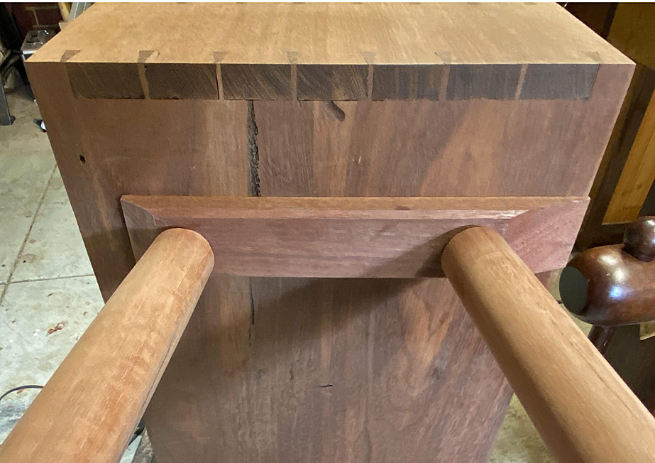
Following hot on the heels of the last post, where we created the male or tail section of the tapered sliding dovetail, now comes the female or pin socket to house the base for the legs.
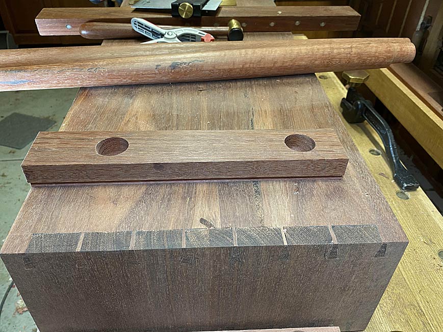
These are the bases. This post will focus on the socket for the one closest the camera.
The base is positioned exactly 3 1/4" from the side. The tapered side is on the inside, with the outside face square to the front and rear of the case ...
This process is essentially the same as transferring marks from the tail- to the pin board with drawers.
The base tapers towards the toe, that is, the sliding dovetail will tighten up as the base is pushed into the socket.
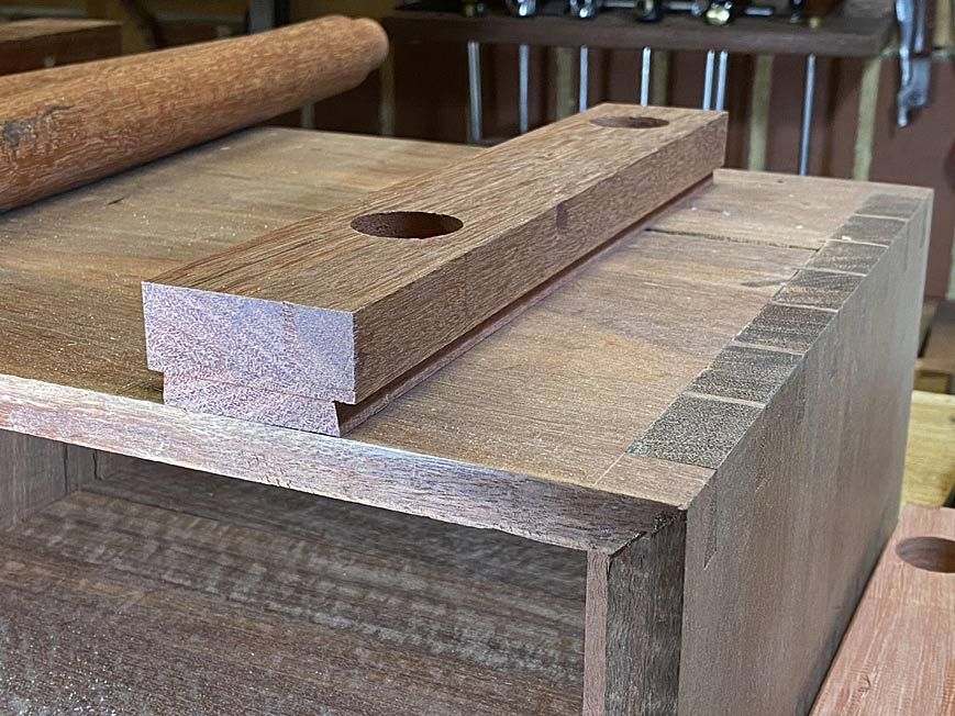
The first step is to register the far end of the base in such a way that the position is repeatable. This is done by placing a long board along the "square" side. The position for the end of the board is marked ...
Now the base can be stood up to mark inside the tail with a scratch awl. You can make out the mark aligning the baseline of the tail ...
Look carefully for the dots.
This is repeated at the other end.
The dots are now joined up ...

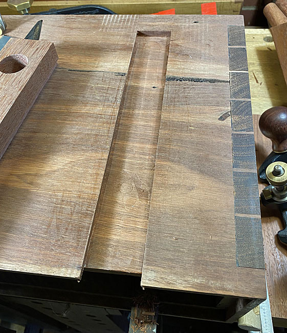
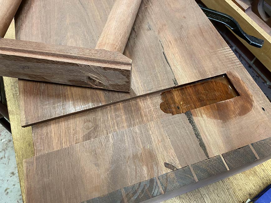
The plan is to saw the socket sides, as if sawing dovetails in a drawer. The angle ratio is 1:6, as it was with the base. Since the socket is blind or stopped, the saw needs to have space in which to begin the cut. An area at the toe is excavated with a router.
The depth of the cut is set using a 7.0mm drill bit. I am aware that the actual depth is 7.5mm, but this will be a second pass. I intend to clear the waste with the router - this Jarrah is bloody hard, and I am not a masochist!

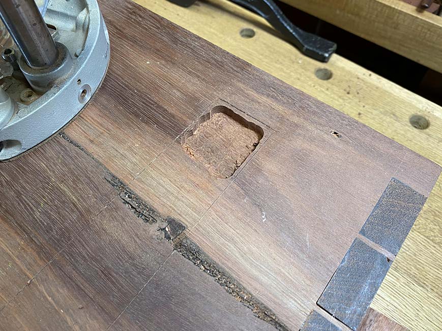
Using an angled saw guide, the end is chopped to the line ..
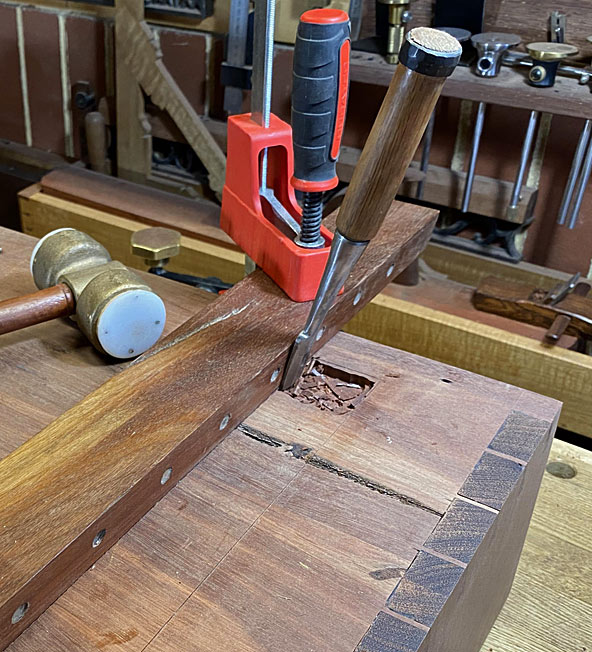
Now this is space to register the azebiki saw ...
I have roughly marked a depth to aim for ...
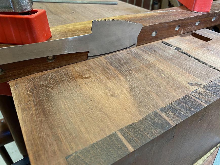
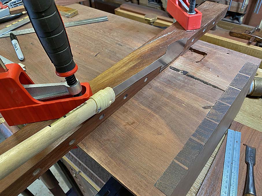
Both sides have been sawn ...
The waste is removed with the router, leaving a few mm close to the sides ...
This is chopped away with a chisel in two passes, and then cleaned up with a hand router ...
The side rebate #79/dovetail plane is used to clean any rough sections ..
The power router drops a 0.5mm to 7.5mm and this is cleaned up ...
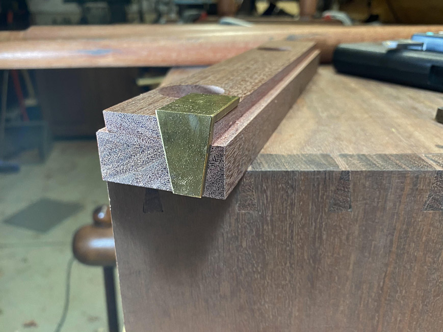
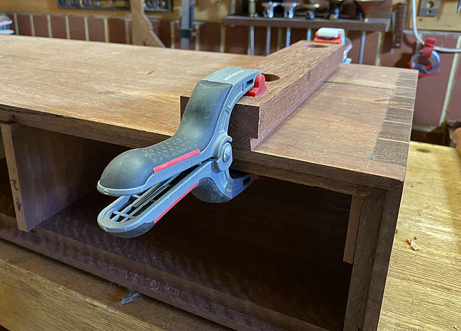
Amazingly, the base slides in and tightens up about 1/4" from the end. It will need a tap to be fully secure.
That's it for now.
Regards from Perth
DerekVisit www.inthewoodshop.com for tutorials on constructing handtools, handtool reviews, and my trials and tribulations with furniture builds.
-
23rd February 2020, 04:59 AM #53
Be inspired. Be creative. Be bold.
- Join Date
- Apr 2001
- Location
- Perth
- Posts
- 10,821
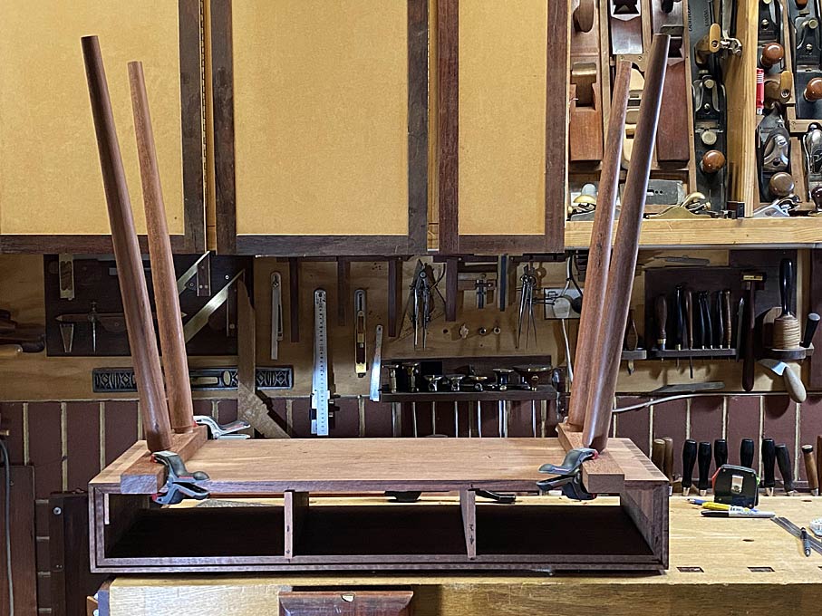
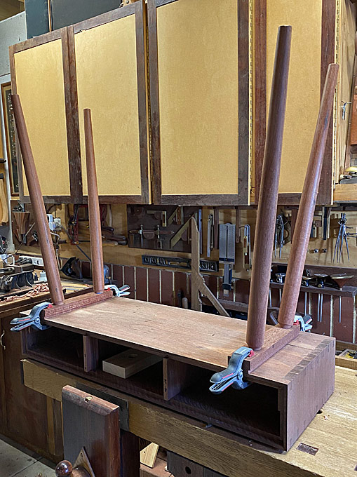
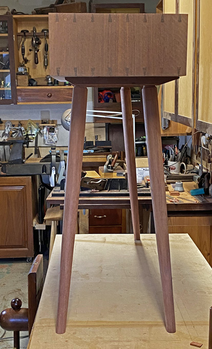
The legs are on. I must admit to mixed feelings at this stage. This is not my style of leg, but it is what my niece wants. Perhaps I will feel differently with a finish on the wood.
The tenons were kerfed for a wedge ...
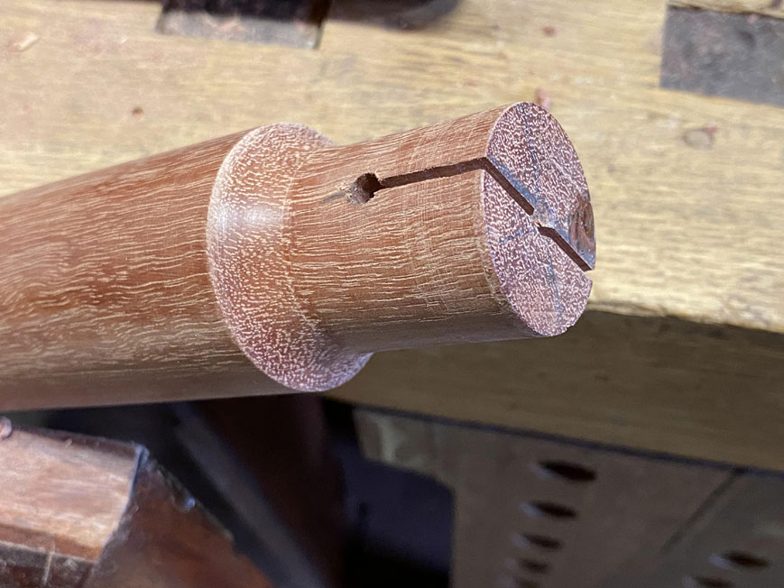
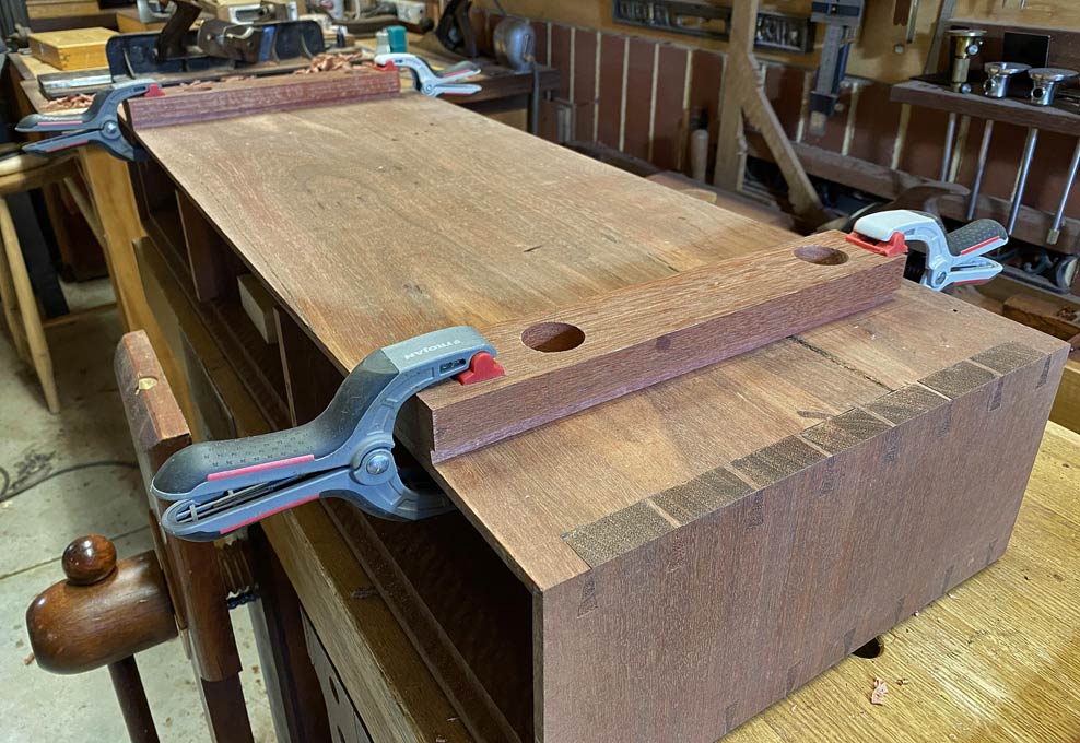
Installed in the bases ...
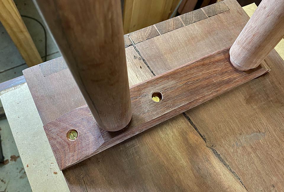
And glued into the socket. Note that only the first third is glued. The rear is free to move ...
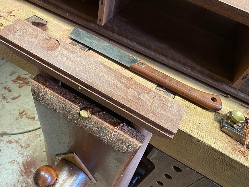
The bases have been shaped to reduce their impact ...
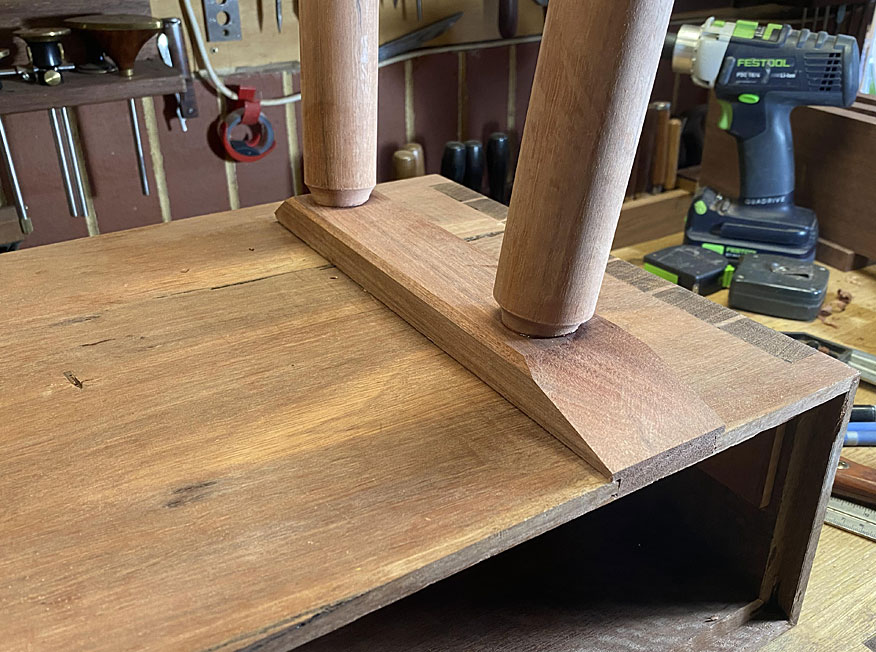
The legs were evened up ..
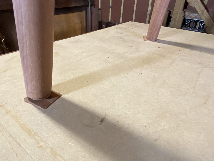
Side view from underneath (one does not see the base otherwise) ...
Regards from Perth
DerekVisit www.inthewoodshop.com for tutorials on constructing handtools, handtool reviews, and my trials and tribulations with furniture builds.
-
23rd February 2020, 12:38 PM #54
 GOLD MEMBER
- Join Date
- Apr 2006
- Location
- Hobart
- Posts
- 5,124
But that is the important bit, Uncle Derek. Perhaps you can take solace from Michelangelo's experiences in painting the ceiling of the Sistine Chapel; he wrote quite extensively, complaining constantly about three factors: Originally Posted by derekcohen
- It took him four years on high scaffolding working overhead, and he quickly developed a persistently sore neck and back,
- he was constantly spattered with paint - "worse than pigeons", and
- (Even worse), Pope Sixtus IV continuously offered advice on how to paint the ceiling. "I think we could have another cherub over here, Michelangelo, and perhaps Heaven could be a little bluer, and, oh, I see you have painted Adam in my likeness; how appropriate!.......
Graeme
-
24th February 2020, 03:26 AM #55
Be inspired. Be creative. Be bold.
- Join Date
- Apr 2001
- Location
- Perth
- Posts
- 10,821
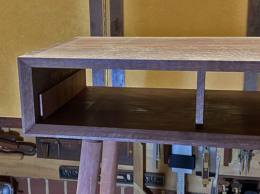
It's time for the drawers. Once again there is a challenge. The design calls for drawer fronts that stretch across the front without being broken by drawer dividers. In other words, "lipped drawers".
There are two ways to do this. The easy way is to used "planted fronts", that is, attached fronts to the front of a box ...
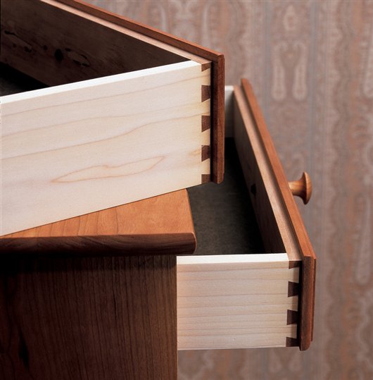
The hard way is to make the drawer front a single piece. This requires rebating the drawer front and forming a half blind dovetail in the side of the rebate. Courtesy of Christian Becksvoort ...
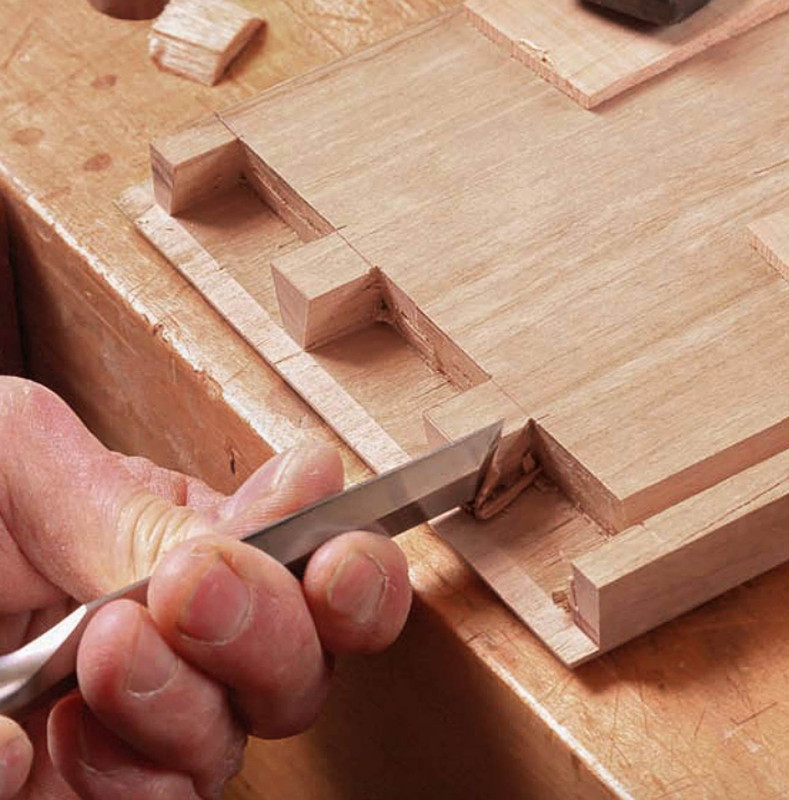
I've chosen the high road (sigh).
Today I spent my time preparing for three drawers. Why three and not two, as in the original design? Simply because I can build them narrower, and this will make them less likely to rack. They'll end up somewhere around 280mm wide and 290mm deep. I anticipated that 375mm wide and 290mm deep would be a disaster waiting to happen. The only way drawers that dimension could work is on runners, which I do not do.
The wood for the drawer front is more Fiddleback Jarrah (by request), while the remainder of the drawer is quarter sawn Tasmanian Oak (which is actually a Eucalyptus, and is quite unstable unless quarter sawn. I keep a stock for drawers). It is a lot like US White Oak in appearance and hardness.
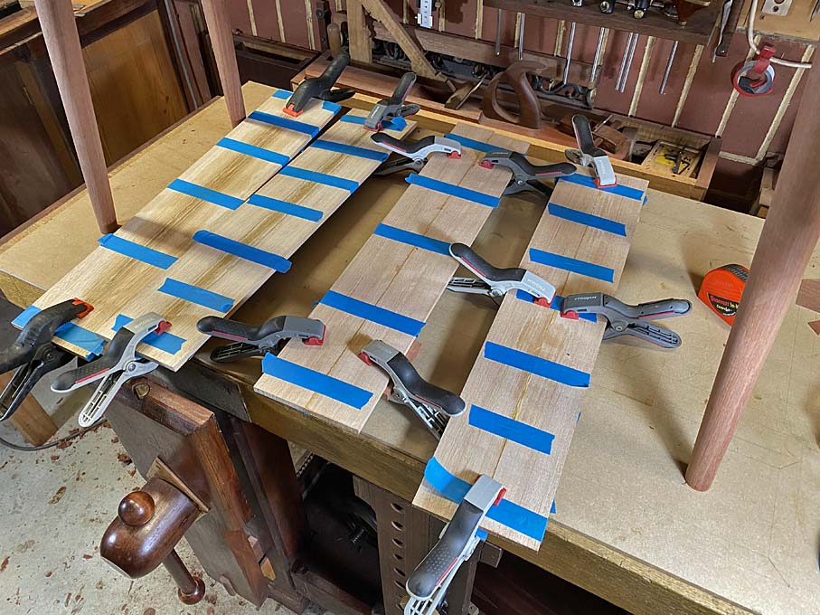
I have a bunch of narrower boards, which I re-sawed to make 7mm thick drawer sides, and glued together two to get the height needed ...
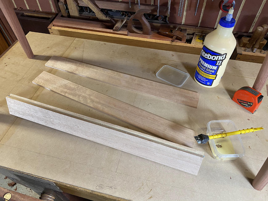
No clamps, just blue painter's tape, which is stretched across. It pulls the edges together.
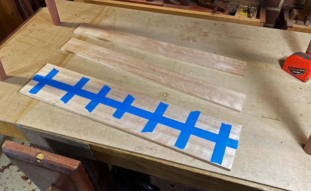
This is enough for 4 drawer sides (one spare) ...
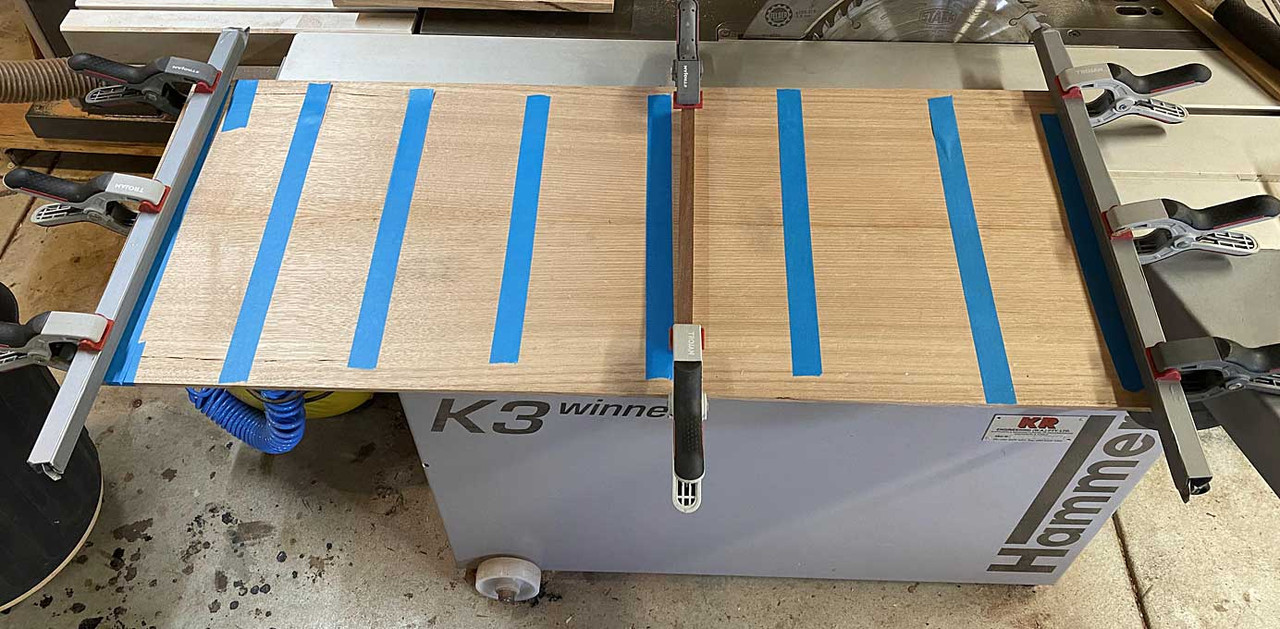
The drawer bottoms will be 1/4" (6.35mm) thick ..... I cannot go metric here as my plough blade is imperial .... this is re-sawn from a wide board, which saves some effort as only two boards are needed for the bottoms (the grain runs across the drawer) ...

Same trick with the blue tape, and cauls are also added to keep it flat. This will be sawn up at the time it is needed, and the panel will remain in the cauls until thn.
The narrow drawer sides necessitate using drawer slips, which is a strip added to the sides with a groove for the drawer bottom. This also adds extra width as a runner.
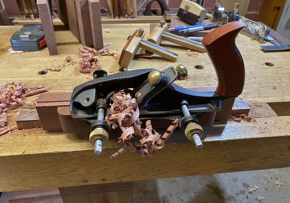
The slips are made with a plough plane. In this case, I used both a Veritas Small Plow (to plough the groove) and the Veritas Combination Plow (to plough a bead - the bead lies at the join of the slip and drawer bottom). Setting up both save time switching set ups back and forth, and once begun, making these slips was a quick process ...
First plough the bead ...

A tip on how to avoid over-planing the bead. This comes from David Charlesworth. Scribble pencil along the top of the bead, and when it is gone, the bead is complete ...
Now flip the board around to plane the groove ...
The first line is where the groove begins, which is 3mm below the bead. There will follow a 1/4" groove, and there will be 4mm below this to support the groove/drawer bottom. This makes the slip a smidgeon over 12mm high. It is 10mm deep, which allows for a 5mm deep groove.
As mentioned, once set up, no further marking is necessary. Just plane ...
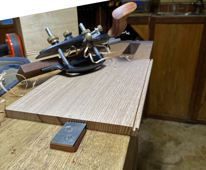
... and then rip off the slip on the table saw.
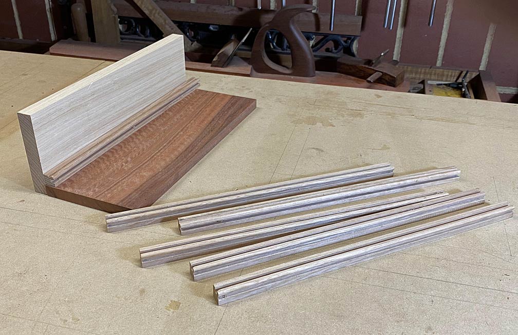
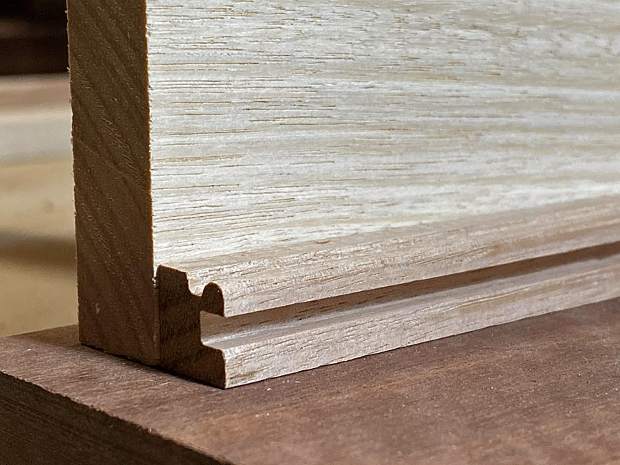
This is a mock up: the bead at the top and the groove on the side ...
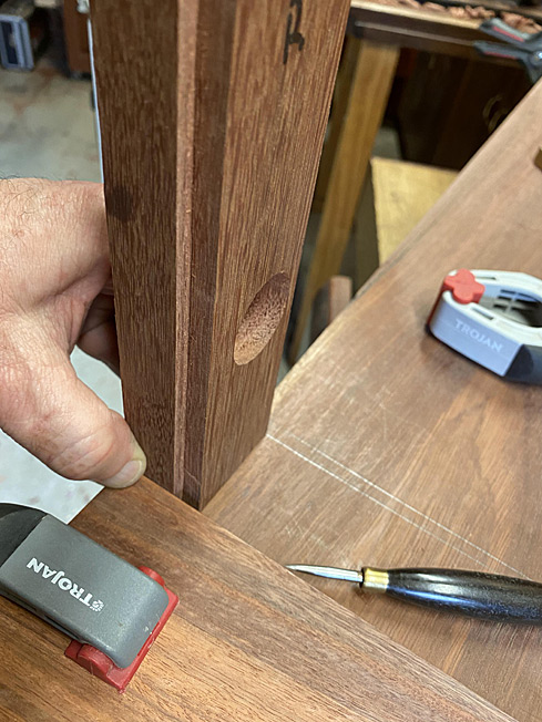
I have a strategy to fit the drawer fronts, so that the edges align with each other. It is all about accurate marking out. This will hinge on getting the opening exact, and transferring the respective measurements to their drawer fronts.
First order of the day was to fit (what will become) drawer backs to the front between the drawer dividers. This is what the result looked like ...
The table saw can cross cut really close, but only a shooting board will get the final dimension ...

On to the all-important drawer fronts!
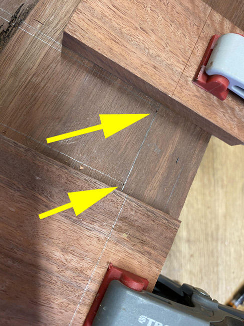
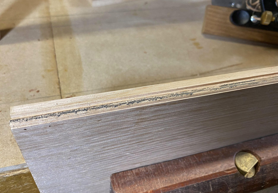
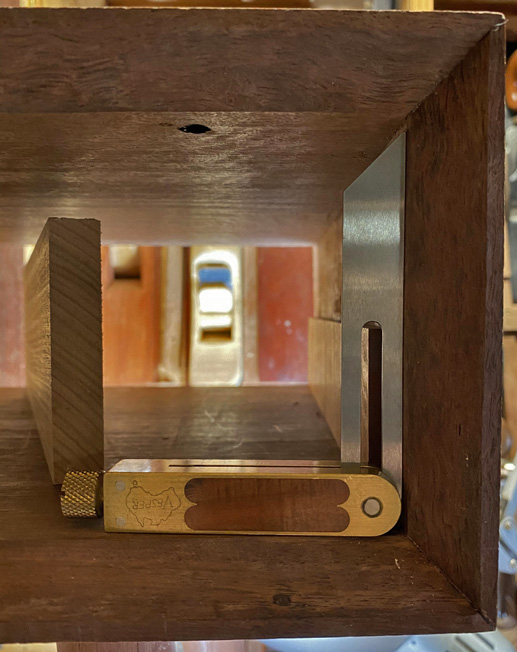
I was heartened that all the verticals were indeed vertical still ... well, except for one (if you look carefully, you will see light in the top half) ...

This meant a slight adjustment of that side .. again a job for the shooting board.
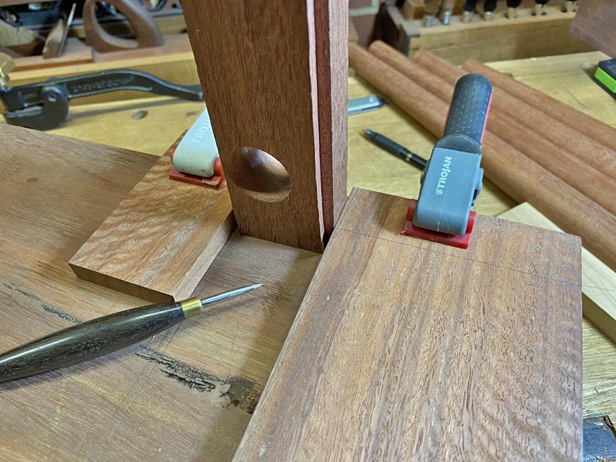
Set one, mark the angle with a small sliding bevel ...
... transfer this to the side of the board, and head for the shooting board. As the side is no longer square, a shim is used to create the needed angle ...
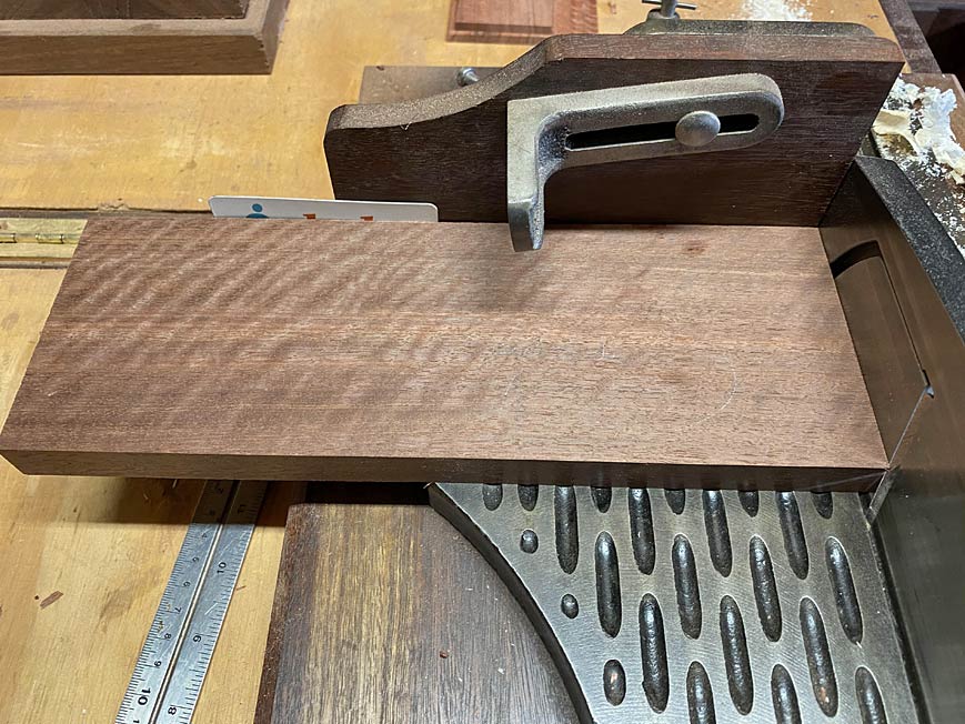
A good result ...

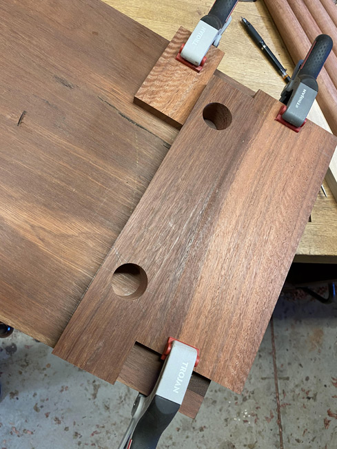
This is the join I need to manage ...
These are the fronts fitted in sequence ...

And here were are now, waiting for the next build day ...

Regards from Perth
DerekVisit www.inthewoodshop.com for tutorials on constructing handtools, handtool reviews, and my trials and tribulations with furniture builds.
-
24th February 2020, 04:23 PM #56
GOLD MEMBER
- Join Date
- Feb 2003
- Location
- back in Alberta for a while
- Age
- 68
- Posts
- 12,006
Hi Derek
Just a quick comment -- does your niece live in Perth or somewhere more humid like Sydney?
If it's not Perth, perhaps open up the clearances so the drawers don't stickregards from Alberta, Canada
ian
-
24th February 2020, 04:29 PM #57
Be inspired. Be creative. Be bold.
- Join Date
- Apr 2001
- Location
- Perth
- Posts
- 10,821
Hi Ian!
She is in Sydney. Having lived there myself (30+ years ago) I know how humid it gets!
The plan is to open up the clearances, especially at the top of the drawer fronts. These will be done later. I have made everything tight at this stage (as tight as possible) as this is needed for measuring and marking the rebates for the lipped dovetails. As you well know, it is always easier to remove wood that to put it back!
Regards from Perth
DerekVisit www.inthewoodshop.com for tutorials on constructing handtools, handtool reviews, and my trials and tribulations with furniture builds.
-
25th February 2020, 01:10 AM #58
Be inspired. Be creative. Be bold.
- Join Date
- Apr 2001
- Location
- Perth
- Posts
- 10,821
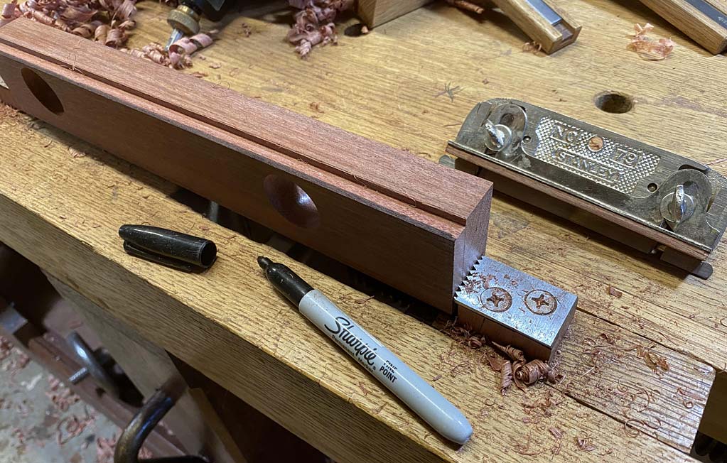
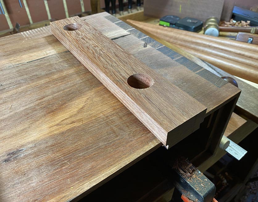
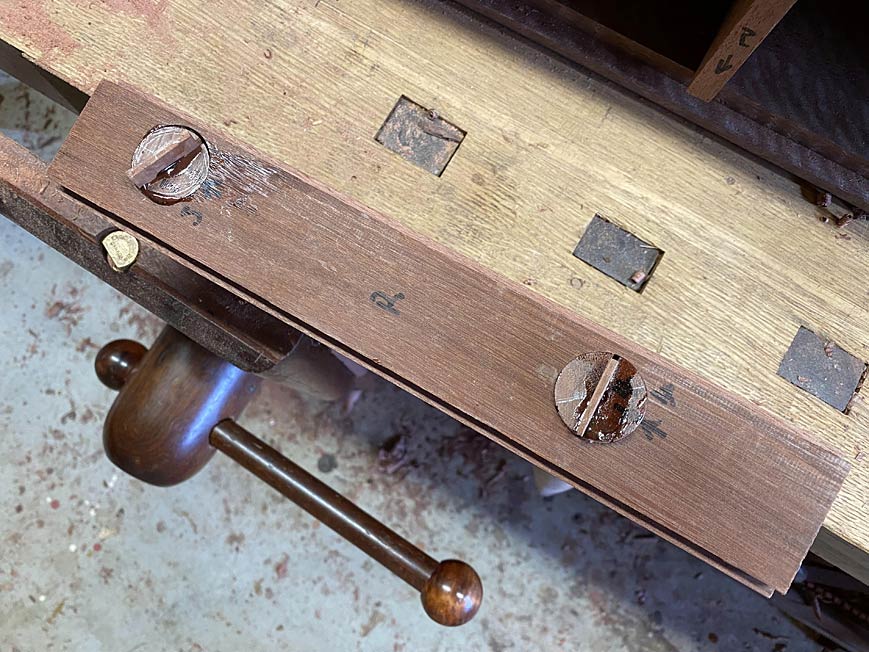
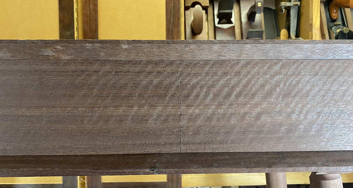
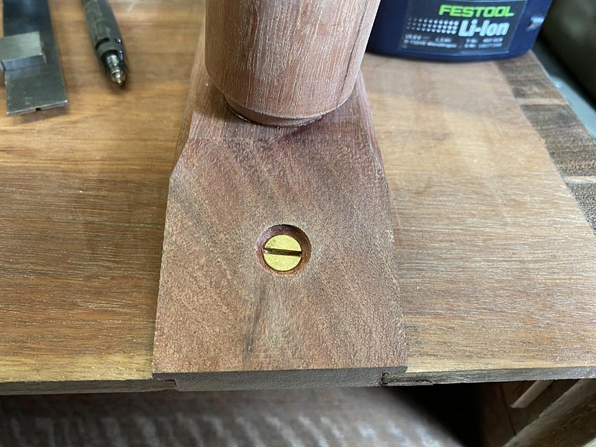
The process of attaching of the legs was completed by the addition of two screws in the sliding dovetail base.
Why add screws? The screws are not to prevent the base sliding back (an elongated hole actually encourages this). It is just to prevent the base twisting in, and breaking out of, the socket since there is no glue there to prevent any lateral movement.
The force comes from the splayed and angled legs. They will want to cant outward, and this becomes more so when the three drawers are filled and a vase of flowers is placed on the top of the table.
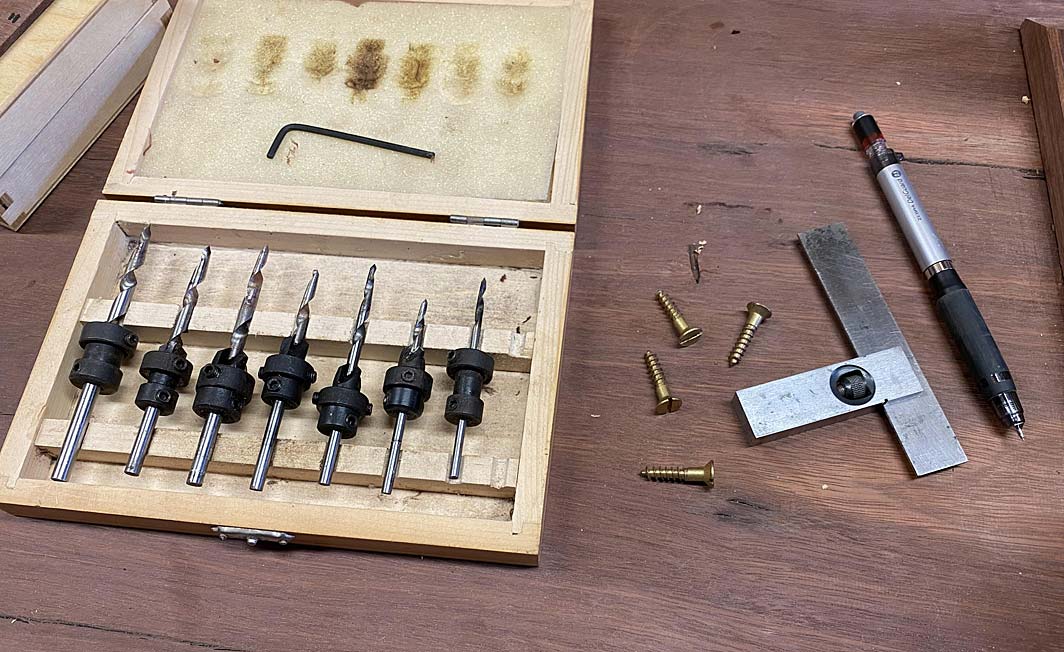
I thought that it is worth mentioning the screws used and how they were inserted.
The screws are 1" long brass tapered wood screws. The drill bits are also tapered to match. These ones include a countersink and depth stop.
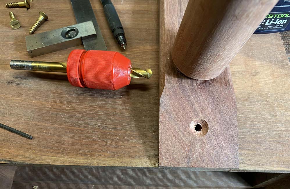
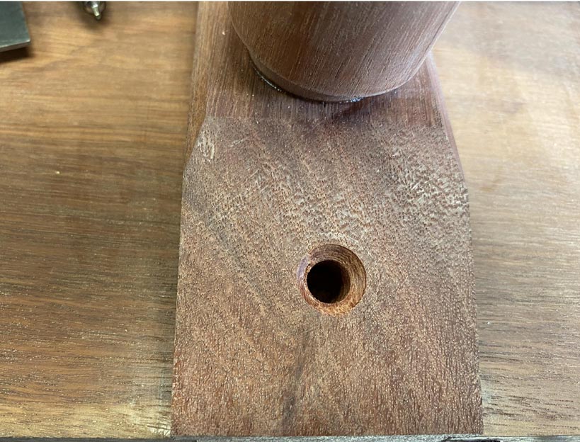
The plan is to drill the hole for the screw through the base and into the case, and then widen the hole in the base. This will permit the base to move with expansion and contraction. In this case 2mm each way.
A wider drill bit (and depth stop) ..
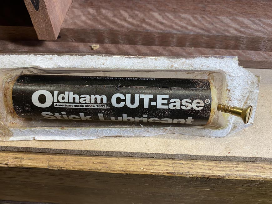
Before inserting a screw, especially brass screws, they are dipped in a little wax. This is wax for lubricating bandsaw blades ...
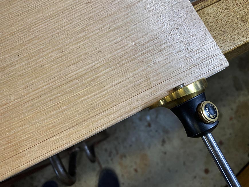
Here is the widened hole ...
The gap around the screw ...
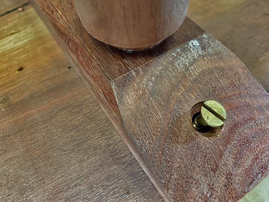
The second screw is on the other side of the leg. This is positioned about half way between the end screw and the glued toe.
Regards from Perth
DerekVisit www.inthewoodshop.com for tutorials on constructing handtools, handtool reviews, and my trials and tribulations with furniture builds.
-
25th February 2020, 12:47 PM #59
Senior Member
- Join Date
- Sep 2018
- Location
- Tasmania
- Age
- 53
- Posts
- 186
Looking really nice, Derek. I'm learning things along the way with your build and commentary, thank you.
Just a quick question, are those the Carbatec tapered drill bits/countersink? How do you find them?
Regards Adam
-
25th February 2020, 02:54 PM #60
Be inspired. Be creative. Be bold.
- Join Date
- Apr 2001
- Location
- Perth
- Posts
- 10,821
Adam, I think that I did purchase them from Carbatec, possibly about 15 or 20 years ago. They work OK.
The choice of screw came up, and I have been pondering on this. I must admit that I chose the screw first as a wood screw and that it could be recessed out of sight. My thoughts were on a wider hole for movement, and did not consider whether the conical countersink would limit movement. The answer is "I don't know" whether it will do so. To be safe, I plan to swap out the screws for round heads, and shape the countersink into a flat (using a wider forstner bit)
Regards from Perth
DerekVisit www.inthewoodshop.com for tutorials on constructing handtools, handtool reviews, and my trials and tribulations with furniture builds.


 Reply With Quote


Similar Threads
-
Entry Hall Mirror - WIP
By Rookie in forum WOODWORK - GENERALReplies: 5Last Post: 31st August 2010, 11:12 PM -
A gift for my Niece's 21st ... ssshhh don't tell her!
By Touchwood in forum BANDSAWN BOXESReplies: 10Last Post: 22nd November 2009, 11:13 AM -
hall table, wine table, water stone box
By driftit in forum WOODWORK - GENERALReplies: 6Last Post: 1st May 2009, 11:20 PM -
Project 1 - Entry Way Table
By `Felix` in forum WOODWORK PICSReplies: 13Last Post: 25th March 2004, 03:54 PM
