

 Thanks:
  Likes:
  Needs Pictures: 0
 Picture(s) thanks:
Results 61 to 75 of 88
Thread: Entry hall table for a niece
-
25th February 2020, 09:49 PM #61
 GOLD MEMBER


- Join Date
- Aug 2004
- Location
- Perth WA
- Posts
- 2,035

Such a simple thing made to look complicated.
Experienced in removing the tree from the furniture
-
25th February 2020 09:49 PM # ADSGoogle Adsense Advertisement
- Join Date
- Always
- Location
- Advertising world
- Posts
- Many
-
26th February 2020, 12:23 AM #62
Be inspired. Be creative. Be bold.
- Join Date
- Apr 2001
- Location
- Perth
- Posts
- 10,821
Okay, so I decided that the wood screws were a mistake. They would prevent movement rather than permit it. So they had to go.
This is the exchange screw: a 12 gauge stainless steel wood/metal screw with an all-important flat/domed head.
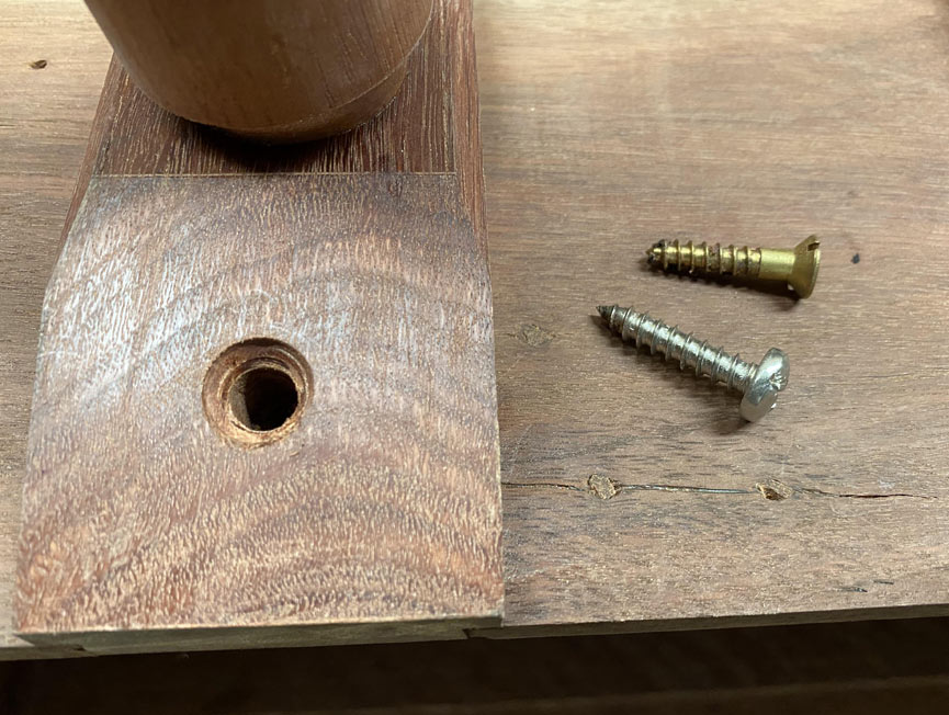
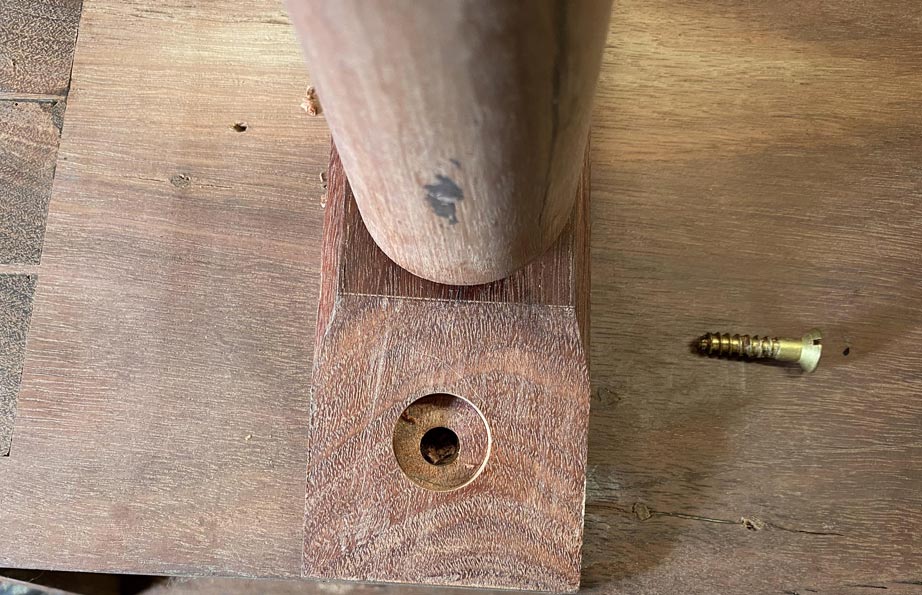
The plan was to use a 3/4" forstner bit. This would leave a wide, flat area for the screw head to move along. The range of movement would be the same as before, about 2mm each side of the screw.
A MDF template was made to guide the forstner bit, as it had no support in view of the existing hole ...
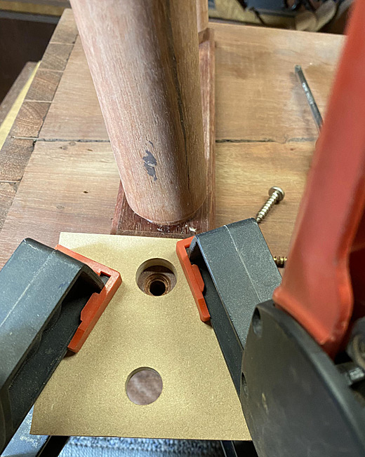
Drilled to depth ...
A steel washer added ...
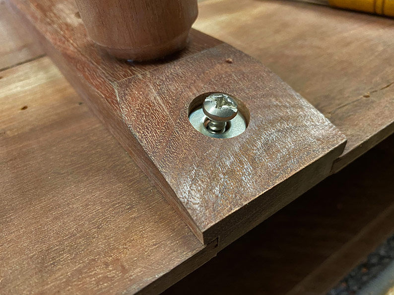
Done ...
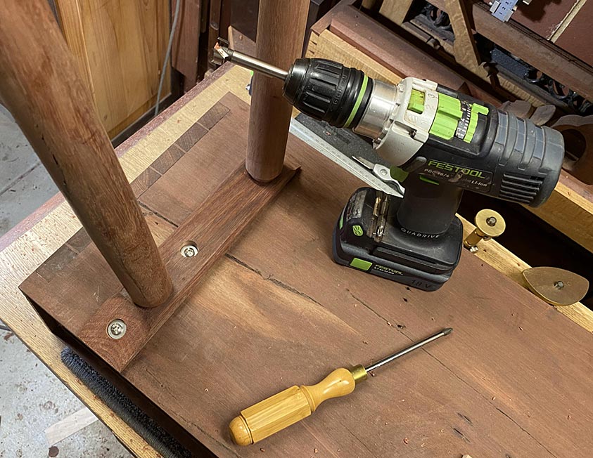
I had only 15 minutes after work today, but on the weekend, when I get back to this build, I plan to add a third screw behind the front leg.
Regards from Perth
DerekVisit www.inthewoodshop.com for tutorials on constructing handtools, handtool reviews, and my trials and tribulations with furniture builds.
-
27th February 2020, 12:58 AM #63
Be inspired. Be creative. Be bold.
- Join Date
- Apr 2001
- Location
- Perth
- Posts
- 10,821
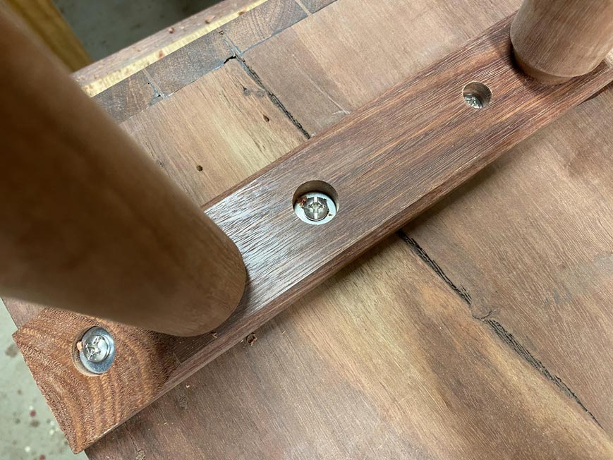
I put the last screws in after work. That will free up this weekend to concentrate on building the drawers.
There are three screws. The one at the toe is fixed and there is no play for any movement. The two at the rear can slide 2mm each way.
Regards from Perth
DerekVisit www.inthewoodshop.com for tutorials on constructing handtools, handtool reviews, and my trials and tribulations with furniture builds.
-
27th February 2020, 12:59 AM #64
Be inspired. Be creative. Be bold.
- Join Date
- Apr 2001
- Location
- Perth
- Posts
- 10,821
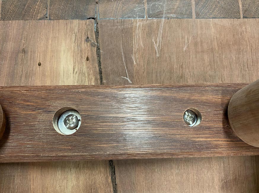
I put the last screws in after work. That will free up this weekend to concentrate on building the drawers.
There are three screws. The one at the toe is fixed and there is no play for any movement. The two at the rear can slide 2mm each way.
Regards from Perth
DerekVisit www.inthewoodshop.com for tutorials on constructing handtools, handtool reviews, and my trials and tribulations with furniture builds.
-
27th February 2020, 01:18 AM #65
Be inspired. Be creative. Be bold.
- Join Date
- Apr 2001
- Location
- Perth
- Posts
- 10,821
Rod, actually, this is very complicated. Originally Posted by rod1949

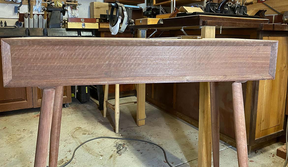
It is not about drilling for screws. That would be simplistic. It is about mechanical design, that is, how to strengthen the base.
There is the leverage placed on the base by the legs, because they angle away from the base. Since the legs are very firmly attached to the base, if the legs twist (which is the threat imposed by weight on the table top) they lever the base along with them. While the base is attached with a sliding dovetail, if enough force is applied to it, it could break out sideways (laterally). The screws are to prevent the base twisting over. The base is still free to move along the sliding dovetail (longitudinally), just not free to move laterally.
Regards from Perth
DerekVisit www.inthewoodshop.com for tutorials on constructing handtools, handtool reviews, and my trials and tribulations with furniture builds.
-
2nd March 2020, 03:54 AM #66
Be inspired. Be creative. Be bold.
- Join Date
- Apr 2001
- Location
- Perth
- Posts
- 10,821
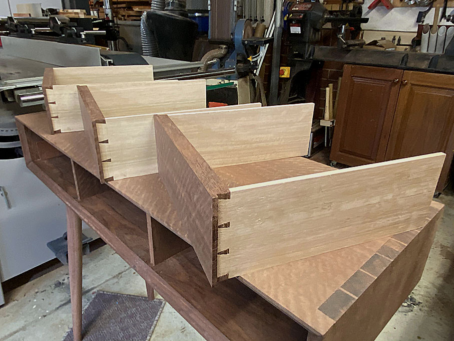
This is the part where we begin building one-piece lipped drawers (as contrasted with applied fronts).
In preparing for this part of the build, my research uncovered exactly one article on dovetailing lipped drawer fronts. This is by Christian Becksvoort in Fine Woodworking magazine (#263-Sep/Oct 2017 Issue). Interesting that.
Why lipped drawer fronts? Simply because the three drawers must run continuously across the front, without a gap between them.
The lipped sides will wrap around the drawer dividers, and these will double as drawer stops. This will be illustrated in a short while.
The lipped ends create a challenge to form the pins/sockets for the tailed drawer sides since it becomes difficult to saw. I have a novel solution
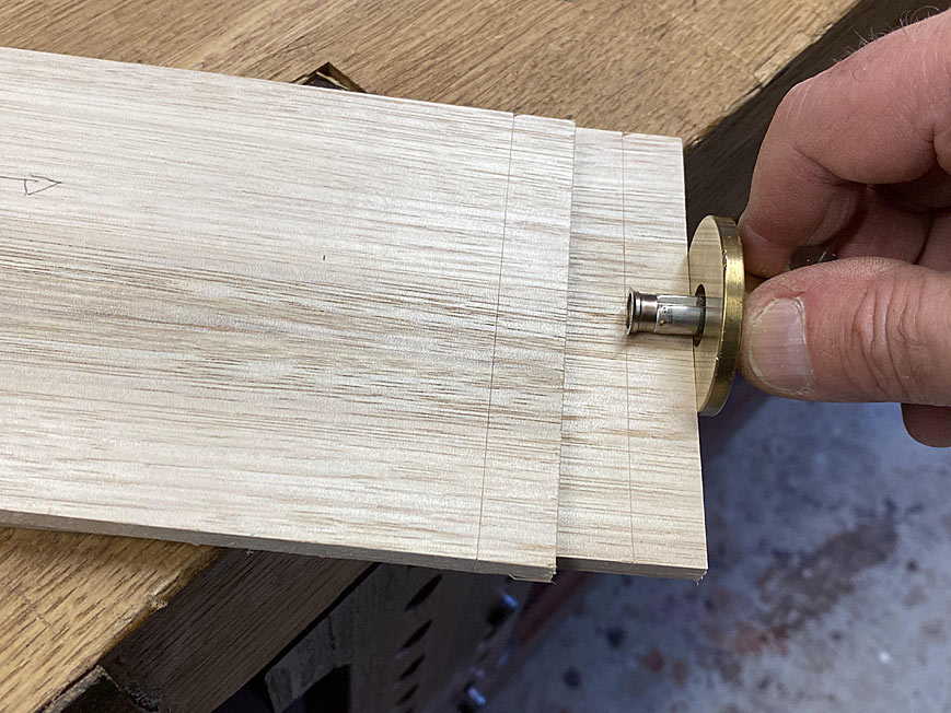
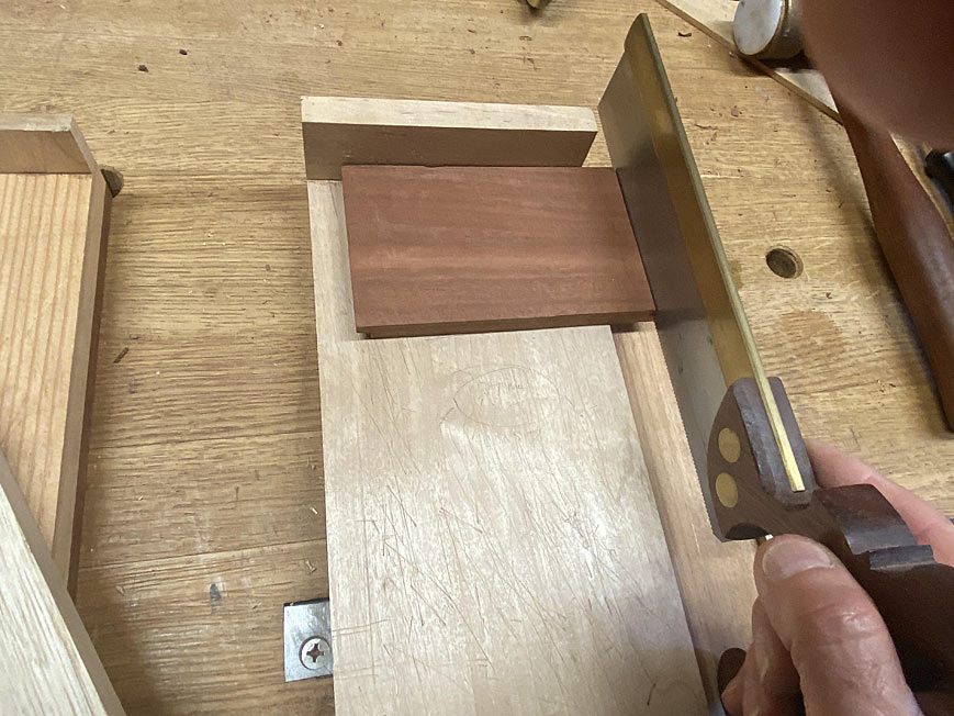
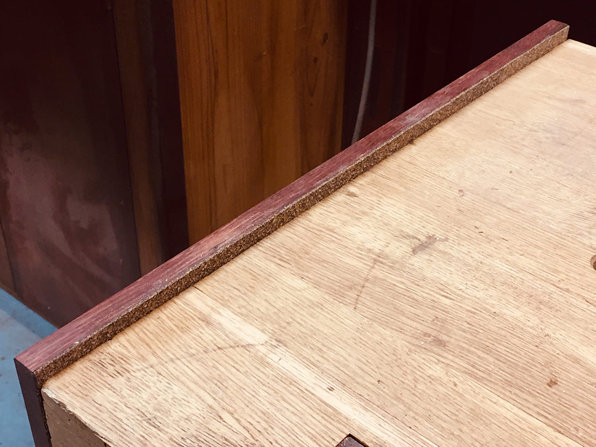
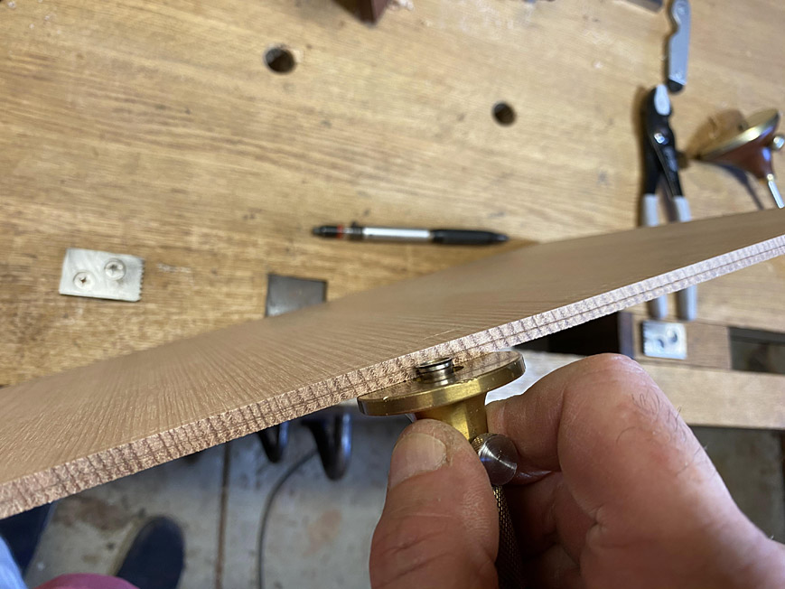
We begin by marking where the lipped sides will be. This is knifed in through from the rear of the case ...
The marks are knifed with a cutting gauge.
The distance from the edge is exactly the same for each board - 6mm. The side spacers are 6mm wide and the two central drawer dividers are 12mm thick, of which each lip is half this thickness.
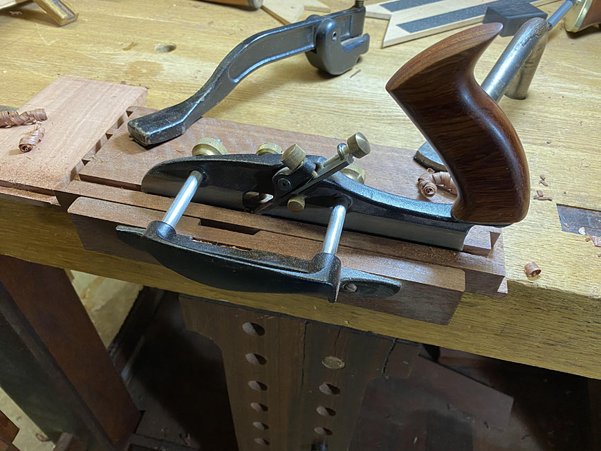
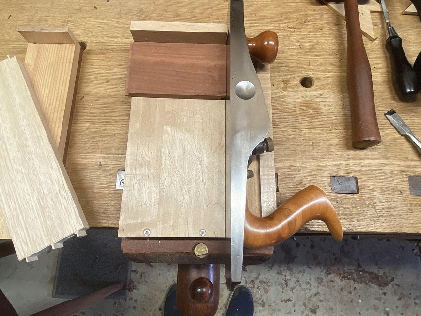
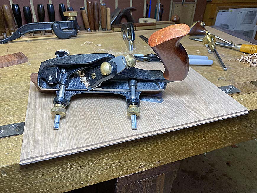
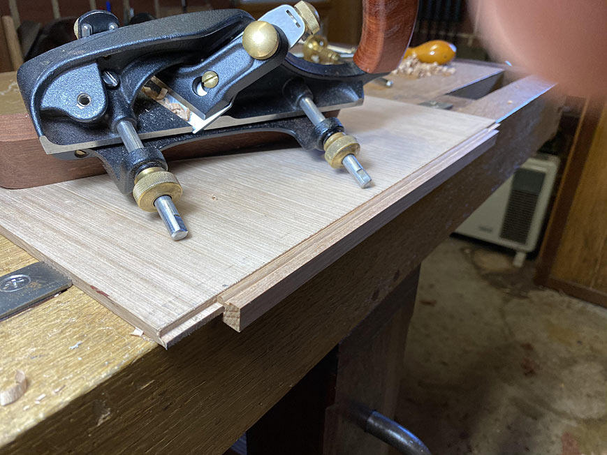
The drawer front is rebated with a moving filletster plane ...
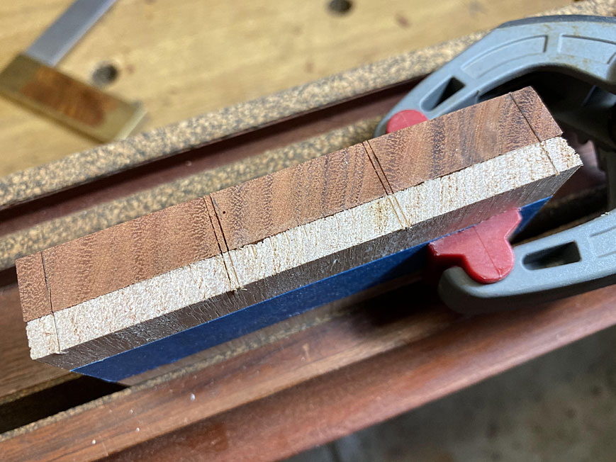
With both sides rebated, the centre must fit snuggly between the drawer dividers ...
... and leave exactly half of the dividers remaining ...
Side-by-side, perfect fit ...
The rebates are fine-tuned with a cutting gauge, ensuring that they are even and square ...
This measure is transferred to the drawer side ...
I took the time to lay out the dovetails on a scrap as a template. This saves a lot of repeated layouts ...
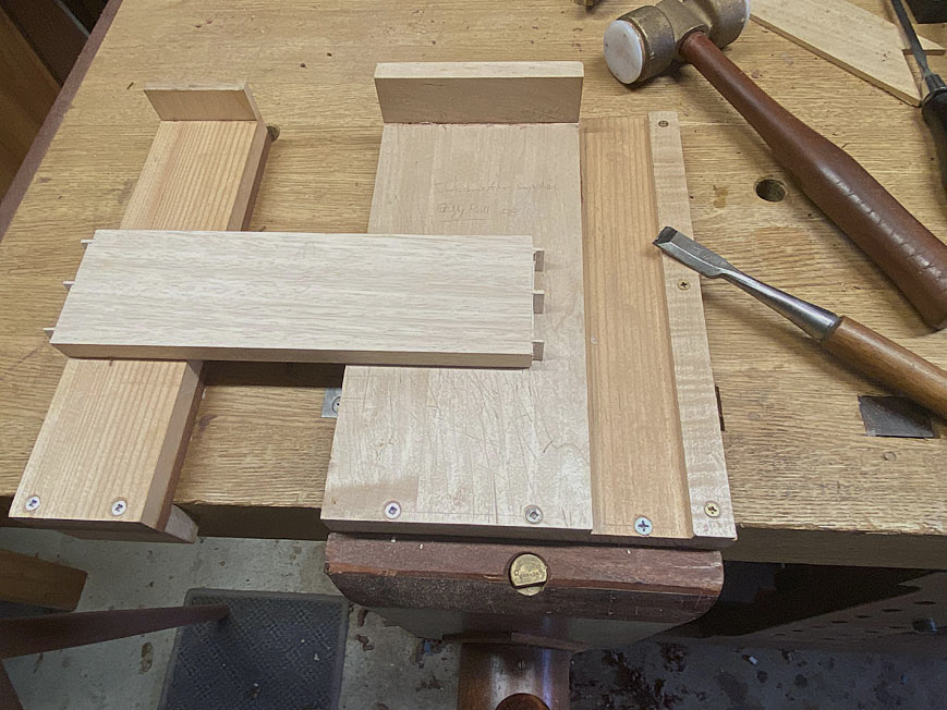
Tails done ...
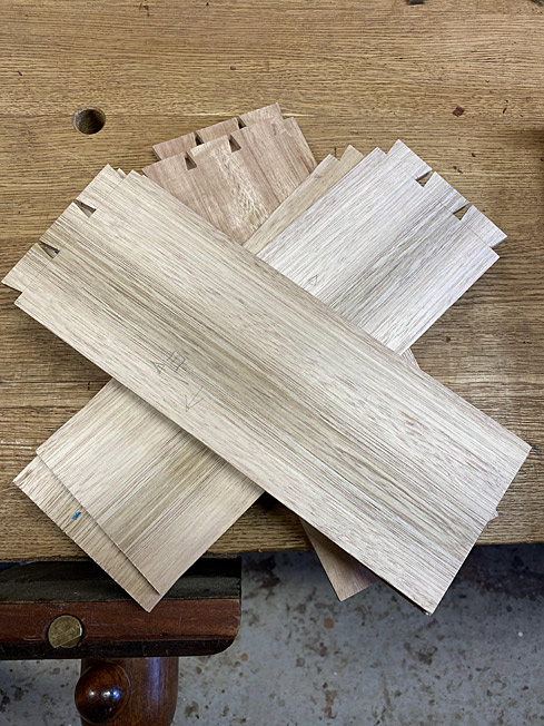
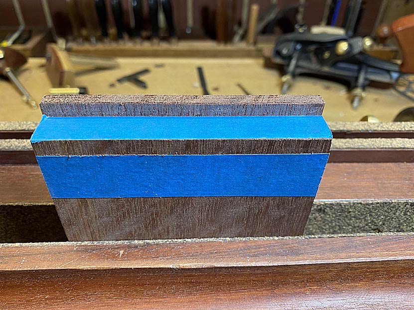
The tail board with be placed here, but with the lip extending past ...
This is what it would look like if dovetailed ...

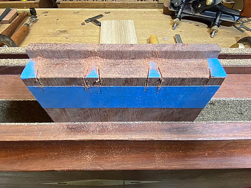
To make it easier to see what I am sawing, I am using blue tape ...
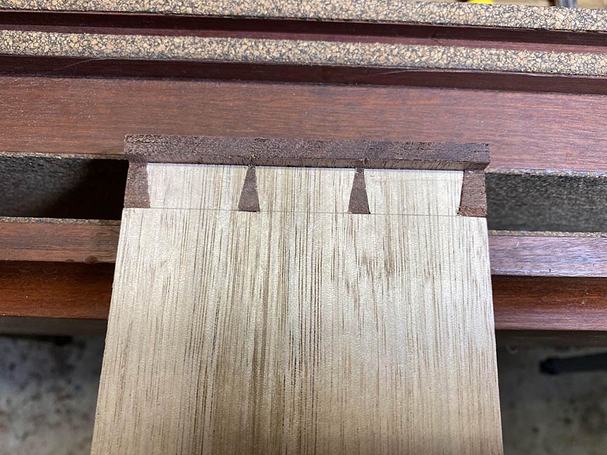
Transferring the tails to the pin board is made a little easier as the rebate is a handy stop ..
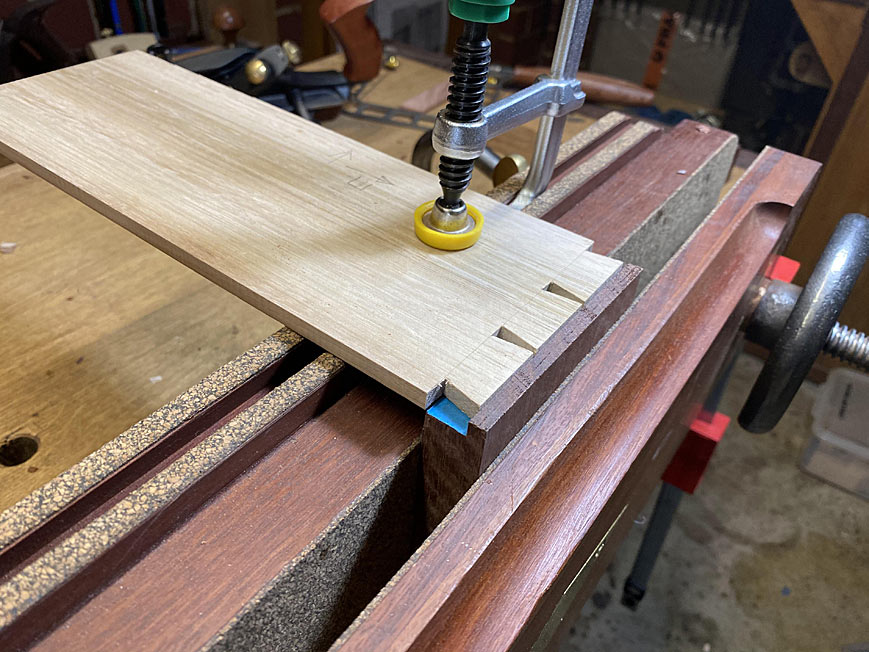
Marked out produces this ...
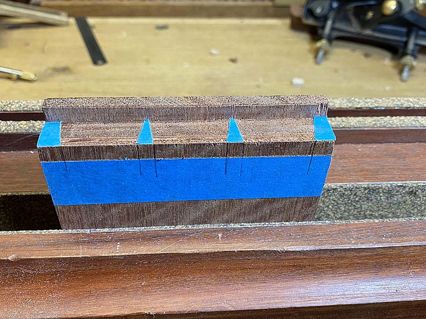
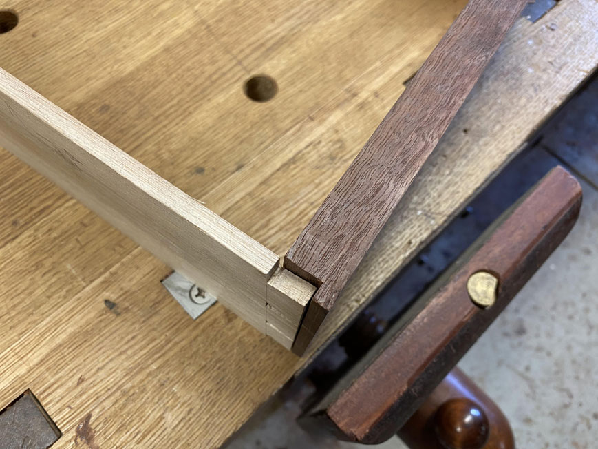
And that is where it stops being straight forward as this is as much as it is possible to saw inside the lines ...
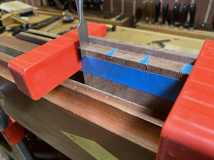
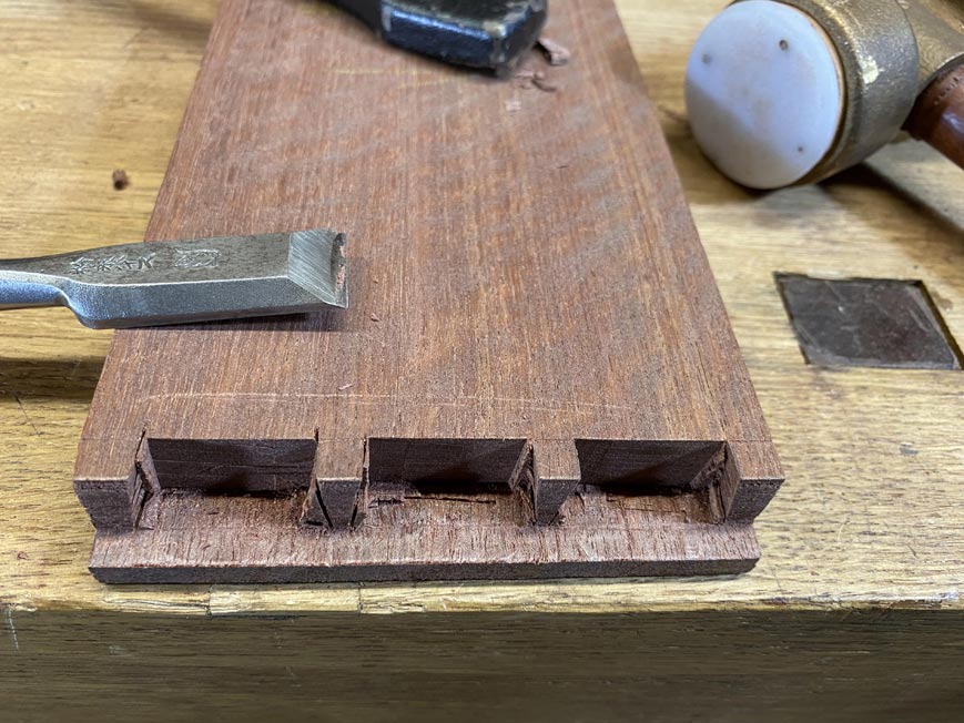
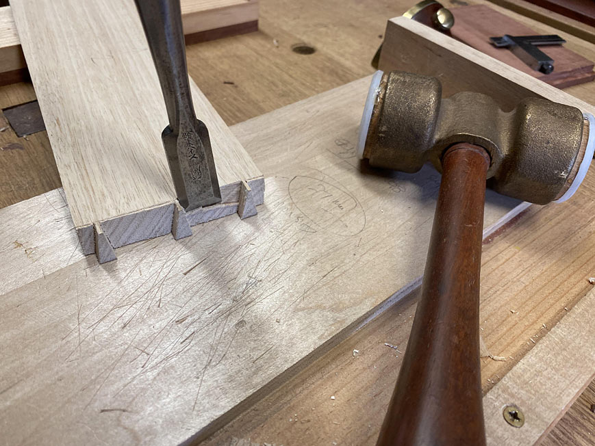
I decided that, if I could not saw it, I would chop it. This gives new meaning to "chopping dovetails"
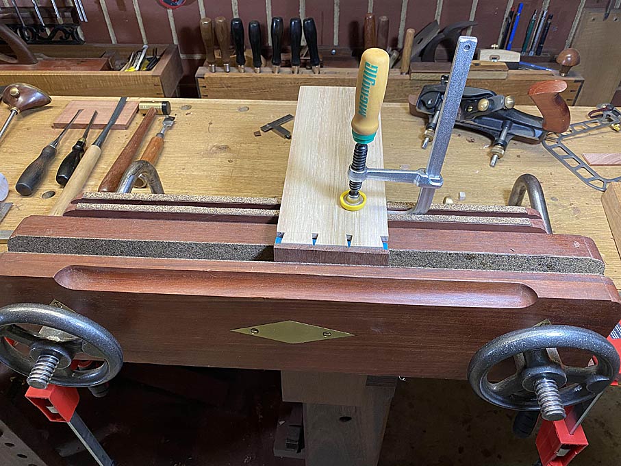
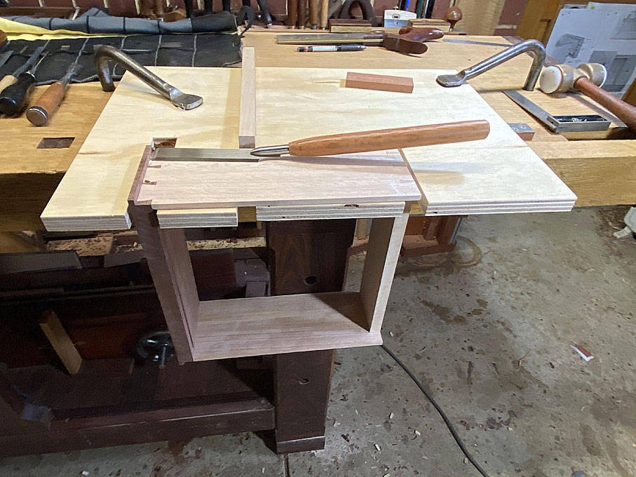
The pin board is clamped (to avoid any splitting), and the kerfing chisel is used to deepen the existing half-kerf, and then extend it across the socket ...
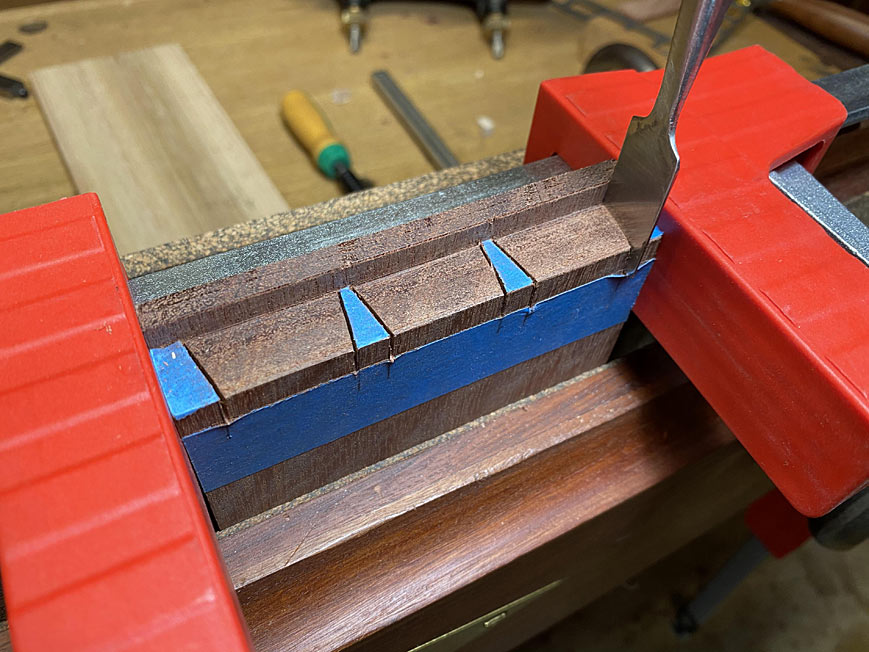
Now the waste is chopped out ...
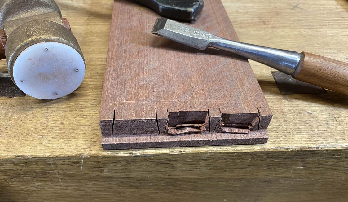
This picture of a fishtail chisel cleaning the corner of the socket is for bill
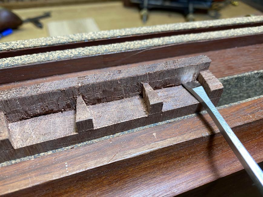
Does it fit? Oh, the suspense!
Two more to go.
Regards from Perth
DerekVisit www.inthewoodshop.com for tutorials on constructing handtools, handtool reviews, and my trials and tribulations with furniture builds.
-
3rd March 2020, 03:05 AM #67
Be inspired. Be creative. Be bold.
- Join Date
- Apr 2001
- Location
- Perth
- Posts
- 10,821
Today I completed the second and third drawer fronts ...
 Since I had only come across one article on making the lipped drawers - and that predominantly used power tools - and failed to find a single video on the topic, I decided to make one myself:
This is a real-time video - no editing. So skip the parts as they bore you. Hopefully some of it will amuse. Or watch at bedtime if you are insomniac Regards from PerthDerek
Visit www.inthewoodshop.com for tutorials on constructing handtools, handtool reviews, and my trials and tribulations with furniture builds.
Since I had only come across one article on making the lipped drawers - and that predominantly used power tools - and failed to find a single video on the topic, I decided to make one myself:
This is a real-time video - no editing. So skip the parts as they bore you. Hopefully some of it will amuse. Or watch at bedtime if you are insomniac Regards from PerthDerek
Visit www.inthewoodshop.com for tutorials on constructing handtools, handtool reviews, and my trials and tribulations with furniture builds.
-
8th March 2020, 05:28 AM #68
Be inspired. Be creative. Be bold.
- Join Date
- Apr 2001
- Location
- Perth
- Posts
- 10,821
The build is nearing the conclusion. The drawers, case back, and finish to do. Here, the drawers are continued. The focus of this article is on fitting the drawer (with lipped sides), and the fixtures that are used in the course of this process.
We ended the last build session with the drawer parts made ...

... and the lipped drawer fronts completed ...

First task today was to plane the groove for the drawer fronts ..
The drawer sides and drawer back were dovetailed ... simple through dovetails. The notable feature here is that space is left for the drawer slip (which replaces the drawer groove as the drawer sides are 1/4" thick).
Of interest may be the bench hook I use. I suspect that some may look at this and wonder why I am butchering it by chopping on its top ..
Well, it is just scrap, and took about 5 minutes to make. So far this one has lasted about 3 months. I should get a few more out of it.
Not only is it used for chopping, but also sawing ...
... and even shooting ...
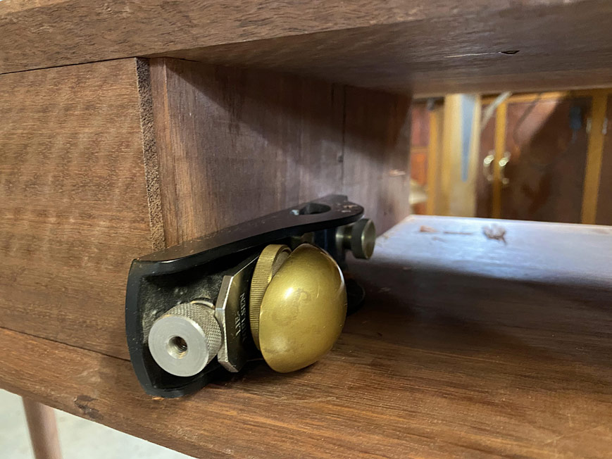
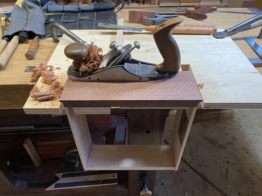
One of the issues with a lipped front is that it cannot be planed to fit after glue up. So, there are lots of dry fitting, and the sides are planed individually. This planing stop is invaluable for thin boards ...
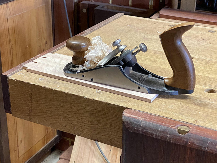
There is non-slip in the form of Crubber on the face of the stop ...
When fitted together, any raised pins need to be pared level. Here, the drawer is captured in a fixture (essentially, two pieces of ply, each with a cut out). The pins are pared with the newly-released Veritas flushing chisels ...
I've had a pre-production set for a couple of years. This is what a prototype handle looks like ...
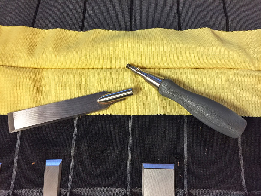
Veritas now supply this in a nice wooden handle. The one I am using is a design of my own, ala a Japanese slick ..

Fitting the drawers also required positioning and glueing the drawer dividers. These also act as drawer stops ...
This is the drawer divider in position ...
It is slid back ...
The first third of the dado receives glue ...
The drawer is replaced and positioned ..
And then the drawer divider is slid up against the rear of the lip ..
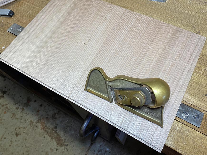
The drawer case is fine-tuned with the LN Rabbet Block Plane ...
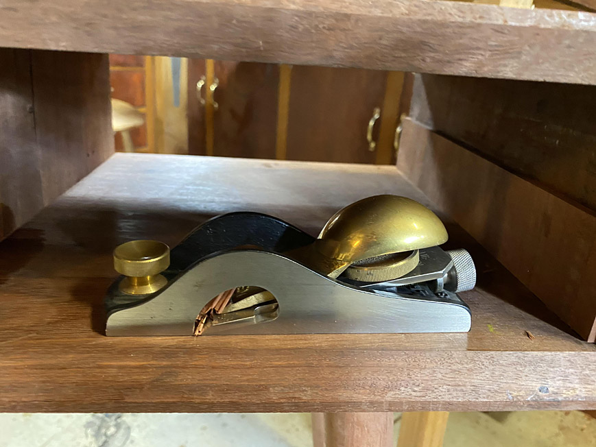
This is used to smooth over any irregularities in the side walls and, where necessary, to plane away any fat ...
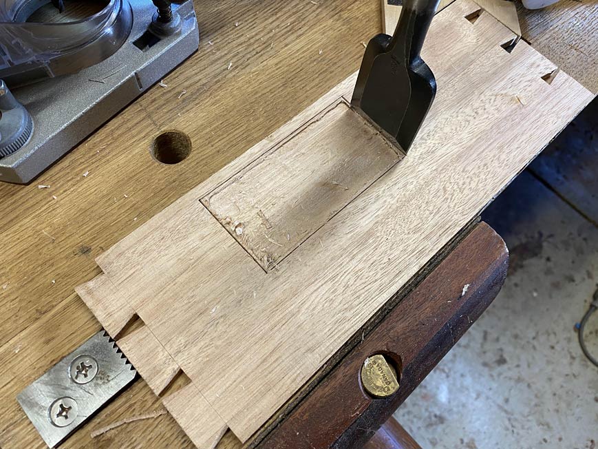
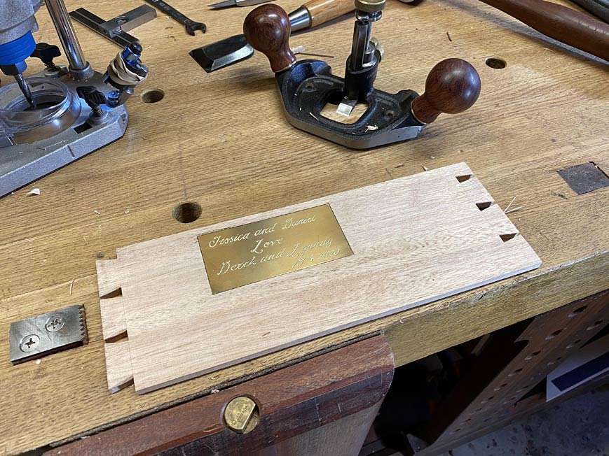
The drawers are in the process of being glued up. Drawer #3 cannot be glued up until a brass plate is recessed into one side. T
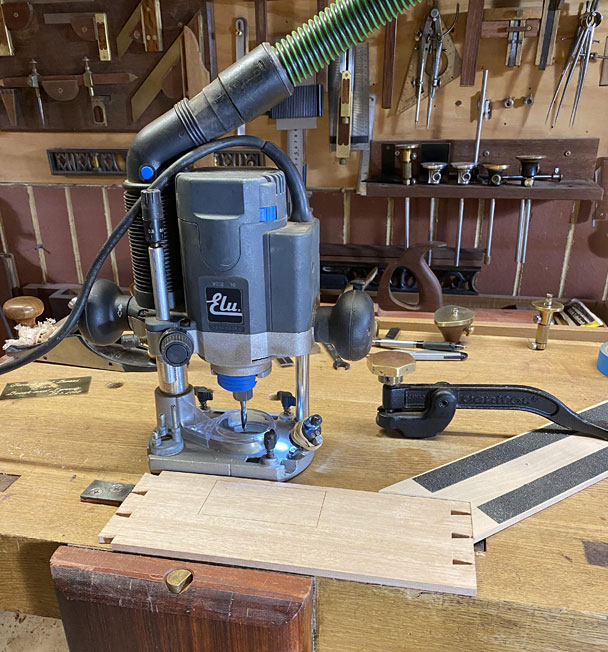
Marked out, the waste routed, and then chiselled along the circumference ...
The drawer fronts are planed ...
Another dry assembly and check for fit ...
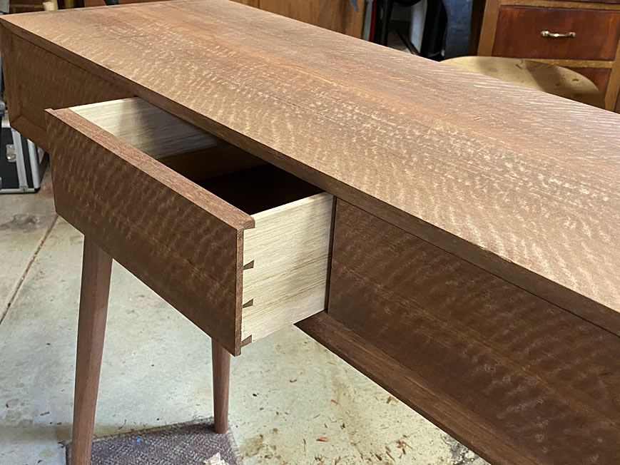
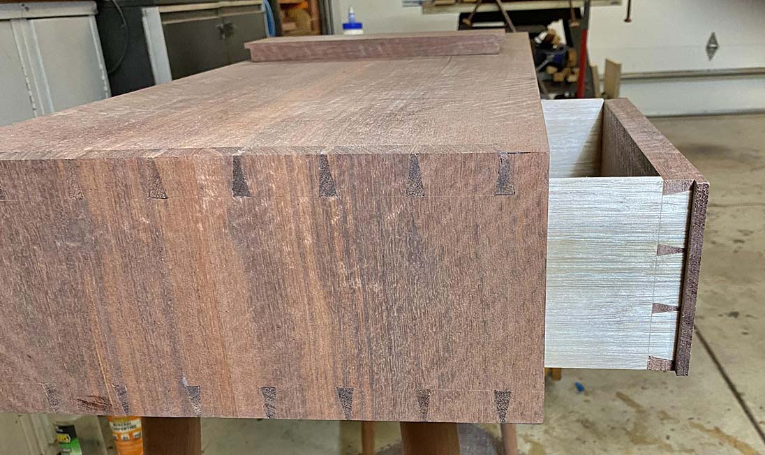
If there is any resistance to the drawer being pushed in-and-out, I test fit it from the rear. This shows whether the drawer or case needs some planing. Looking good here, as it goes right in ...
There is good drawer extension (about 80%) ...
The drawers are now glued up.
Lastly, for the day, the slips are attached. These began like this, grooved and beaded ...
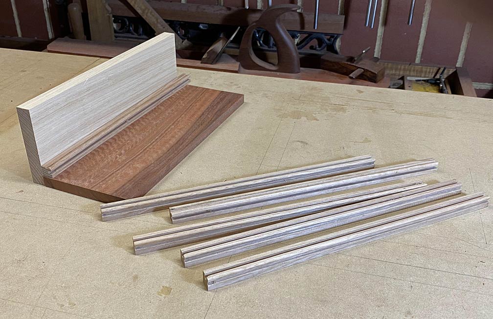
A Jarrah runner is added below. The upper section of the slip is, as with the drawer sides and drawer bottoms, made from Tasmanian Oak. This is similar to US White Oak in hardness and wear. Since the drawers run on Jarrah, the wear properties are improved with the Jarrah wear section ...
Tomorrow should see the conclusion of the build.
Regards from Perth
DerekVisit www.inthewoodshop.com for tutorials on constructing handtools, handtool reviews, and my trials and tribulations with furniture builds.
-
8th March 2020, 09:14 PM #69
GOLD MEMBER
- Join Date
- Oct 2013
- Location
- Perth, Australia
- Posts
- 1,813
Thanks as always for the detailed explanations, it's looking fantastic! What sort of finish will it receive?
You have one more YouTube subscriber as well, going to watch later on this evening [emoji846]
-
9th March 2020, 11:02 AM #70
GOLD MEMBER
- Join Date
- May 2007
- Location
- Sth Gippsland Vic
- Posts
- 4,389
derek.jpg
Why do you do a drawer slip like this Derek ? The gap from the slip slot down to the back ?
Does it mean the bottom will get a strip added?
I saw it in another thing you did a while back as well.
Rob
-
10th March 2020, 03:03 AM #71
Be inspired. Be creative. Be bold.
- Join Date
- Apr 2001
- Location
- Perth
- Posts
- 10,821
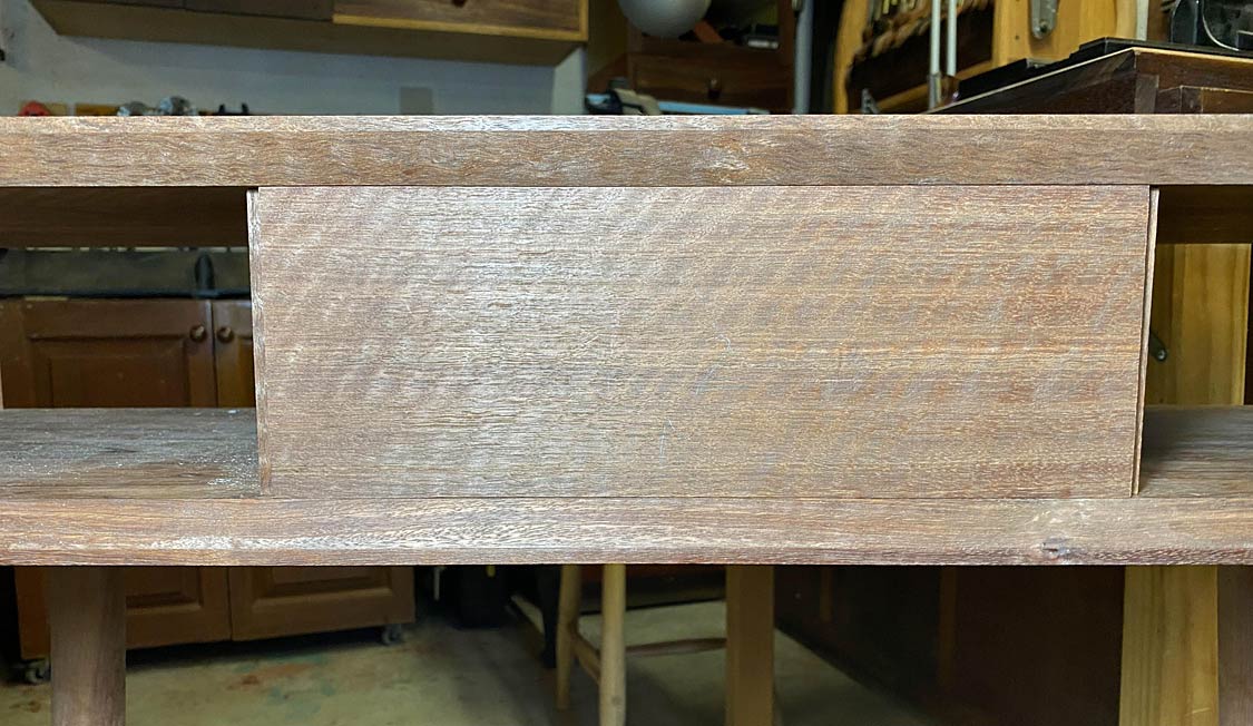
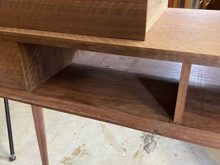
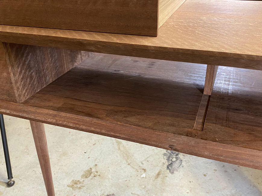
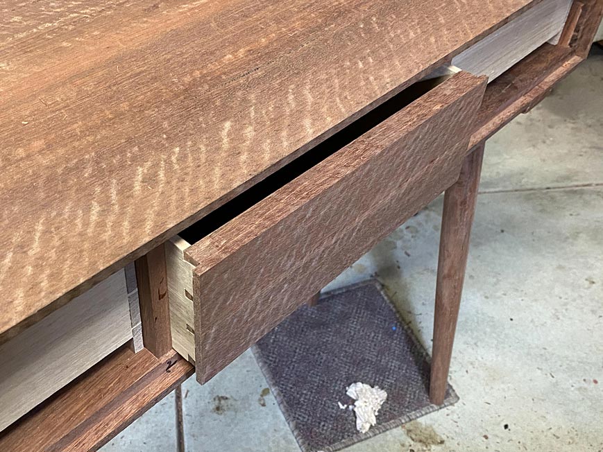
Rob, it is decorative, but also serves to meld together the slip with the drawer bottom where, although both are the same Tasmanian Oak, their grains run in different directions. This would look unsightly without something between them.
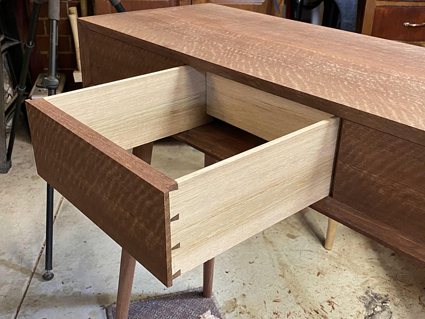
The quirk was a little wider here than I planned, but I am not going to change it now. The drawer will look similar to this ...


Regards from Perth
DerekVisit www.inthewoodshop.com for tutorials on constructing handtools, handtool reviews, and my trials and tribulations with furniture builds.
-
10th March 2020, 05:52 AM #72
GOLD MEMBER
- Join Date
- May 2007
- Location
- Sth Gippsland Vic
- Posts
- 4,389
Sorry Derek , I forgot to mention in my last post to look at the two red arrows I added showing what I meant . They are small and the photo needs enlarging to see them .
A drawer back normally meets the top of the slot in a slip or in a slot done in a drawer side where there is no slip . So when a slip is used the top part of it needs cutting off to form a step going under the back .
If it’s not there then your bottom will have a slight gap left and right and the rest will flex up to meet the drawer back in between the left and right side .
Or you could add a thin strip along the drawer bottom at the back that copies the top mould of your slip and your drawers have the feature of the top slip mould running down the left and right side and across the back to make up for the gap .
Rob
-
10th March 2020, 03:26 PM #73
Be inspired. Be creative. Be bold.
- Join Date
- Apr 2001
- Location
- Perth
- Posts
- 10,821
Hi Rob
I get it now
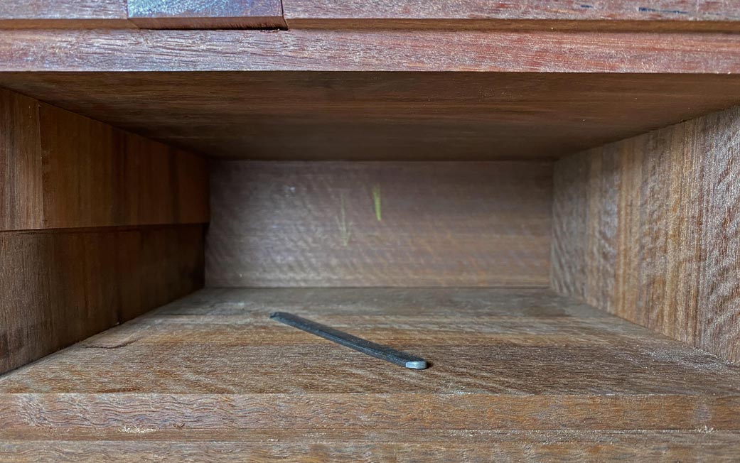
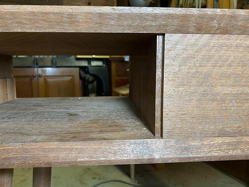
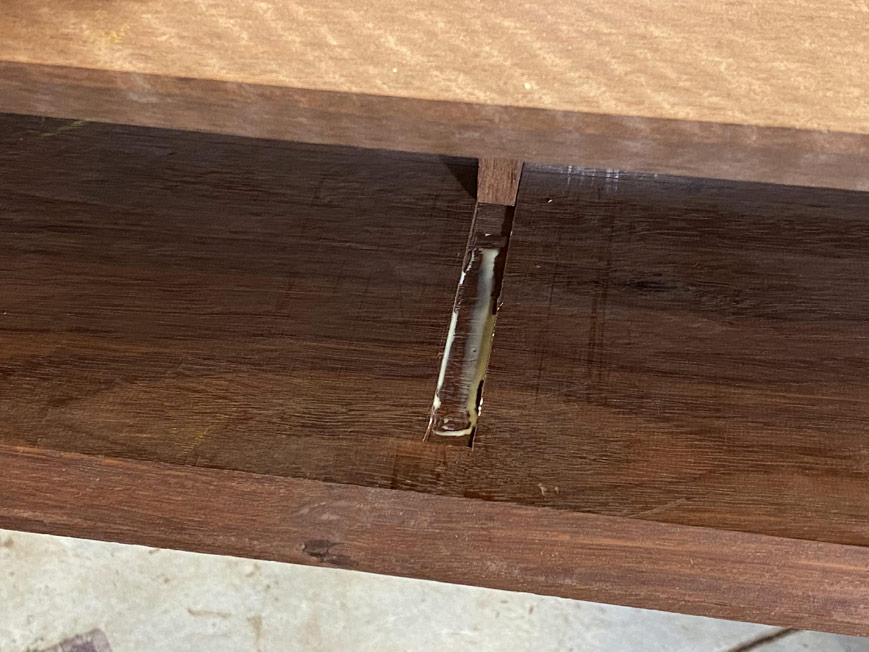
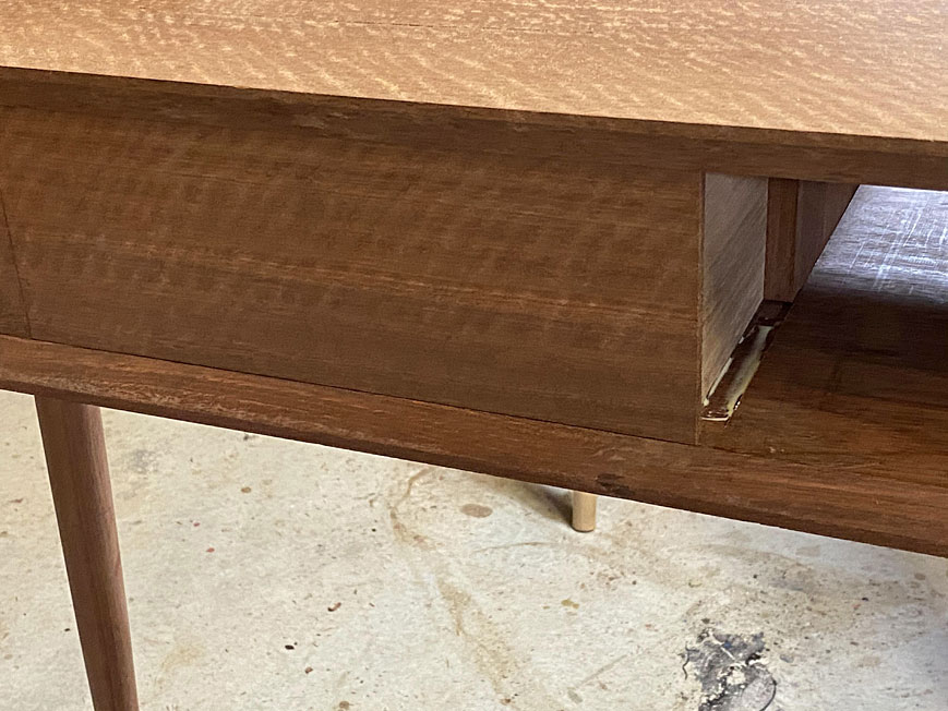
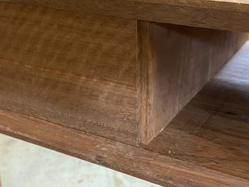
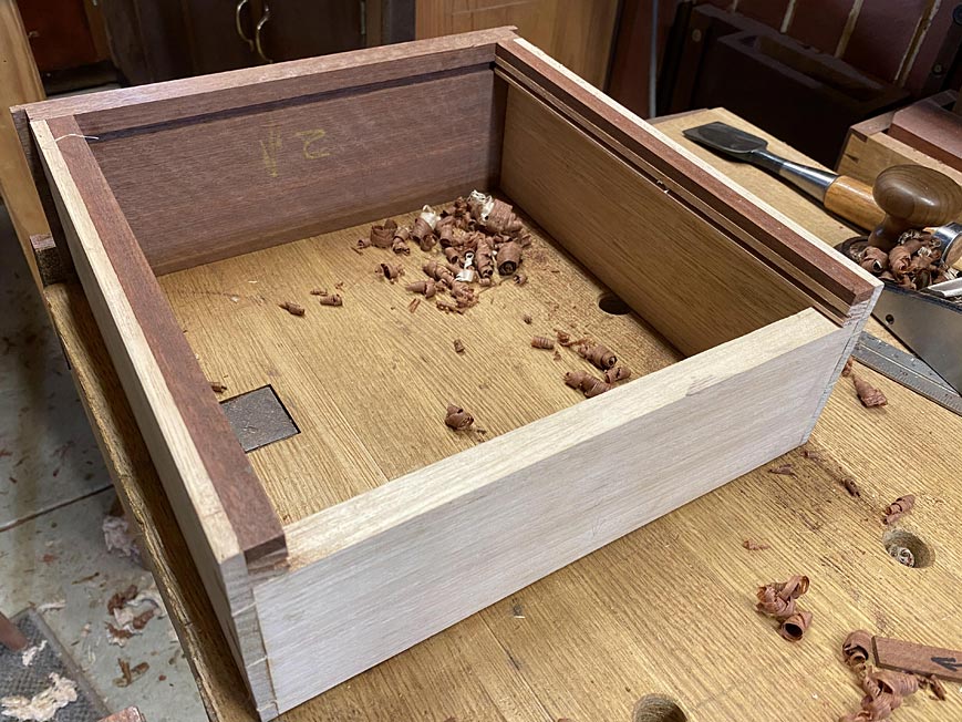
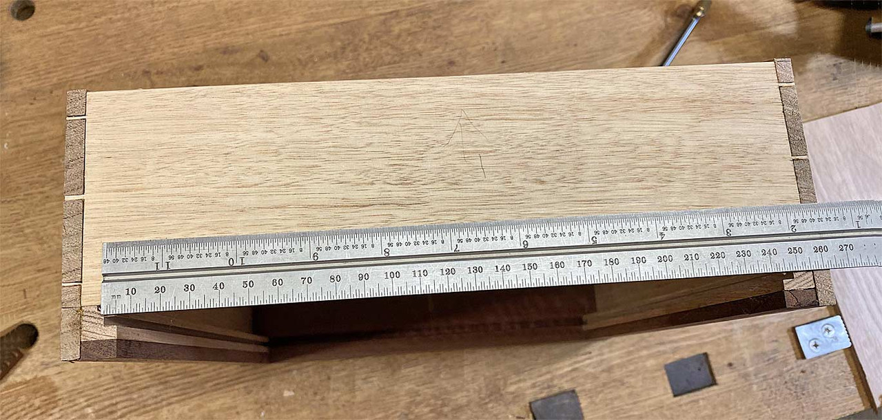
I have just one relevant photo on file, taken Sunday afternoon when completing the drawers. This shows a drawer bottom from the rear. It has not yet been pushed into the front groove (as it was, at that stage, to be finished in Ubeaut hard white shellac before insertion). Also, the underside of the drawer would be screwed to the underside of the rear drawer panel. This would tighten any tolerances.
At this stage, there is no light showing ...
Does that answer your question? I'll post more photos when the finishing is completed.
Regards from Perth
DerekVisit www.inthewoodshop.com for tutorials on constructing handtools, handtool reviews, and my trials and tribulations with furniture builds.
-
10th March 2020, 05:18 PM #74
GOLD MEMBER
- Join Date
- May 2007
- Location
- Sth Gippsland Vic
- Posts
- 4,389
Ahhh
Solved . Your rebating the bottom that way ! OK , different that’s for sure but it works . Looks interesting . It’ll have me thinking for the benefits of doing it that way . Me and most of the rest of the world probably do it the other side . I like to bevel but sometimes just run a rebate . I suppose you can have a thicker bottom and not lose space under the bottom for the drawer stops if you were using them there . But if you have a top rebate like that going into the back of the drawer front any shrinkage will show up pretty quick . Or are you gluing the front of bottom in the slot and letting the back of bottom move? That’s a good thing to do . Thanks for showing that Derek .
-
11th March 2020, 03:10 AM #75
Be inspired. Be creative. Be bold.
- Join Date
- Apr 2001
- Location
- Perth
- Posts
- 10,821
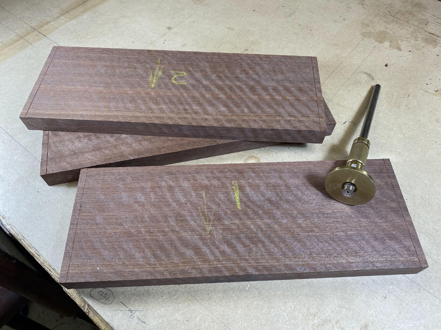
This is the last part of the build - completing of the drawer bottoms and pulls.
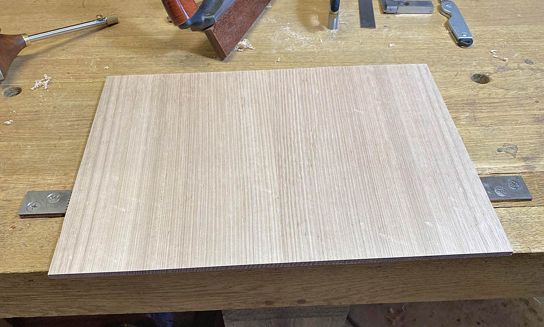
A panel was prepared some weeks ago. 1/4" thick Tasmanian Oak. This was made up of two, book matched boards. Blue tape was used to pull the jointed edges together. Clamps are unnecessary for this task ...
Measure off the full width of the drawer bottom from inside the slips ...
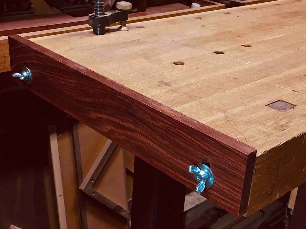
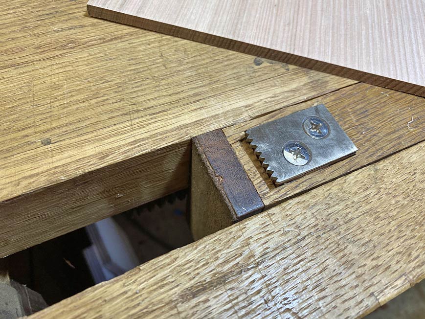
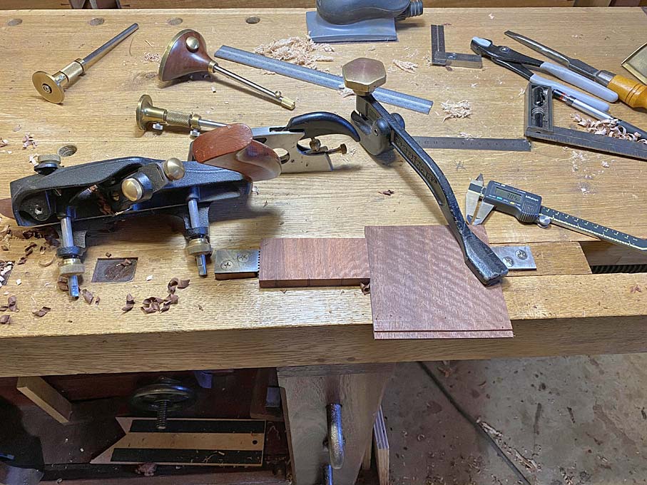
Of possible interest is the work holding for the drawer bottom ...
The bench dogs on each side were made from sections of unhardened O1 steel, and filed into teeth.
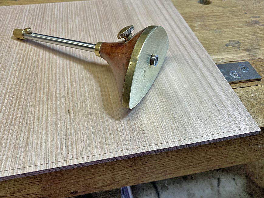
Another heads-up is the arm for this cutting guard. Some while back, Veritas brought out a gauge with a fine adjuster. They now sell the arms to upgrade existing gauges, which is what I have done here to a wheel gauge I made ...
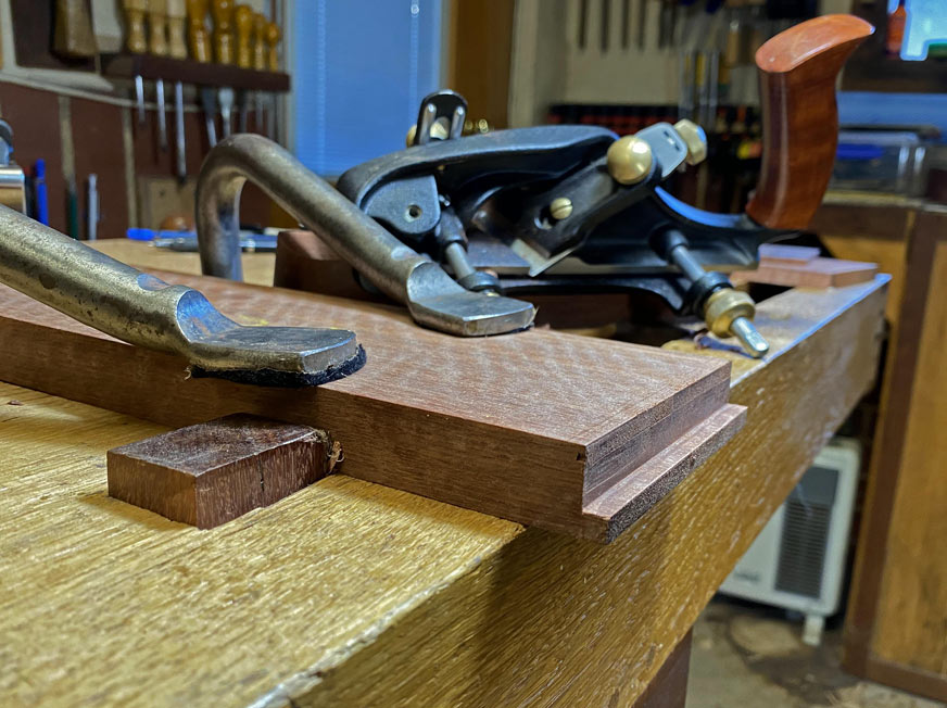
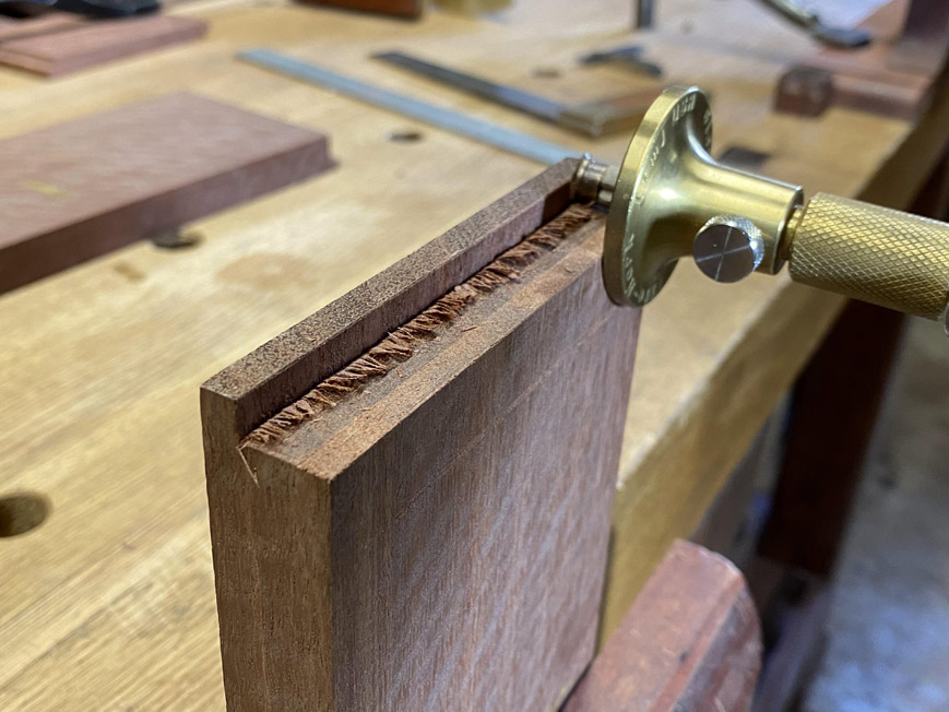
Here the tongue is marked (about 4mm). This will fit into the groove in the slip.
The thickness of the tongue is marked (3mm).
The tongue is planed ...
The fit is tested with a spare slip ...
The bottom was about 1mm too wide to fit. A LN edge was perfect to re-joint one side ...
Re-establish the tongue with a shoulder plane ...
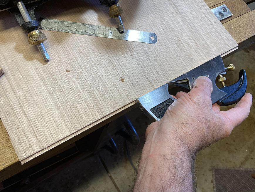
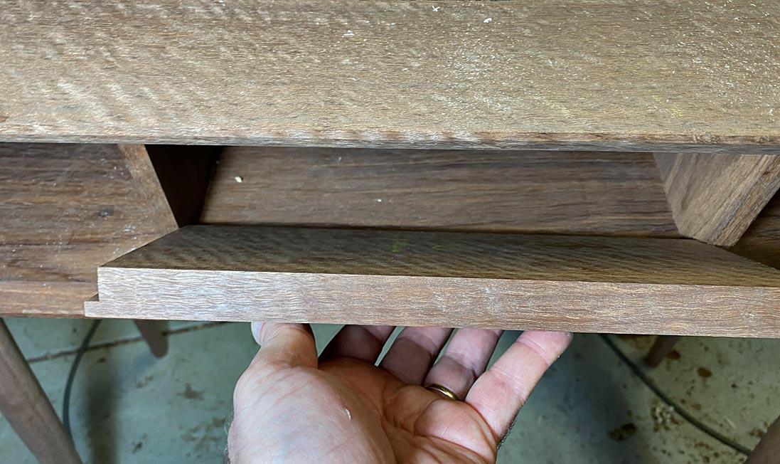
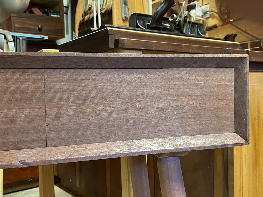
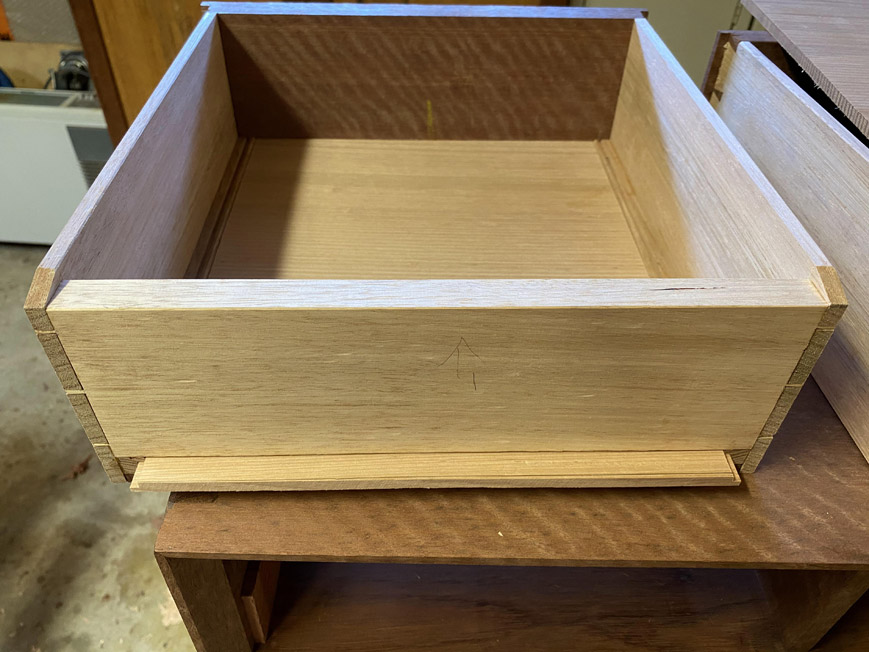
Slide the bottom in. At this time it is just a dry fit. The front, which remains 1/4" thick to fit to 1/4" groove at the rear of the drawer front, is not yet pushed home. The front groove will hold the one end firmly, allowing movement towards the rear of the drawer.
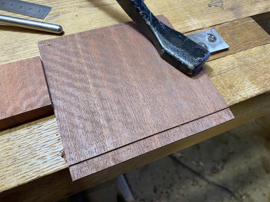
The drawers require pulls. The aim is to make the pulls "vanish" as much as possible. To do this, the shape is kept simple, and the wood is a section from the drawer fronts. Here it is being planed to 1/4" thickness.

Set up to make the pulls ...
A 10mm wide rebate is planed on both sides. This will be completed on the reverse side as well, to create a tenon 3mm thick.
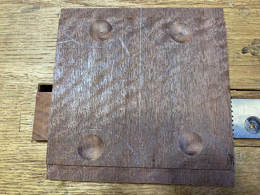
Four sections are marked off for the pulls (only three are needed) ..
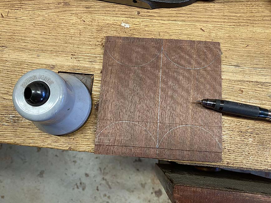
A router is used to create dimples for a finger grip on the underside of the pull (three were needed and were good here; one could be tossed) ...
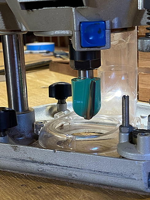
The outlines are cut out ...
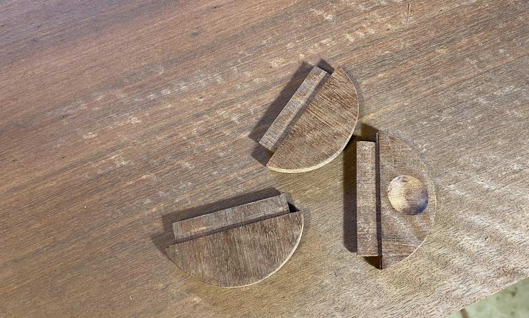
The router is again used, this time to create a 3mm x 50mm mortice in the drawer fronts for the pulls ...
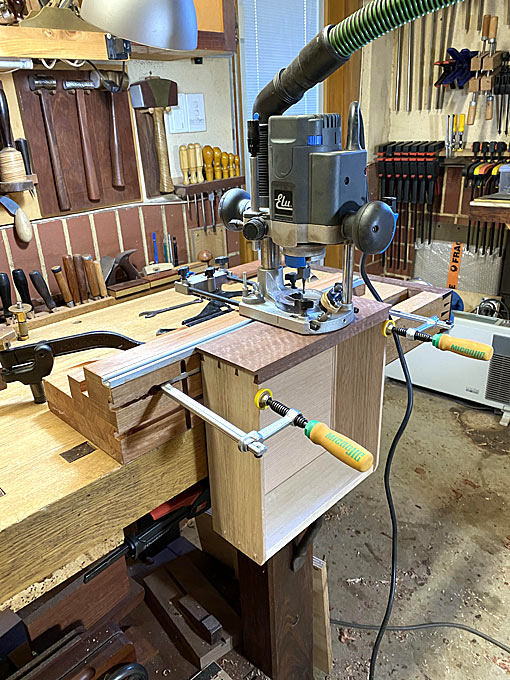
The final section of the build is the drawer back. I decided to use Jarrah to match the rest - one never knows whether the hall table will become a room divider.
The newly-purchased JessEm Clear-Cut TS Stock Guides make a clean, accurate rip that much easier ...
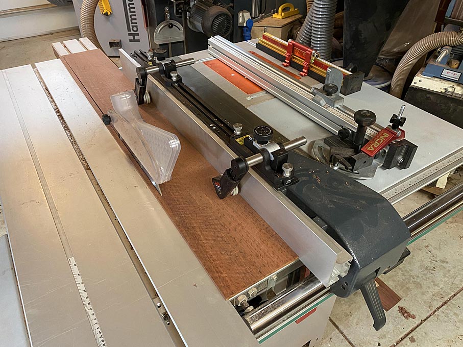
The next post will show the completed hall table.
Regards from Perth
DerekVisit www.inthewoodshop.com for tutorials on constructing handtools, handtool reviews, and my trials and tribulations with furniture builds.

 Reply With Quote


Similar Threads
-
Entry Hall Mirror - WIP
By Rookie in forum WOODWORK - GENERALReplies: 5Last Post: 31st August 2010, 11:12 PM -
A gift for my Niece's 21st ... ssshhh don't tell her!
By Touchwood in forum BANDSAWN BOXESReplies: 10Last Post: 22nd November 2009, 11:13 AM -
hall table, wine table, water stone box
By driftit in forum WOODWORK - GENERALReplies: 6Last Post: 1st May 2009, 11:20 PM -
Project 1 - Entry Way Table
By `Felix` in forum WOODWORK PICSReplies: 13Last Post: 25th March 2004, 03:54 PM
