

 Thanks:
  Likes:
  Needs Pictures: 0
 Picture(s) thanks:
Results 76 to 90 of 187
Thread: Lingerie Chest
-
14th July 2015, 08:58 PM #76
 SENIOR MEMBER


- Join Date
- Jan 2001
- Location
- Langwarrin, Victoria, Australia
- Age
- 56
- Posts
- 677

Been reading and re-reading this for the last day or two trying to contemplate the issue.
I am by no means as skilled as you lot ... So pardon my ignorance if you can ..
So the blades (thanks ... Hadn't heard this term before) and runners are dove tailed into the stiles, which are already marked out.
So tell me why this can't be done with the carcass disassembled ? And then reassembled once all elements are complete ?
Now, I realise that the sides are curved, and this poses some challenges.
But if the only issue is cricking your neck to see the inside of the stiles to mark out ... Pull it apart.
Sorry if I have missed the obvious.Glenn Visca
-
14th July 2015 08:58 PM # ADSGoogle Adsense Advertisement
- Join Date
- Always
- Location
- Advertising world
- Age
- 2010
- Posts
- Many
-
14th July 2015, 09:18 PM #77
Be inspired. Be creative. Be bold.
- Join Date
- Apr 2001
- Location
- Perth
- Posts
- 10,872
Hi Glenn
With a parallel sided carcase, all one needs is a story stick to mark off the dados for the drawer runners. You can rout them, or what ever, sides separately - no problem as the grooves are vertical/square on both sides. As long as they are done accurately, the dados will face each other, that is, will be coplanar.
But what happens when you have a curved side that no longer has the ease of routing a dado this way. If you rout straight down into the side, it will be at the same angle as the curve. There are multiple curves, one for each drawer runner.
Working from the outside is straightforward, especially with the carcase together as the blades just need to be horizontal. This will be the case at the rear of the carcase.
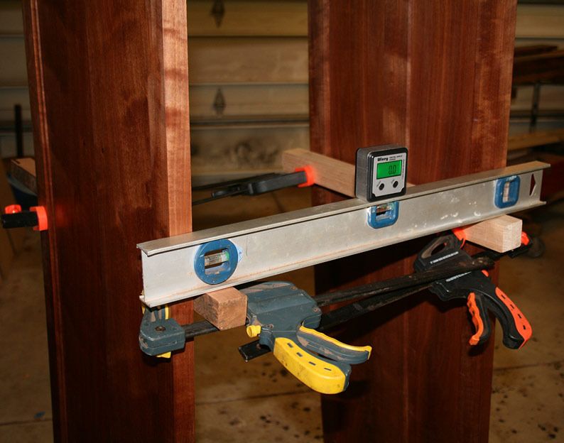
Keeping the drawer blades coplanar is the issue when you are working from the inside of the carcase ...
Here is as much as the sides are out-of-square at this position ...
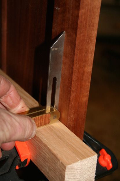
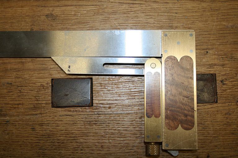
Marking and working is easier when the complementary angles remain as a reference.
Consequently, I need a guide for each housing to achieve coplanar, and then this can be used as a reference to mark the dovetails (as done for the base rails into the legs.
Regards from Perth
DerekVisit www.inthewoodshop.com for tutorials on constructing handtools, handtool reviews, and my trials and tribulations with furniture builds.
-
14th July 2015, 09:56 PM #78
SENIOR MEMBER
- Join Date
- Jan 2001
- Location
- Langwarrin, Victoria, Australia
- Age
- 56
- Posts
- 677
Yes ... I see the curved sides present all sorts of what my employer used to call "opportunities".
You are a better man than I ...
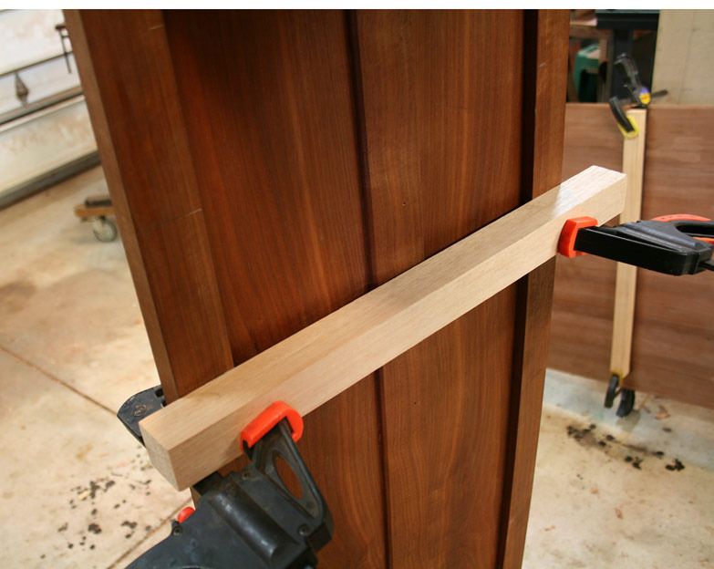
So aren't individual guides the answer then ? As shown in your picture, you can clamp a rail across the front to determine horizontal. Use that rail and stile to determine intersecting angles.
Cut template to matching angles that fits inside the carcass and clamp into position. Maybe ... Just maybe ... Cut a negative template that spans side to side, tack in place on the inside of the Stiles, then carefully cut the template in half leaving each side attached. Disassemble carcass and now you have space to work.
If keeping the carcass together is a must, I have another pissy idea using some technology ... But you will laugh at me ... So keeping it to myself at the moment.Glenn Visca
-
14th July 2015, 10:52 PM #79
GOLD MEMBER
- Join Date
- Oct 2014
- Location
- Caroline Springs, VIC
- Posts
- 1,645
instead of just a sliding dovetail, you could use (if space allows) a housed sliding dovetail. instead of having to mess around with the angle from the stile curves creating different blade rails, you simply create the dados to be plum/90degrees to the blade rails in the stiles. then just chop out, rout out the dovetail socket. the dovetail tails on the rails are plain jane, the only difference between each blade rail is the shoulder length.
slide_dt.jpg
-
14th July 2015, 11:08 PM #80
Be inspired. Be creative. Be bold.
- Join Date
- Apr 2001
- Location
- Perth
- Posts
- 10,872
Hi Kuffy
Thank you for the illustration. That is what is planned, as I mentioned above ..
I need a guide for each housing to achieve coplanar, and then this can be used as a reference to mark the dovetails ...
The main difference will be that the housing will be from the inside, very shallow (since there is not much depth to work with), and stopped (a curved face will be added afterwards).
Regards from Perth
DerekVisit www.inthewoodshop.com for tutorials on constructing handtools, handtool reviews, and my trials and tribulations with furniture builds.
-
14th July 2015, 11:57 PM #81
GOLD MEMBER
- Join Date
- Feb 2003
- Location
- back in Alberta for a while
- Age
- 68
- Posts
- 12,006
Hi Derek
suitably abashed
here is the sketch I mentioned last night.
Drawer Carcass.jpg
It might be for a table, but the drawer support and guiding construction -- half lap dovetails matched with tenons the other end -- applies equally to chests
your drawers
1) I have the impression that your lingerie chest is relatively narrow -- around 400-450mm wide.
please forgive me if I am wrong, but if it is that narrow, and you don't intend installing dust boards between each drawer, you could mount the alternate drawers on runners attached to the styles.
2) installing the web frames or drawer blades
I must be missing something. If you cut stopped dovetail dados -- which could be dovetailed on either the bottom or top only -- these dados could be cut normal (i.e. 90° to the tangent where they meet the style). To compensate the for the angle, you would cut angled dovetailed shaped tenons on the end of each rail. The construction would be similar to an angled rail to leg chair joint.
3) the Blum Tip-on closers.
These worry me as from the Blum site they appear to be intended for use with low friction mechanical drawer runners. I'm fearful your drawers will be too heavy leading to destructive horizontal forces on the carcass.
4) the drawers themselves.
my preference would be to adopt 12-14mm drawer sides and support the drawer base using slips.Last edited by ian; 15th July 2015 at 12:00 AM. Reason: substituted fearful for afraid
regards from Alberta, Canada
ian
-
15th July 2015, 09:35 AM #82
GOLD MEMBER
- Join Date
- May 2007
- Location
- Sth Gippsland Vic
- Posts
- 4,470
Im sure You Know Derek, you mentioned it before, and as Ian said before here somewhere as well, the Key to building the right way is with our second most important tool after our Brain , that is the pencil and paper.
So many Hobby guys don't do it or realize how much they will learn by trying it.
Working it all out to scale on paper is the only way forward if people want to get above the average struggle of building with out planning.
Design understanding and efficiency of build rapidly increase within a few attempts . mistakes drop away . a cutting list can be produced and all components are cut at once if you want .
Problem solving is easy and visible .
Its traditional , and goes with hand tool construction .
There is no way the pieces of the past could have been made without it .
Its a big help with understanding proportion and correcting it on other designs later as well.
Rob
-
15th July 2015, 09:56 AM #83
SENIOR MEMBER
- Join Date
- Jan 2008
- Location
- NSW southern Highlands
- Posts
- 548
A scale model is also of great benefit, and IMHO better, and more enjoyable than drawings.

Regards
-
15th July 2015, 01:11 PM #84
Be inspired. Be creative. Be bold.
- Join Date
- Apr 2001
- Location
- Perth
- Posts
- 10,872
Hi Ianyour drawers
1) I have the impression that your lingerie chest is relatively narrow -- around 400-450mm wide.
please forgive me if I am wrong, but if it is that narrow, and you don't intend installing dust boards between each drawer, you could mount the alternate drawers on runners attached to the styles.
Thanks for the time to research the construction drawing. It makes a good general reference planner, but may be confusing for a novice as the various parts change and do not match. But the idea is there and is helpful. Construction in this chest is along those traditional lines.
The chest is (internally) 440mm at the top and 560mm at the bottom. I did not plan on dust boards as they will over-complicate matters in regard to fitting parts. The upper drawer - used for jewellery - will have a dust board, simply because there is a secret drawer above (as planned in at this stage).
I do not want hanging runners for two reasons: firstly, while the design may be modern, the construction is traditional. So no metal runners. Wooden runners would add too much friction to the drawers (see Tip On, below).
2) installing the web frames or drawer blades
I must be missing something. If you cut stopped dovetail dados -- which could be dovetailed on either the bottom or top only -- these dados could be cut normal (i.e. 90° to the tangent where they meet the style). To compensate the for the angle, you would cut angled dovetailed shaped tenons on the end of each rail. The construction would be similar to an angled rail to leg chair joint.
I plan to cut the housings first. They will be very shallow - just enough flat area to register on from the inside - where there is enough clearance between the leg and the reinforcing to the panel to work, and long enough to fit the end of the blade (a curved face will be added afterwards). The length of the front blade will be sized such that the base of the dovetails register on the flats. Then they can be marked out and cut.
The leg thickness above the panel (for dovetailing) is 10mm (about 3/8"). I estimate that the housing will remove about 1-2mm, and the dovetail will then need to be about 5mm (about 3/16") deep. The angled side faces down, the straight side faces up.
The legs are 45mm wide. I plan to add on a 25mm wide filet behind the leg to extend this width. The curved drawer face will be 22mm (about 7/8"), sitting inward of the outside edge by 1mm, and will butt against a stop (2mm needed for the Tip On), which leaves a 45mm long sliding dovetail at the front. The front and rear drawer blades will be 50mm (2") wide.
The drawer is similar to this ...

You are correct. I was concerned about the same thing, but have tested them out and they have a strong spring. At any rate, all they need to do is push out the drawer about an inch - enough to grip the drawer using the underside as a pull. The worst case scenario is that I add drawer pulls - but I do like the idea of a simple, flat face to the chest.3) the Blum Tip-on closers.
These worry me as from the Blum site they appear to be intended for use with low friction mechanical drawer runners. I'm fearful your drawers will be too heavy leading to destructive horizontal forces on the carcass.
That is how I build drawers. We are on the same page. The only variation is that the drawer sides will be shaped to the contour of the chest sides. That is less complicated than it sounds since the curve is quite subtle until it gets lower - not too much waste to remove.4) the drawers themselves.
my preference would be to adopt 12-14mm drawer sides and support the drawer base using slips.
Regards from Perth
DerekVisit www.inthewoodshop.com for tutorials on constructing handtools, handtool reviews, and my trials and tribulations with furniture builds.
-
15th July 2015, 01:27 PM #85
Be inspired. Be creative. Be bold.
- Join Date
- Apr 2001
- Location
- Perth
- Posts
- 10,872
Rob, you have my agreement. However I am guilty of not following this as much as I would really like to do. Originally Posted by auscab

All of my builds are worked out beforehand with sketches. But not detailed drawings. I do not draw in CAD - I really need to take time to learn Sketch Up.
The reason for not having final details is that the pieces I now tend to build are difficult to draw in 3-D (look at what happened when I built Wegner's "The Chair"). They have curves and compound angles. Consequently they are calculated as needed - but I do tend to think several steps ahead, and nothing gets built or glued until it is certain. My questions here hopefully do not suggest chaos - they are just an attempt to share the process of problem solving between us. After all, that is how we learn, and is the fun bit. Yes?
Without a doubt you are correct if building for production.
Regards from Perth
DerekVisit www.inthewoodshop.com for tutorials on constructing handtools, handtool reviews, and my trials and tribulations with furniture builds.
-
15th July 2015, 02:45 PM #86
GOLD MEMBER
- Join Date
- May 2007
- Location
- Sth Gippsland Vic
- Posts
- 4,470
Yeah , I understand it's not chaos, and Its providing good discussion . Originally Posted by derekcohen
I wouldn't go trying to draw it on a computer , paper and pencil is the way to go . The only problem is storing your creations so you can find them later. That means another set of drawers .
I use one of these drawing boards ,It can be done the same on just a flat board though.
Drawer storage on the left , a Red Cedar creation .
Library of woodwork behind me and a mess in between on the desk.
mostly , but not all the time, Curves are not a problem , its the accurate distances in between and the angles that need to be correct , the correct curve gets worked out on the bench or with the template .
Rob
-
15th July 2015, 04:36 PM #87
Be inspired. Be creative. Be bold.
- Join Date
- Apr 2001
- Location
- Perth
- Posts
- 10,872
That's where we will differ.Curves are not a problem , its the accurate distances in between and the angles that need to be correct , the correct curve gets worked out on the bench or with the template
I plot everything by drawing full size on 3mm MDF - all the details. I make my templates from these drawings, tracing the drawings to MDF masters. I can measure from this ...

Details, such as compound angles, are similarly drawn and templates are created ..

This ..

... became this ...

Just for interest, before I studied to become a shrink, I completed most of a degree as a quantity surveyor. All of this was in building construction and drafting - in those days at a drawing boards. Both my late father and my sister are architects, so I am steeped in drafting. I start with rough sketches, and then may create more detailed drawings by drafting on MDF.
Attempting to draw up the Wegner chair from supplied dimensions made me aware of the impossibility of creating a 2-D drawing of the compound curves in this chair, that is, from something that needs to be drawing on CAD and seen in 3-D ..

For all this, when the joinery is drawn and clear, sh-t still happens - the hand does not follow exactly where the eye wants it to go, and running repairs result in "corrections". These may be slight, but they change all that follows, and it becomes necessary to adjust.
Also, my preference is to work out a design first and not worry about how it will be built. Or if it can be built with my existing knowledge. If I only built what I knew to do, then my designs would be boringly basic and mundane (well .. more than they are already!). For this reason it becomes a part of the process to work out some of the joinery details later .. sometimes quite late into the piece. And this is OK just as long as one thinks far enough ahead to give oneself options.
I am interested to hear how others go about this process.
Regards from Perth
DerekVisit www.inthewoodshop.com for tutorials on constructing handtools, handtool reviews, and my trials and tribulations with furniture builds.
-
15th July 2015, 04:59 PM #88
GOLD MEMBER
- Join Date
- May 2007
- Location
- Sth Gippsland Vic
- Posts
- 4,470
No difference ,I do the same when I need to .
These chairs are sitting on the full size plan which templates were taken from.
I would usually still do the scale drawing first, the client OK's that , then I do the big one , the big ones can take some time !!
I remember spending 8 hours on some .
I generally do all chairs and sofas this way . Not many cabinets . Mainly because most are not curved I suppose . I did a table last week with curves and that was a full size plan drawn on it's top , for its base . it was scraped off later so we could start polishing it .
Rob
-
15th July 2015, 06:26 PM #89
GOLD MEMBER
- Join Date
- Oct 2014
- Location
- Caroline Springs, VIC
- Posts
- 1,645
I draw everything in sketchup. I pull the dimensions from the drawing as I need them. or for complex wiggly curves, i just print out a 1:1 copy of the component (often needing to span many A4 pages stickytaped together) and use this as a tracing template. if its just a standard curve such as in this lingerie chest, I would just look up what the offset is between a 3 point arc and mark it out using a bendy stick.
sketchup, is fantastic. the first hour or two was a real pain because it operates much differently to AutoCAD in which i was accustomed. once I got used to it, its a breeze to draw up basic pieces such as...shaker bedside tables. it pretty easy to draw up complex curves too, but you just gotta think a lil harder about what your doing. I would recommend sketchup over any other drawing program for creating plans. I still prefer AutoCAD for creating files for CNC routing.
I worked in places where full size samples were kept and measurements taken from these. it was a nightmare since I was on the CNC and the machine doesnt know the component is slightly different from last time. one guy uses his ruler and measures 41mm, the next guy use calipers and measures 42.2mm, and the next guys "knows" it is supposed to be 45mm...shambles!!!!
-
16th July 2015, 04:21 AM #90
Be inspired. Be creative. Be bold.
- Join Date
- Apr 2001
- Location
- Perth
- Posts
- 10,872
A simple solution for cutting the dovetails occurred to me.
I have planned to add a filet strip behind the front leg to lengthen the sliding dovetail for the front drawer blade. What I shall do is clamp one on each side and inside the rear leg, and then mark and saw the dovetails from the rear (the rear was always going to be marked and sawn from outside).
Here is the side again (the rear rebates have yet to be cut):
The rebate will be 6mm deep, which is also the depth of the dovetail. Once the dovetail is sawn and the waste removed, the clamped filet can be moved and glued behind the front, as planned. This will ensure that both front and back are coplanar.
Both sides are done at the same time.
The drawer blade is made to fit beforehand, and dovetailed. This is made doublt width (100mm wide), and then ripped into two pieces - one for the rear and the other for the front.
So, in effect, the front sliding dovetails are fitted from the outside of the rear of the carcase.
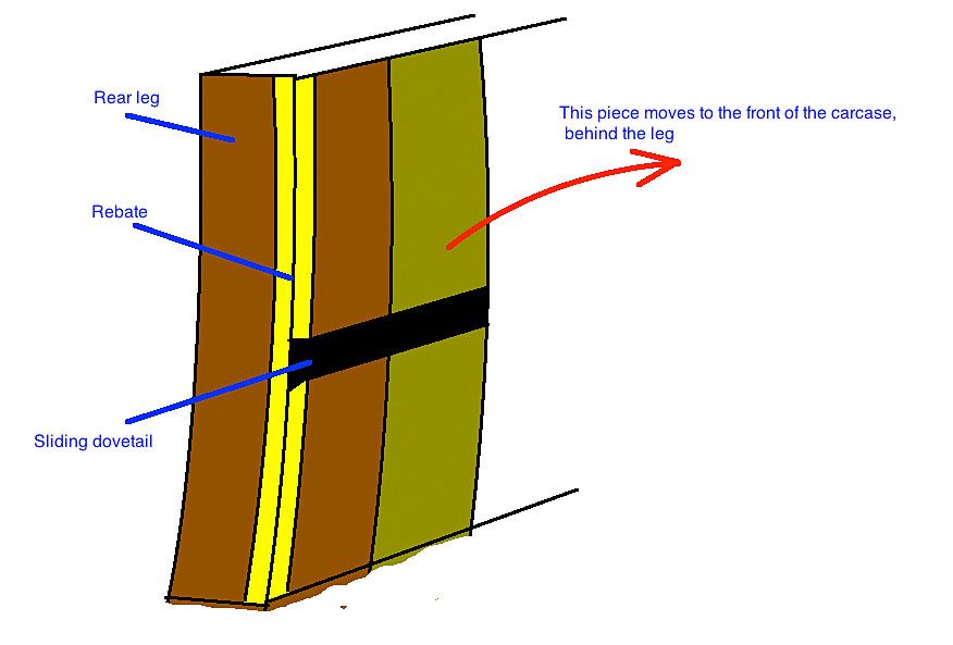
What do you think?
Regards from Perth
DerekVisit www.inthewoodshop.com for tutorials on constructing handtools, handtool reviews, and my trials and tribulations with furniture builds.


 Reply With Quote


Similar Threads
-
Lingerie Chest
By derekcohen in forum FURNITURE, JOINERY, CABINETMAKING - formerly BIG STUFFReplies: 17Last Post: 30th November 2014, 05:29 PM -
Sea Chest
By LR09WA in forum WOODWORK - GENERALReplies: 14Last Post: 11th June 2011, 08:00 PM -
Ice Chest
By rod1949 in forum Links to: TIMBER & HARDWARE SUPPPLIERSReplies: 1Last Post: 15th September 2004, 08:13 PM -
Chest
By GRS in forum WOODWORK PICSReplies: 8Last Post: 7th July 2004, 12:26 PM
