

 Thanks:
  Likes:
  Needs Pictures: 0
 Picture(s) thanks: 0
Results 61 to 75 of 89
Thread: Lathe Help
-
24th March 2014, 12:09 PM #61
 Senior Member


- Join Date
- Mar 2009
- Location
- Melbourne
- Age
- 54
- Posts
- 380

G'day neevo,
You might also want to check the adjustment of the gibs on both the top and cross slides if you have not already done so.
Tightening the gib increases the amount of force required to move the slide and while this doesn�t remove any backlash as such it makes it harder for the cutting force pull the slide into the backlash. This is not an ideal fix as it also increases the force required to move the slides which makes the feed handle stiff to turn and will also wear the slides quicker although this is unlikely to be a real concern unless you use the lathe a lot.
A possible workaround is to replace one of the gib adjusting screws on your cross and top slides with a cap screw so it can be tightened or loosened easily as required.
Cross slide backlash is a real worry when parting off so if you can easily tighten up your cross slide when parting or working to tight tolerances and let it run looser for normal operations this might be all you need to get by.
Cheers,
Greg.
-
24th March 2014 12:09 PM # ADSGoogle Adsense Advertisement
- Join Date
- Always
- Location
- Advertising world
- Age
- 2010
- Posts
- Many
-
25th March 2014, 01:24 PM #62
Senior Member
- Join Date
- Sep 2009
- Location
- Penrith, NSW
- Posts
- 116
Thanks to a forum member off this site I received a load of the missing gears today at work. Not all of them have been acquired yet but I have enough to be able to connect up the lead screw and have a play with that tonight.
Still plenty of gears to get, so if anyone has any they want to get rid of let me know.
Still looking for: 16, 24, 36, 40, 56 and 54/18
Then I will be on the hunt for the metric gears too.
-
25th March 2014, 02:55 PM #63
GOLD MEMBER
- Join Date
- Jun 2007
- Location
- sydney
- Age
- 64
- Posts
- 3,566
Can do the gears listed for $173.00,and also the metric for additional if required.
-
25th March 2014, 07:46 PM #64
Senior Member
- Join Date
- Sep 2009
- Location
- Penrith, NSW
- Posts
- 116
Thanks pipeclay, I will probably take you up on that offer, just need to build the toy fund back up a little as it's taken a hammering recently and so I'm a little in the red

I managed to get the power feed working this evening. Works a treat however I have another issue (of course I do). It seems like the lever to engage the half nuts is very loose and when in power feed can drop down on its own, disengaging the feed.
Looked online but cannot find the answer. Anyone know what's going on?
-
26th March 2014, 02:24 AM #65
GOLD MEMBER
- Join Date
- Jun 2007
- Location
- sydney
- Age
- 64
- Posts
- 3,566
Are the 2 hex nuts coming through the apron at the rear of the half nut lever tight.
If they are then there may be wear in the half nuts.
-
26th March 2014, 07:42 AM #66
Senior Member
- Join Date
- Sep 2009
- Location
- Penrith, NSW
- Posts
- 116
Do I have to engage the half nuts and then snug them up or does it not matter?
I highly suspect the half nuts are probably worn, everything else on this lathe is and give its age that's not a huge surprise.
-
26th March 2014, 01:51 PM #67
GOLD MEMBER
- Join Date
- Jun 2007
- Location
- sydney
- Age
- 64
- Posts
- 3,566
After having a look at one at AMWH it could also more likely be the adjustment for the rotational tension on the half nut handle body.
To locate the adjustment point you would need to remove the front 2 screws attaching the carriage to the saddle,and then slide the saddle along the lead screw or remove it totally from the machine.
Once the saddle is clear enough of the carriage a hole should be seen in the centre of where the body of the half nut handle passes through.
In this hole should be a grub screw,spring and a pin with a vee on one end,this vee applies pressure to a similar vee cut into the od of the half nut handle.
This grub screw may be loose,the spring may be missing or broken or the vee pin may be missing.
If you first try turning the grub screw to apply more load to the spring and vee pin this should hold the half nut handle in position.
If this dosent work then removal of the grub screw and associated parts will need to be done so as to ascertain the problem.
-
26th March 2014, 01:52 PM #68
Senior Member
- Join Date
- Sep 2009
- Location
- Penrith, NSW
- Posts
- 116
Awesome! Thanks.
-
28th March 2014, 09:55 PM #69
Blacksmith, Cabinetmaker, Machinist, Messmaker
- Join Date
- Dec 2011
- Location
- Canberra
- Age
- 40
- Posts
- 4,467
Hi Ed,
Could you supply a link to the belt you got? My mars lathe has a composite belt but I could do with something endless and a bit thinner. On that how thick is that belt?
Cheers,
Ew1915 17"x50" LeBlond heavy duty Lathe, 24" Queen city shaper, 1970's G Vernier FV.3.TO Universal Mill, 1958 Blohm HFS 6 surface grinder, 1942 Rivett 715 Lathe, 14"x40" Antrac Lathe, Startrite H225 Bandsaw, 1949 Hercus Camelback Drill press, 1947 Holbrook C10 Lathe.
-
29th March 2014, 07:57 AM #70
Senior Member
- Join Date
- Sep 2009
- Location
- Penrith, NSW
- Posts
- 116
I looked here for a part number after measuring the pulley to pulley distance:
http://www.goodyearep.com/ProductsDetail.aspx?id=3128
Mine was 46" so I opted for the 6PK1170 as 6 ribs was just less than 1" wide. I popped this into eBay and came up with one from China for $12 AUD (although the listing incorrectly had it as 90" but the mm measurement was correct).
http://bit.ly/1i1ZwAx
Works a treat.
-
18th April 2014, 04:19 PM #71
Senior Member
- Join Date
- Sep 2009
- Location
- Penrith, NSW
- Posts
- 116
Lathe Help
I've been collecting stuff for a future VFD mod and wanted to also add an RPM sensor to the lathe too. Bought some cheapies off eBay so that I could test the concept and replace as they failed or didn't work.
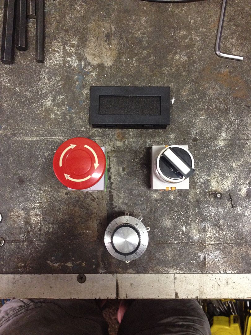
I have a plastic junction box on its way to mount it all in (thinking I will mount it above the headstock so I can access it with the left hand) and will be putting the following into it (RPM display, mushroom kill switch, 2 pole on/off switch, pot for speed adjust):
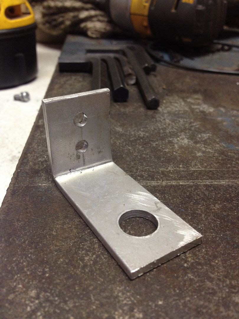
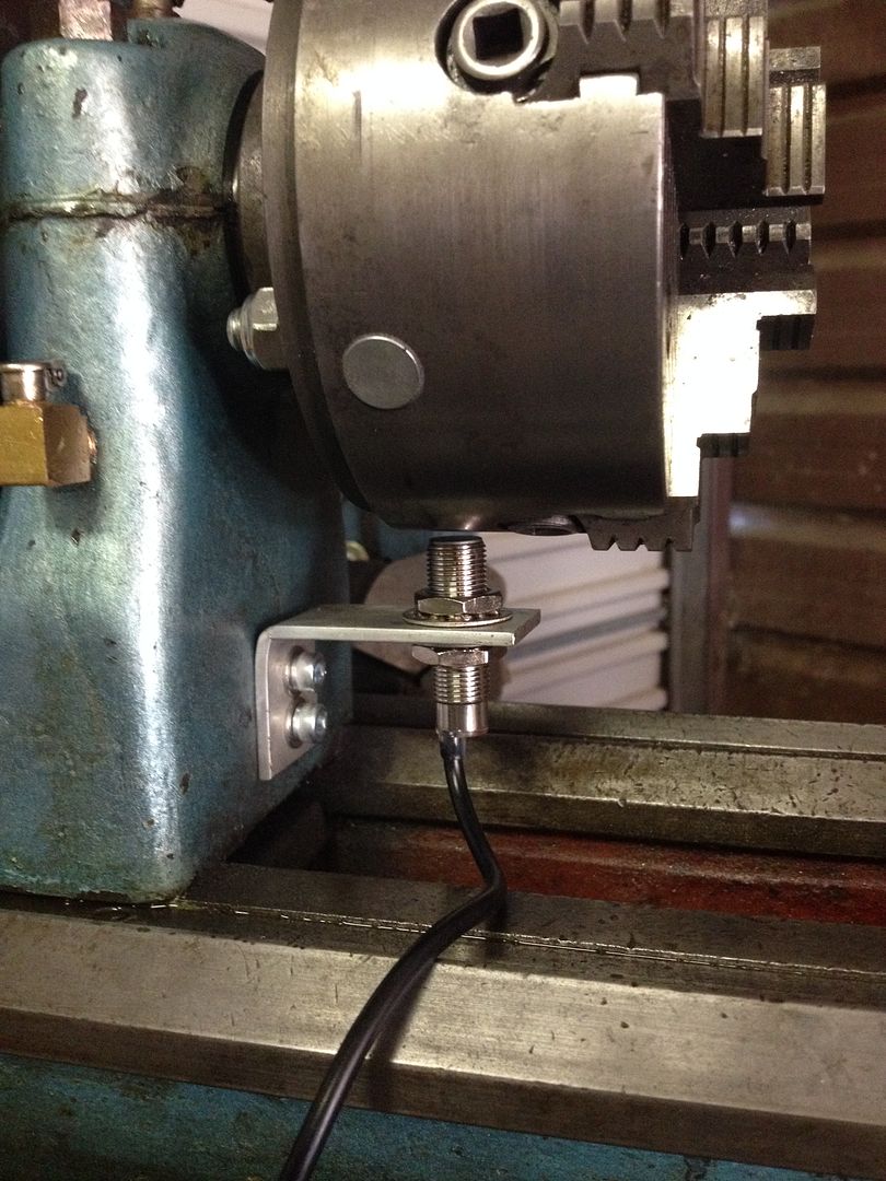
Today I decided to mount the speed sensor. I pulled some 3mm Alu stock out and made up a little right angled bracket:
I decided to mount the bracket under the chuck as it would be out of the way. Tapping into the headstock was tough as access was limited, but all went well:
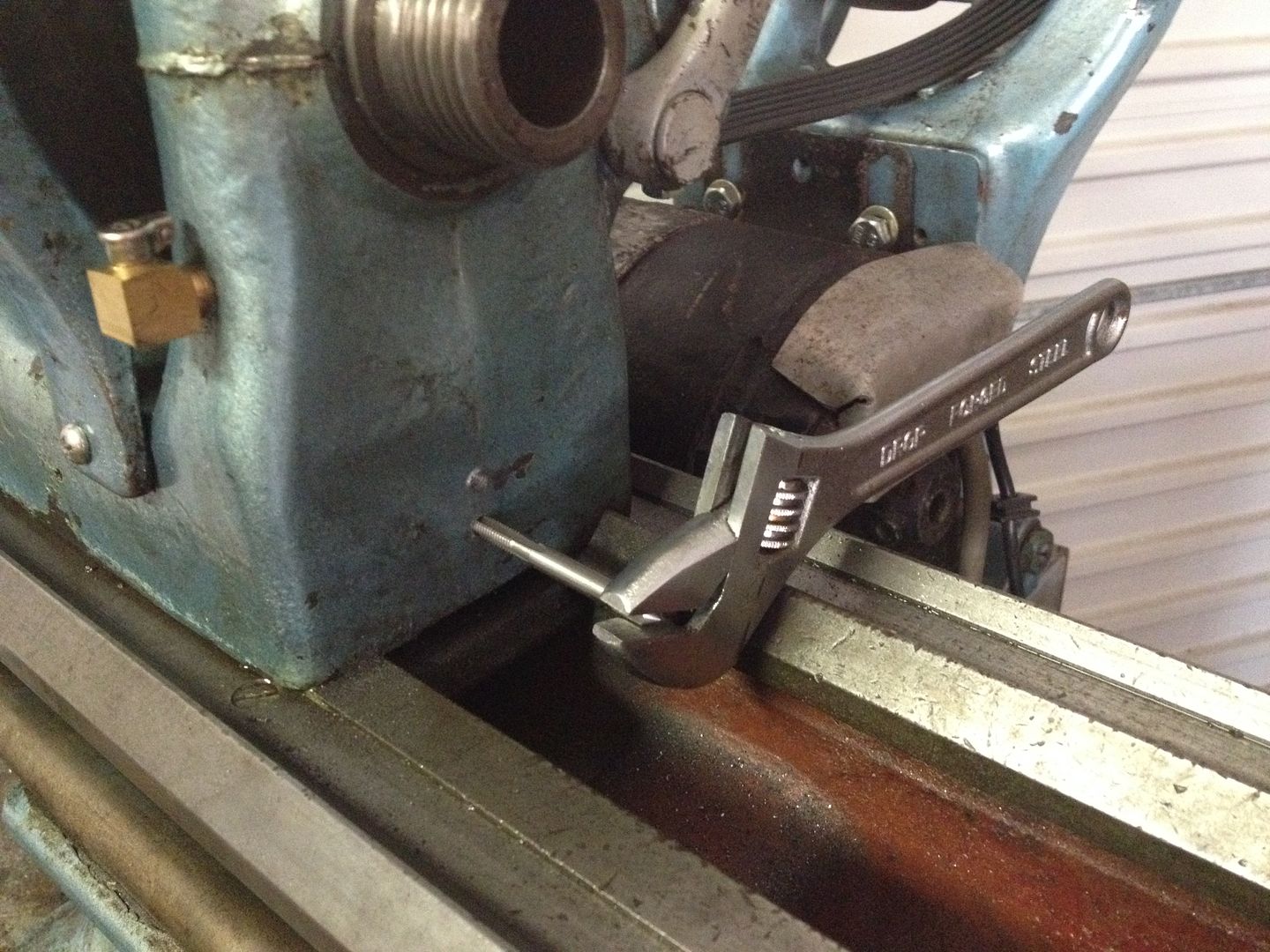
Test fit:
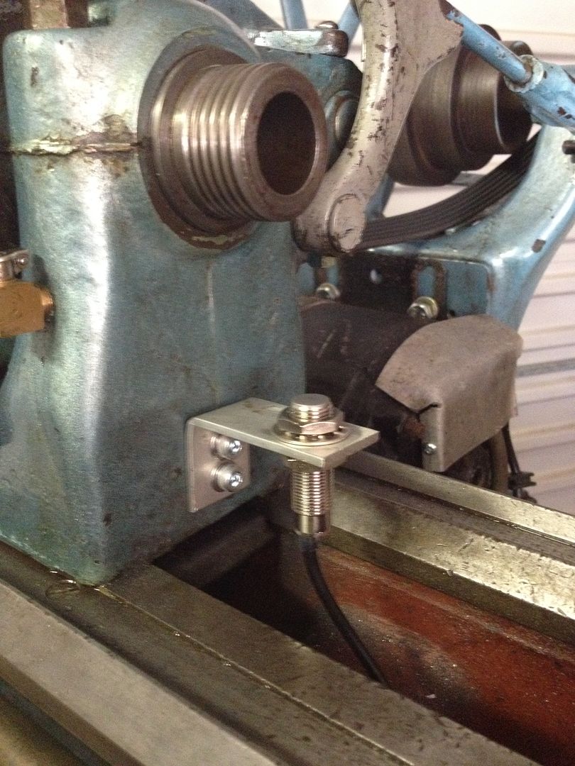
Next up was to mount the magnet. Not sure if this is seriously wrong but I thought the best place would be the chuck, so I marked it with a sharpie:
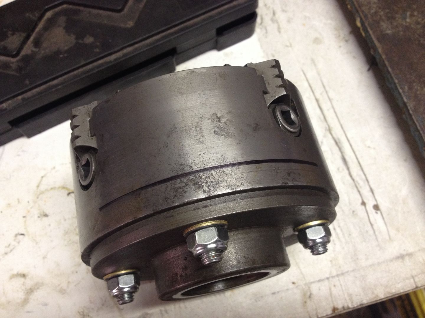
Drilled and mounted nice and flush:
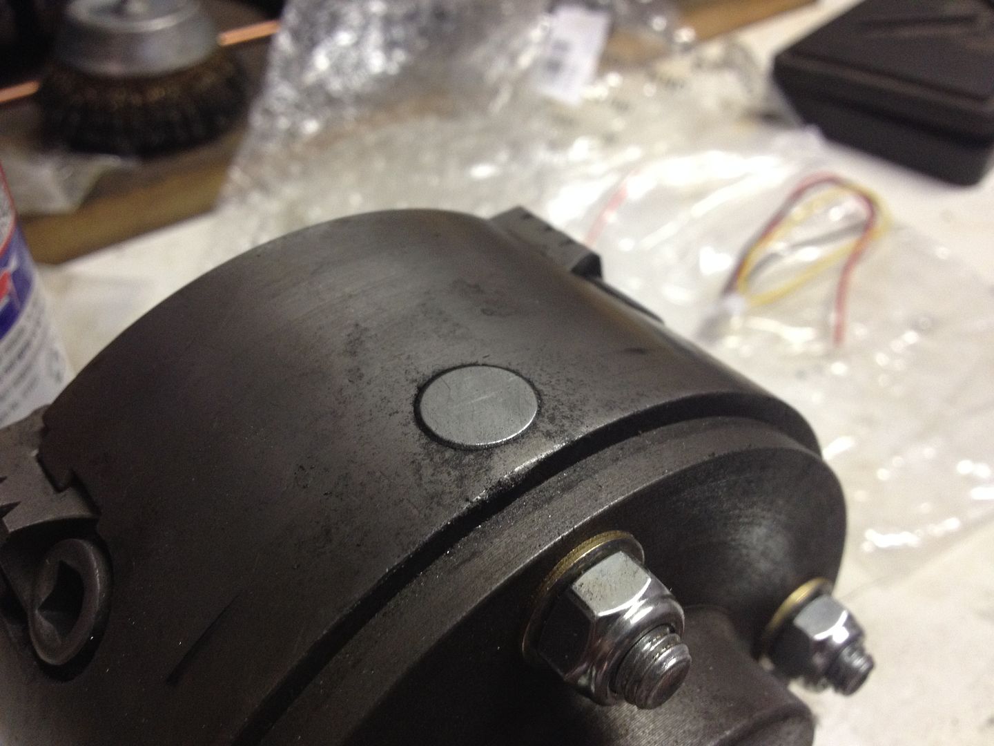
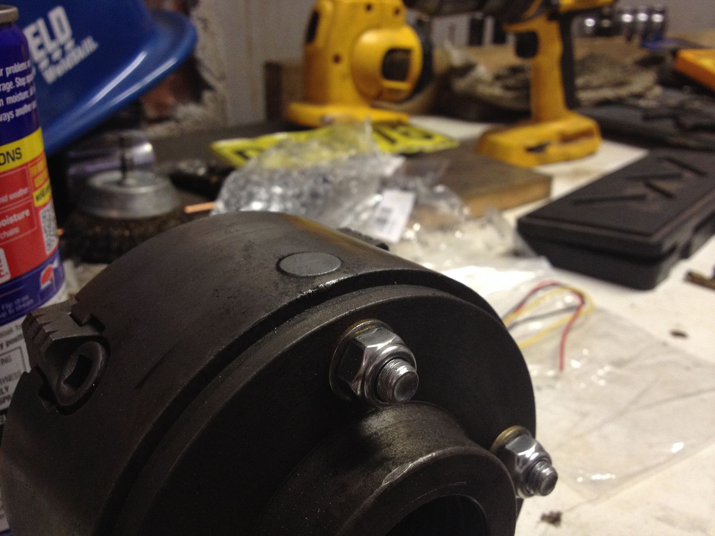
I epoxied it in place which is silly as I have a hot glue gun which would have been perfect and almost immediate.
All done and ready for wiring:
Next job will be to finish the wiring into the junction box, plus I am thinking of scrapping the current lathe stand and making something much more heavy duty/sturdy out of 40mm square steel tube.
-
19th April 2014, 02:24 AM #72
GOLD MEMBER
- Join Date
- Jun 2007
- Location
- sydney
- Age
- 64
- Posts
- 3,566
Have you taken into consideration if you change chucks or use a collet chuck.
Have you also taken into account swarf building up on the magnet or fine wire pieces of swarf rapping around the chuck.
-
19th April 2014, 09:40 AM #73
Senior Member
- Join Date
- Sep 2009
- Location
- Penrith, NSW
- Posts
- 116
Lathe Help
First & second one I did pipeclay, as I mounted it sufficiently far out the it would fit a 6" chuck too. Plus magnets are easy to come by so I was going to fit another magnet to a 3 jaw in time.
Third one I also did as I epoxied it in with no gaps around the magnet so I can use the compressor to blow bits off it.
Last one (swarf wrapping around the chuck) I did not
I looked everywhere on the net for where to mount the pickup, but couldn't find anything. Do you have any suggestions on where to mount it? Need it to pickup spindle speed which limits the options a bit as space is pretty limited.
-
19th April 2014, 10:58 AM #74
Blacksmith, Cabinetmaker, Machinist, Messmaker
- Join Date
- Dec 2011
- Location
- Canberra
- Age
- 40
- Posts
- 4,467
Hi,
I mounted mine on the bull gear. This way its out of the way and in your case under a guard so swarf should not be a problem. Othewise you really need to go right out to the LH end of the spindle.
Cheers,
Ew1915 17"x50" LeBlond heavy duty Lathe, 24" Queen city shaper, 1970's G Vernier FV.3.TO Universal Mill, 1958 Blohm HFS 6 surface grinder, 1942 Rivett 715 Lathe, 14"x40" Antrac Lathe, Startrite H225 Bandsaw, 1949 Hercus Camelback Drill press, 1947 Holbrook C10 Lathe.
-
19th April 2014, 11:28 AM #75
Senior Member
- Join Date
- Sep 2009
- Location
- Penrith, NSW
- Posts
- 116
Any pics of how you mounted it? I looked at the bull gear but there didn't look like there was enough room.


Similar Threads
-
any one recognize this Lathe ? look like quality lathe but no name pictures inside
By thorens in forum METALWORK FORUMReplies: 2Last Post: 15th July 2013, 01:24 AM -
Converting a Metalworking Lathe to Wood Turning Lathe
By GrinlingGibbons in forum WOODTURNING - GENERALReplies: 13Last Post: 29th March 2011, 07:17 AM -
Buying a lathe (Old massive Lathe, or New small C6 Lathe)
By Ch4iS in forum METALWORK FORUMReplies: 5Last Post: 25th March 2009, 12:19 PM
