

 Thanks:
  Likes:
  Needs Pictures: 0
 Picture(s) thanks:
Results 61 to 75 of 110
Thread: Automated Router table
-
20th April 2019, 06:24 PM #61
 GOLD MEMBER


- Join Date
- Jun 2005
- Location
- Helensburgh
- Posts
- 7,696
 Mike, what triggers the zero fence optical sensor in this photo? Is that white piece adjacent to it T in section?
 Originally Posted by MandJ
 CHRIS
CHRIS
-
20th April 2019 06:24 PM # ADSGoogle Adsense Advertisement
- Join Date
- Always
- Location
- Advertising world
- Posts
- Many
-
20th April 2019, 07:17 PM #62
Supporting my wife's hobby.
- Join Date
- Nov 2013
- Location
- Caboolture QLD AU
- Posts
- 781
That white piece is a length of very small aluminium angle from the green shed. The aluminium needs to be long enough so that once the sensor is blocked (tripped) the sensor remains blocked even if the fence moves forward and reaches its forward travel limit (activates the limit switch). In my case I simply made the aluminium a bit longer than the length of the fence side plate, you can see three gold coloured screws holding it in the photo. You can elongate the mounting holes in the aluminium to allow very fine adjustment to zero. I have never had to touch it since I initially set it, and it's 100% accurate first time every time.
Mike.(1) Our small workshop layout __ (2) Bandsaw circle cutting jig __ (3) Spindle sander modifications __ (4) Dust Sensor
(5) Router table redesigned ____ (6) DC and where it all began __ (7) Bandsaw dust extraction build
-
21st April 2019, 08:00 PM #63
Supporting my wife's hobby.
- Join Date
- Nov 2013
- Location
- Caboolture QLD AU
- Posts
- 781
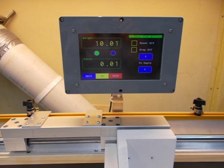
Prototype automation idea update
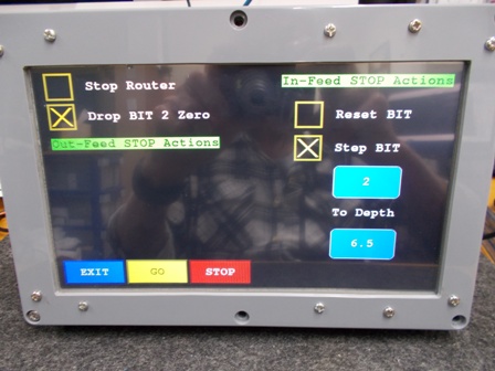
Quick view of the menu that will be used for Infeed and Outfeed fence stops with inbuilt sensors to automate fence stop actions.
In the picture below, when the JIG reaches the Outfeed stop it's set to drop the bit to zero (level with the top of the table).
When the JIG is returned to the Infeed stop position it steps the bit up 2mm from the previous work position ready for the next pass, it repeats this with each pass until the depth of 6.5mm is reached where it will drop the bit and turn the router off as the job is complete. Very quick and handy, I tried it out just now with two micro switches rigged up for the test and it was brilliant to use.
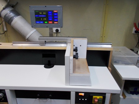
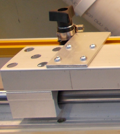
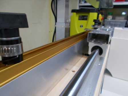
Below is the Right angle slide, there will be two quick release stops incorporated into the bearing rail when the key part I'm waiting for arrives. As mentioned previously, these two stops with inbuilt sensors detect when the jig has reached the outfeed stop position or had returned to the infeed stop position. This allows some simple automation for every day tasks.
 (1) Our small workshop layout __ (2) Bandsaw circle cutting jig __ (3) Spindle sander modifications __ (4) Dust Sensor
(5) Router table redesigned ____ (6) DC and where it all began __ (7) Bandsaw dust extraction build
-
23rd April 2019, 06:06 PM #64
Supporting my wife's hobby.
- Join Date
- Nov 2013
- Location
- Caboolture QLD AU
- Posts
- 781
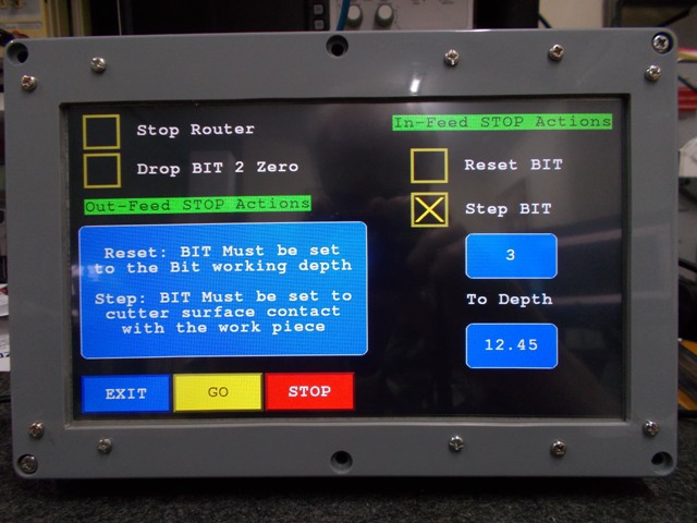
Small update to Feed stop menue
I jury rigged two stops with micro switches for the Fence mounted Right Angle Jig and carried out a lot of testing. I will post a small video when the real stops are installed. This is just so nice to use, and when required no more reaching for the router stop button.
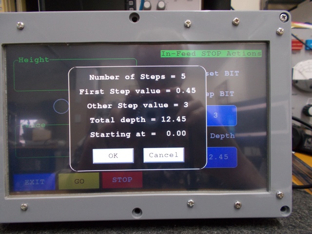
The pictures show some random values I entered and the results, I'm asking for 3mm steps to a depth of 12.45mm, when GO is pressed the next prompt window shows the resulting calculated settings to be used for that input, if OK is pressed the Last screen shown below appears.
 .
. 
Bit Height and Fence position are displayed along with two virtual LED indicators, LH is the Outfeed Sensor and RH is the infeed. Both Red = waiting for the RA Jig to be moved against the infeed stop to begin. After that the LEDs are like traffic lights, wait until the Feed-stop you have triggered with the jig turns from Red to Green before moving the RA Jig. I have speeded up BIT Height fast and fine movement logic so that average BIT set time is around one second.
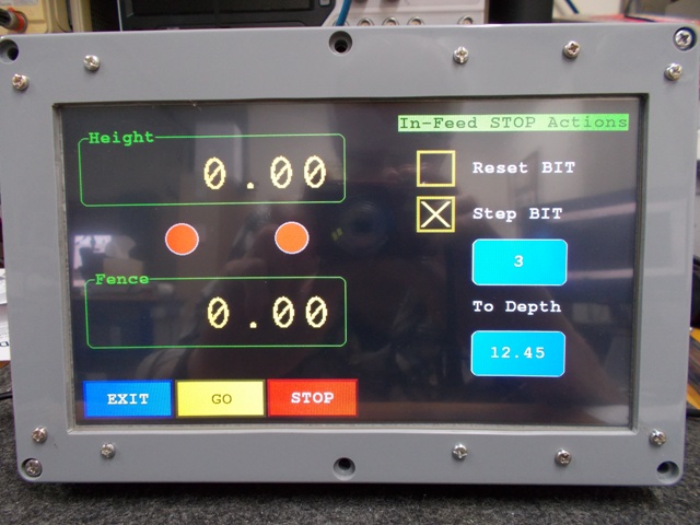
The options look simple - only 4 - but they cover a lot of my everyday tasks when two or more are combined.
No more dropping/lowering the workpiece onto the BIT to start a blind routing job, just enter how far you want to raise the bit into the workpiece with each pass and by how much and off you go. If you have the workpiece on the table and the Infeed Stop set (JIG against the stop), the bit will start as soon as you accept the displayed values.
There are more advanced automation options available for complex fence and bit movement work.
The RA Jig has proven to be so strong and accurate and such a Joy to use that I decided to grab a longer DRO and small readout to have a digital readout of the exact position of the JIG face relative to the Center of the BIT. Then I can accurately set the Infeed and Outfeed stops and take the Fence mounted version of the Table top Mitre slot into the digital age.
BTW NO WAY am I going to automate the RA slide or interface it into the main controller. I'm as happy as a pig in #$@% with how this has turned out. Do any more and you may as well build a full CNC.(1) Our small workshop layout __ (2) Bandsaw circle cutting jig __ (3) Spindle sander modifications __ (4) Dust Sensor
(5) Router table redesigned ____ (6) DC and where it all began __ (7) Bandsaw dust extraction build
-
25th April 2019, 01:09 PM #65
Supporting my wife's hobby.
- Join Date
- Nov 2013
- Location
- Caboolture QLD AU
- Posts
- 781
A Quick video of the Fence mounted right angle jig running on bearings blocks and linear rail, automated end stops (still a test setup at the moment using clamps with plastic jaws) are integrated into the Automation Controller.
The Feed Stop automation menu has the following options selected:
Infeed Stop actions
A: Step BIT
B: Step in 3mm increments.
C: To a depth of 8.75mm.
Outfeed Stop actions
A: Drop BIT to Zero.
When GO is pressed the software shows the number of steps and the adjusted first step to accomplish the task along with other settings show in a the previous screen shots.
At the end of each pass (Outfeed Stop reached) it drops the bit to below the table. When the JIG returns to the Infeed-Stop, the Bit is raised to the next position and the Virtual Green LED is lit. You can see the Infeed and Outfeed stop LEDS changing from Red to Green as each automation bit position is completed.
When the task has completed the Controller:
1: Stops the router motor.
2: Returns the Bit to the start position height.
3: Returns to the Feed Stop Menu.
FYI:
1: Any hunting of the last digit in the video is due to the DRO digital position data NOT being averaged in some automated modes, every decoded data packet is shown for maximum speed.
2: A rattling noise heard as the BIT is raised to the last position is caused by the insert ring vibrating. The Router Lift and Fence stepper motors cannot miss-step under ANY NORMAL condition in this table, you would have to wedge a screw drive into the bearings rails to cause a stall or miss-step.
EDIT: I just rewrote (again) the Code logic I used for display smoothing and virtually eliminated last digit hunting while maintaining high speed sampling for position.(1) Our small workshop layout __ (2) Bandsaw circle cutting jig __ (3) Spindle sander modifications __ (4) Dust Sensor
(5) Router table redesigned ____ (6) DC and where it all began __ (7) Bandsaw dust extraction build
-
25th April 2019, 01:31 PM #66
GOLD MEMBER
- Join Date
- Jun 2005
- Location
- Helensburgh
- Posts
- 7,696
I think that is fairly awesome and the icing on the cake, thanks Mike.
CHRIS
-
27th April 2019, 03:00 PM #67
Supporting my wife's hobby.
- Join Date
- Nov 2013
- Location
- Caboolture QLD AU
- Posts
- 781
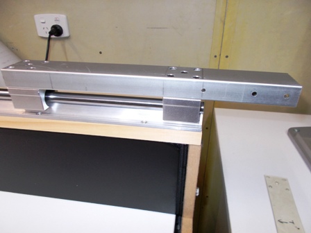
Simple adjustable Automated Fence stops
I wanted to come up with a robust, simple to make and simple to adjust set of Stops for my replacement version of the typical RT mitre slot. I realised there was no need to mount a micro switch or other sensor, these take up space and usually compromises the robustness of the stop and ease of adjustment, it was then I thought of using a simple version of a touch plate and a T-Track.
I used INCRA Regular T-Track because of its low cost and robustness, this was mounted to a length of 50mm square aluminium box section which is screwed down to the Mitre sled base plate, this removable Mitre Sled and Jig base plate is mounted to the top of the Basic main fence.
How the combined Feed Stop plate / Touch plate works:
The Linear bearing rail is steel with an aluminium mounting base, the two Bearing blocks have steel bearings in aluminium blocks and the bearing blocks are tied together with a 50mm x 25mm aluminium box section, all of this is electrically conductive from the Rail mounting base to the Box section.
So tying a ground common wire from the RT controller to the one of the Linear rail mounting screws makes the complete assembly a common ground reference point for the controller inputs.
Two thick aluminum Feed stop plates are screwed to the bearing block bridging box section, and are therefore also at common input ground reference. The Adjustable infeed outfeed stops are simply two INCRA T-Track bolts and knobs with insulated space blocks, once the stop are locked down to the T-Track, there is no way the slide assembly can move the stops when the thick stop plates contact them.
Now all that is needed to turn the stops into sensors is to attach a small metal hose clamp around the insulated spacer and connect a wire from the controller to each hose clamp. You now have a simple touch plate sensor in each stop. No moving parts, nothing to break and it works perfectly.
Below: One of the stops: That crappy hose clamp is one I had lying around, I just clamped a wire under it for this test as there are some very nice little sliding clamps available, I will get a couple on Monday to replace these. The other photo shows the Out-feed stop and stop-plate (touch plate), when the plate hits the adjustable stop and contacts the metal hose clamp it completes the circuit to ground, the controller can now act on the detected Stop input if required.
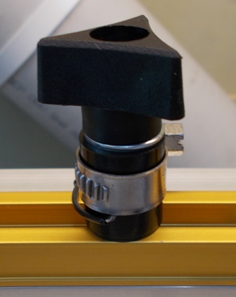 .
. 
Below: Yes I could have used just one Stop plate, I used two plates to keep the Lock knobs clear and out in the open. FYI note the virtual on screen LEDS for Infeed and Outfeed stops, the photos show the feed LEDs lit GREEN depending on which stop has been reached.
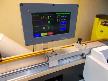 .
. 
Below: The INCRA T-Track mounted to the front edge of a 50 x 50 mm box section makes for a very strong stop system, I'll fit a stand alone DRO to the Slide to allow accurately setting the stops a breeze.
NOTE: In case it wasn't clear, there are no moving wires or electronics attached to the jig or bearing slide, it is simply a mechanical slide rail and Jig running on bearings and always indexed 100% to the fence.
 (1) Our small workshop layout __ (2) Bandsaw circle cutting jig __ (3) Spindle sander modifications __ (4) Dust Sensor
(5) Router table redesigned ____ (6) DC and where it all began __ (7) Bandsaw dust extraction build
-
28th April 2019, 09:56 AM #68
Senior Member
- Join Date
- Mar 2012
- Location
- South Gippsland
- Age
- 58
- Posts
- 103
I really love the simplicity and robust nature of this stop. It�s inspiring to see what a little lateral thought and ingenuity has led to overall. Simple and elegant! Thanks
Sent from my iPhone using Tapatalk
-
28th April 2019, 01:21 PM #69
GOLD MEMBER
- Join Date
- Jun 2005
- Location
- Helensburgh
- Posts
- 7,696
Mike, I think that is brilliant in simplicity, no switches to go wrong or vary in operation makes it a winner. How about a 3D printed stop on the linear rail with a metal connection to the rail for conductivity? will that work?
CHRIS
-
28th April 2019, 02:47 PM #70
Supporting my wife's hobby.
- Join Date
- Nov 2013
- Location
- Caboolture QLD AU
- Posts
- 781
Thanks Chris, it would work on the outfeed side however an infeed stop would not work on the Rail, as the picture shows, the box section extends off the table, the "off table" box section is where the Various fittings mount, in my case the Right angle jig, and obviously this allows you to move the face of the jig almost to the edge of the infeed side of the table. Originally Posted by Chris Parks
BTW: Since rewriting the controller software to adapt to all this extra automation, the Fence, and in particular the lift control, is now really slick.
Remember when we started out? The controller software was only going to implement a big combined display for two DRO scales and interface to some nice manual controls with a small amount of automation thrown in. The program has gone past 5500 lines of code and growing, but still blazingly fast with instant response to Sensor, Touch Screen and Manual control inputs, and still instant on. I'm starting to think of all sorts of additional uses, and especially after I do a spindle motor upgrade.(1) Our small workshop layout __ (2) Bandsaw circle cutting jig __ (3) Spindle sander modifications __ (4) Dust Sensor
(5) Router table redesigned ____ (6) DC and where it all began __ (7) Bandsaw dust extraction build
-
28th April 2019, 05:26 PM #71
Supporting my wife's hobby.
- Join Date
- Nov 2013
- Location
- Caboolture QLD AU
- Posts
- 781
FYI: When building the Fence and Lift automation, I spent countless time trying to get the Screw drives, Motors, Linear rails, Digital Scale slides and Fence all parallel to each other and the table top. Again with the lift getting the bearing rails 90� in all vertical directions to the Table top and so on. While I eventuality got it close to 100%, I wanted a simple way to do this sort of thing in future and a recent modest sale from TimbeCon on the latest version 3rd generation of the AngleCube was too tempting for me. I now have one and it makes this a breeze.
It has a resolution of 0.05�, accuracy of 0.2� and repeatability of 0.1�, Li-Ion rechargeable battery and Anodized alloy body with IP-54 rating and Rare-earth magnets on 3 sides. Great for checking things like bandsaw blade to table alignment. I simply placed it on the Router table and set it to zero reference, it's small and grips the bearing rails, screw drive shaft and motors while they are aligned and makes it a breeze to get everything running parallel and vertical in the table.
https://www.timbecon.com.au/measurin...be-bevel-gauge(1) Our small workshop layout __ (2) Bandsaw circle cutting jig __ (3) Spindle sander modifications __ (4) Dust Sensor
(5) Router table redesigned ____ (6) DC and where it all began __ (7) Bandsaw dust extraction build
-
28th April 2019, 07:26 PM #72
GOLD MEMBER
- Join Date
- Jun 2005
- Location
- Helensburgh
- Posts
- 7,696
I am building the two fence drive boards at the moment and I hope it is just a matter on getting the two boards fixed to the table referencing from the table top but if that doesn't work I will send the whole thing to you and drink a beer!
 CHRIS
CHRIS
-
29th April 2019, 08:56 AM #73
Supporting my wife's hobby.
- Join Date
- Nov 2013
- Location
- Caboolture QLD AU
- Posts
- 781
As you suggest, there should be no problems building it that way, being able to assemble the drive ends off table will make it simple to fit and align, obviously I didn't have that luxury with the first couple of Fence drive builds as I only had a rough idea of a design at that time, in practice I tried 3 variations until I found the best design for stability and accuracy. Trying to align each section while it's hanging off the side of the table is time consuming, and at times, not as easy as it would seem.
The big test with your build will be the influence of the Inverter on the Controller. If it does indeed cause corruption through the Plug pack supply, as BobL found in his pressure sensor build, then I won't worry about keeping it out of the plug pack, I'll make up an RF filter to fit between the plug pack 5v DC output and the Controller input.(1) Our small workshop layout __ (2) Bandsaw circle cutting jig __ (3) Spindle sander modifications __ (4) Dust Sensor
(5) Router table redesigned ____ (6) DC and where it all began __ (7) Bandsaw dust extraction build
-
29th April 2019, 09:59 AM #74
GOLD MEMBER

- Join Date
- Nov 2018
- Location
- Newcastle
- Posts
- 1,016
If you wanted a completely no-contact type stop, you could use a simple hall effect sensor and magnet, similar to that used on the axes of many 3D printers.
Bitluni did a simple youtube of his. Small variable resister to adjust the distance to the stop before it triggers.
https://youtu.be/9MegJCuHZjI
-
29th April 2019, 10:42 AM #75
Supporting my wife's hobby.
- Join Date
- Nov 2013
- Location
- Caboolture QLD AU
- Posts
- 781
Thanks for the thought, I have used Hall sensors in many other projects, however the biggest problem with proximity type sensors is their repeatable accuracy. The Limit / Feed Stops in this table have to be accurate to around 0.5mm or less as they are also used to set the exact size of T-Slots, Dados etc. I normally use optical sensors but a variation on a touch plates like this cost less than $3.
The only electronics needed are a HI-Z Darlington transistor and a couple of RC components, the Software takes care of any other artefacts. No adjustments and 100% accurate with no hysteresis or calibration, just can't get simpler. I use a Darlington input to give some protection for the IO pin on the micro and to ensure that the sensor operates even with dirty or tainted metal to metal contact.(1) Our small workshop layout __ (2) Bandsaw circle cutting jig __ (3) Spindle sander modifications __ (4) Dust Sensor
(5) Router table redesigned ____ (6) DC and where it all began __ (7) Bandsaw dust extraction build


 Reply With Quote
Similar Threads
-
Automated Guitars(s)?...or some such thing
By chrisb691 in forum MUSICAL INSTRUMENTSReplies: 5Last Post: 5th October 2012, 10:24 PM -
Automated milling and joinery
By BobL in forum SMALL TIMBER MILLINGReplies: 27Last Post: 17th May 2010, 11:39 PM -
Triton Router table RTA300 VS Carba-Tec Cast Iron Top Router Table
By pellcorp in forum TRITON / GMCReplies: 17Last Post: 30th April 2009, 02:43 PM
