

 Thanks:
  Likes:
  Needs Pictures: 0
 Picture(s) thanks:
Results 91 to 105 of 110
Thread: Automated Router table
-
9th June 2019, 08:33 PM #91
 Supporting my wife's hobby.


- Join Date
- Nov 2013
- Location
- Caboolture QLD AU
- Posts
- 781
 iGaging EZ-View scales fix.
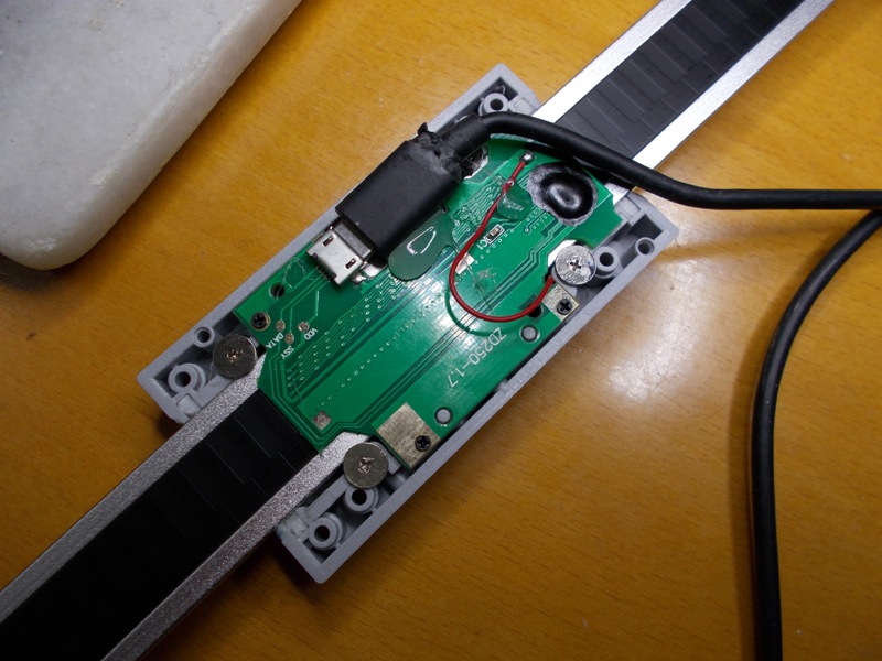
FYI for those using these scales. I Finally nailed the cause of random jumps and strange behaviour of my lift DRO after over 12 months of use, it only happened in a small part of the range but my Error catching code keep complaining that the DRO jumped more that 0.6 mm at the current speed and it could not have moved that far between reads, my controller read speed is 3 to 5ms per Scale, I'm reading the positions of two digital scales over 100 times a second or reading one over 200 times per second.
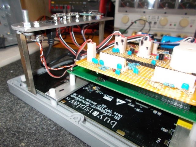
The problem turned out to be a spring loaded sliding copper grounding plate that sits below the Printed circuit board shown below. This copper brush earths the flat aluminium slide rail to the reader circuit board to complete the capacitive coupled reading circuit. The Red wire disappearing below the top RH side of the board (next to the screw) is soldered to the copper spring slide.
The inside of the scale was spotless, and even though it looked clean, I cleaned the copper brush and scale sides a number of times, the problem remained and I though the fault was elsewhere. I revisited it again when it came back with a vengeance, to prove my suspicion I soldered a very fine flexible wire to the red wire in the photo, I ran it out the same slot as the USB cable and clamped the wire under one of the scale rail mounting blocks.
Absolutely 100% perfect once again. To me this is the only weak link in these DROs. If mounted correctly the Plastic and aluminium DRO scale should last for years. but not that sliding earth connection. The fine wire I added does not get in the way in use and should outlive the DRO scale.
I've read many reports about the reading jumping around, problems with noise (true but that comes from the supplied scale head readout controller), my new 7" LCD touch screen controller has not had an electrical noise glitch EVER with these scales.
 (1) Our small workshop layout __ (2) Bandsaw circle cutting jig __ (3) Spindle sander modifications __ (4) Dust Sensor
(5) Router table redesigned ____ (6) DC and where it all began __ (7) Bandsaw dust extraction build
-
9th June 2019 08:33 PM # ADSGoogle Adsense Advertisement
- Join Date
- Always
- Location
- Advertising world
- Posts
- Many
-
2nd May 2020, 03:27 PM #92
Supporting my wife's hobby.
- Join Date
- Nov 2013
- Location
- Caboolture QLD AU
- Posts
- 781
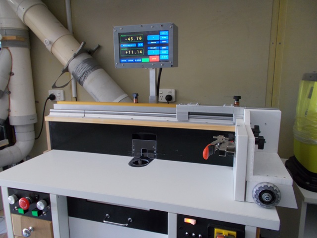
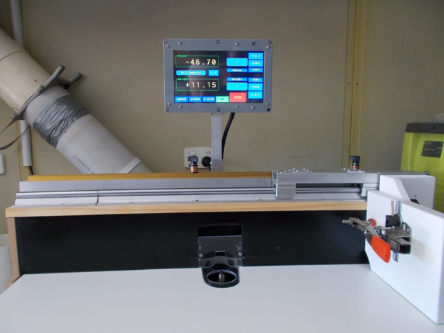
Been a long struggle getting back to the shed, I wanted to post a few photos of the final 9 inch Touch LCD RT Controller.
This unit has been designed to simplify my table wiring and future modifications / servicing.
Firstly, the new 9" controller mounted to the back of the Fence.
 . .
. . 
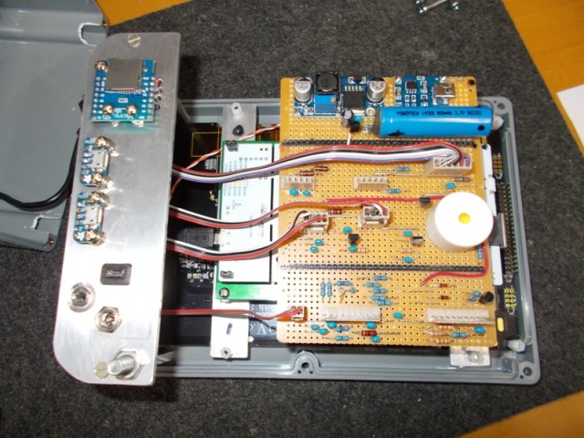
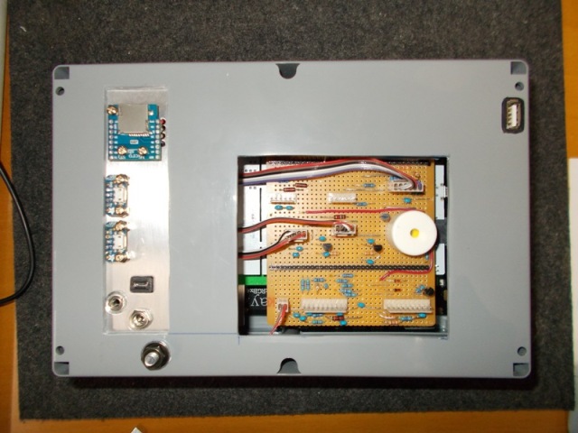
Below: The controller with the back case removed, the only internal wires are the few cables visible in the photo,
these cables connect two DRO sender sockets, SD card, Fence Stops and power connectors to the interface board connectors,
There is no other wiring in the Controller as the circuit boards simply plug together.
The Interface board plugs into main CPU board which in turn plugs into the LCD panel adaptor board. In this design, the DRO sender Backup battery, charger
module and DC input regulator are all mounted on the plug-in interface board. Nothing is attached to the back cover, the combined cable support / earth
bolt runs through the back panel. This bolt supports / locks down the single 28 core interface cable and earths the outer braid shield to a common earth frame.
 . .
. . 
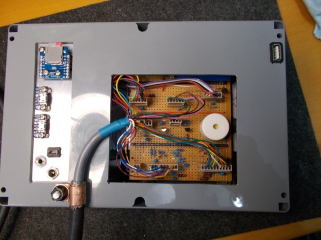
Below: Showing the back cover fitted, next Photo shows that single 28 core shielded interface cable plugged into the Interface board.
 . .
. . 
Below: The Cover plate fitted and a photo of the Interface cable with the attached Screw terminal Breakout header.
This now makes wiring the controller into the RT table a breeze.
 . .
. . 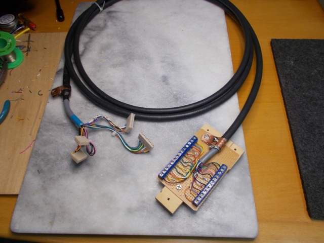
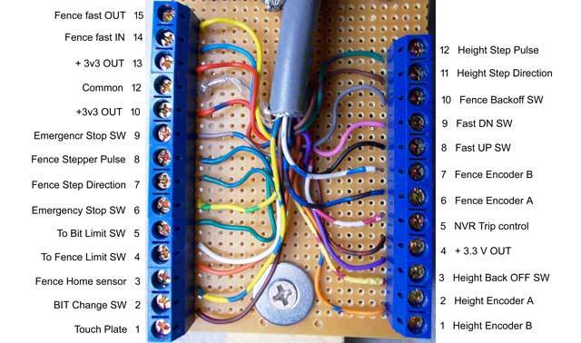
Below: And finally, the Breakout Header showing the connections to the various RT Sensors, Stepper motors, Manual controls and Limit switches.
The wires from the main cable are soldered to the pins of the screw terminal sockets, only the external connections are screw in, this type of screw
socket is like a mini vice, an external wire is inserted into a connector opening and is clamped between two smooth metal plates by a clamp screw.
Mike.(1) Our small workshop layout __ (2) Bandsaw circle cutting jig __ (3) Spindle sander modifications __ (4) Dust Sensor
(5) Router table redesigned ____ (6) DC and where it all began __ (7) Bandsaw dust extraction build
-
2nd May 2020, 10:06 PM #93
GOLD MEMBER
- Join Date
- Jun 2005
- Location
- Helensburgh
- Posts
- 7,696
Mike, I have to get back to mine but house renovations are taking up all my time at the moment and some stuff I ordered back in February still has not arrived. I need this to do the mounting boards for the spindle & fence drives accurately and more easily. I will be in touch shortly.
CHRIS
-
2nd May 2020, 11:41 PM #94
GOLD MEMBER
- Join Date
- Oct 2013
- Location
- Perth, Australia
- Posts
- 1,813
Fantastic work. Any chance you could do a video run down on the features at some point? There's so much to take in!
-
3rd May 2020, 11:54 AM #95
Member
- Join Date
- Apr 2013
- Location
- Mornington Peninsula
- Posts
- 70
Thanks for writing this all up. Fantastic project.
One question going way back to the beginning of the thread: Do you get any contamination of the slides and actuating thread/nut on the router lift from routing chips and dust? Is the acrylic shield together with the dust extraction sufficient to keep everything clean and running freely with extended use? I would have thought bellows or better shielding was necessary - but I tend to over complicate things...
Leigh
Sent from my iPad using Tapatalk
-
3rd May 2020, 12:37 PM #96
Supporting my wife's hobby.
- Join Date
- Nov 2013
- Location
- Caboolture QLD AU
- Posts
- 781
Thanks, I've posted a few poor videos in the past, however they pale in comparison with how great it actually is to use in real life. But once (if) I get back to health, I'll try to do a full overview. Originally Posted by bueller

One of simplest things I came up with was that fence mounted sliding Linear Rail mitre sled, as it's always indexed to the fence and moves with the fence, it opened up a host of automation tasks, like automated box joints. Even with professional videos from manufactures showing their own mitre jig in use, you can see them fighting that slight friction generated by typical mitre slot guided jigs. What I can't convey in a video is the unbelievable feel you get for the cutter to workpiece load and cutting forces with a zero friction slide, and the safety of a locked down slide.
That led me to an idea to make simple instantly adjustable feed stops, I then realised I could automate the Infeed and Outfeed stops.
Some jobs that required you to lower a workpiece onto the running bit (plunge) are a thing of the past, automated lowering of the bit below the workpiece when the sled engages the Outfeed stop and automatically raising of the bit when you return to the Infeed stop, make working on this table a joy, but that's also a very real safety feature, as is automatically stopping the Router / Spindle motor on completion of a cut if needed. Making a blind slot in thick timber with a number of incremental depth cuts on each pass is simple when the stepped Bit depth is fully automated in conjunction with the Feed-Stop sensors. (apology for rambling on, I've been in solitary confinement for so long)
Mike.(1) Our small workshop layout __ (2) Bandsaw circle cutting jig __ (3) Spindle sander modifications __ (4) Dust Sensor
(5) Router table redesigned ____ (6) DC and where it all began __ (7) Bandsaw dust extraction build
-
3rd May 2020, 01:20 PM #97
Supporting my wife's hobby.
- Join Date
- Nov 2013
- Location
- Caboolture QLD AU
- Posts
- 781
Hi Leigh, not really, a 150mm exhaust and a 3hp DC with all hard line ducting makes a huge difference. However, I was constrained by the modified Router when building the Lift, I will be changing over to a spindle motor and VFD when I can save enough, that will allow me to get an even better flow path and move the linear rails in a fashion that allows for an almost complete encasing of the extraction path around the top of the spindle and bit. Just to be on the safe side, I've only had to hit the bearing blocks with a squirt of dry lubricant twice in the past two years, still look clean. The screw drive never gets a speck of dust on it as it's front mounted. There are no traces of chips or dust in the lower cabinet. Originally Posted by Ambrosia
I've briefly mentioned somewhere that there is no real need for Fence dust extraction with this design of insert plate (open behind the bit), basically it means that the Fence cut-out only needs to cater for the maximum bit height and depth into the fence for the largest bit used. Most Fence extraction appears to be beneficial ONLY because below table (through the bit) dust extraction is so compromised in typical router tables. Once you get bit extraction working (opened up behind the cutter) Fence extraction becomes redundant, further, Fence extraction is irrelevant once the fence moves back a short distance from the Bit, or when the Fence is blocked by a taller workpiece, or if the cutter is completely covered by the workpiece (blind cuts).
Another thing that suddenly shows up more when really good Bit dust extraction is achieved, is the extra workpiece stiction created by increased air flow, now this can be negated and actually used to our advantage by modifying the Table top. This takes us down a new path that's fortunately been opened up by the fact that the Table top can be made light weight, does not need to be screwed to the Router cabinet (can just lift off), does not need a router insert mounting plate and does not support any part of the Lift mechanism and router / spindle motor, thus allowing the top to be easily modified to take advantage of bit extraction and stiction relief used to increase dust extraction below and around the work piece. Ah! it never ends
Mike.(1) Our small workshop layout __ (2) Bandsaw circle cutting jig __ (3) Spindle sander modifications __ (4) Dust Sensor
(5) Router table redesigned ____ (6) DC and where it all began __ (7) Bandsaw dust extraction build
-
3rd May 2020, 03:38 PM #98
Supporting my wife's hobby.
- Join Date
- Nov 2013
- Location
- Caboolture QLD AU
- Posts
- 781
Hi Chris, uploaded the draft V2 Manual in PDF format, quite a few hyperlinks in there to make navigating a bit quicker, almost every screen grab of the Controller menus are in there. I will do a linked index when I'm up to it, also more setup and build info to come, I'll let you know whenever it's updated. Originally Posted by Chris Parks
User manual V2.pdf *** Updated 04/05/2029 11:55AM.
Mike.(1) Our small workshop layout __ (2) Bandsaw circle cutting jig __ (3) Spindle sander modifications __ (4) Dust Sensor
(5) Router table redesigned ____ (6) DC and where it all began __ (7) Bandsaw dust extraction build
-
4th May 2020, 05:16 PM #99
GOLD MEMBER
- Join Date
- Jul 2011
- Location
- In between houses
- Posts
- 1,784
That is one of the best shop built machines I�ve ever seen.
-
4th May 2020, 05:39 PM #100
Supporting my wife's hobby.
- Join Date
- Nov 2013
- Location
- Caboolture QLD AU
- Posts
- 781
PDF draft Manual updated with hyperlink index.
User manual V2.pdf
It May take some time for the Cache to reflect the new file.
Mike.(1) Our small workshop layout __ (2) Bandsaw circle cutting jig __ (3) Spindle sander modifications __ (4) Dust Sensor
(5) Router table redesigned ____ (6) DC and where it all began __ (7) Bandsaw dust extraction build
-
4th May 2020, 08:22 PM #101
Member
- Join Date
- Apr 2013
- Location
- Mornington Peninsula
- Posts
- 70
Mike,
You mention that there have been very few skipped or erroneous steps (on the steppers). Would it be possible to achieve acceptable levels of accuracy without the DRO feedback - simply counting steps to determine position? The DROs seem to add quite a lot of complexity.
Leigh
Sent from my iPad using Tapatalk
-
5th May 2020, 09:31 AM #102
Supporting my wife's hobby.
- Join Date
- Nov 2013
- Location
- Caboolture QLD AU
- Posts
- 781
Hi, the context of skipped steps was in relation to driving two motors in parallel from the one Stepper drive controller, something that is often frowned upon, if there was a missed step in either motor, then in this design, the Fence would start to skew, fortunately, I was aware of the limitations of stepper speed (parallel drive) and ensured the motors and driver were more than capable of moving the Fence under any encountered load condition without stalling.
Just thinking out loud here, I suppose it also depends on what part of the build process we define as complex. From a purely mechanical perspective, these are just about the easiest feedback devices to mount in the router table. If you only wanted to have manual controls and build a low cost Router Lift, and possibly have the Fence "motor driven", then you only need to use the supplied Head display units that come with each DRO to visually display the position.
As far as interfacing and reading this type of DRO with a micro controller, these units are relatively simple as you are dealing directly with real position data during calculations. Counting pulses would require constant conversion to relative position, that in itself adds another level of complexity to programming and hardware, and you would still need a motor position feedback device to ensure that the stepper motor actually did step when requested. Using a precision pulse output Digital Slide Scale usually requires a separate interface board for accurate pulse decoding, and they are usually more critical with respect to mounting. There are simpler optical encoders available for motor shaft position feedback, but again, deciding on the best way to count high resolution pulse outputs from two devices in real time with a simple micro controller, which is also monitoring a number of sensors and calculating the automation and display output tasks, might require more expense in the controller hardware compared to using these relatively low cost and extremely accurate (for this task) Digital slide scales.
Once again, algology if I appear to be rambling on, or misunderstood the question.
Mike.(1) Our small workshop layout __ (2) Bandsaw circle cutting jig __ (3) Spindle sander modifications __ (4) Dust Sensor
(5) Router table redesigned ____ (6) DC and where it all began __ (7) Bandsaw dust extraction build
-
5th May 2020, 10:12 AM #103
GOLD MEMBER
- Join Date
- Jun 2005
- Location
- Helensburgh
- Posts
- 7,696
When we began putting the control side of the router table on my Hammer A3 my son asked the same question, if a 3D printer can rely on the step count from the motor why can't the same method be used for control on the A3 combination machine and the RT.
To remove the confusion a few years ago I asked Mike to design a target dimension system for my A3 combination machine and somehow it got shoved aside and the RT became the project. We now have installed the system on the A3 but for a lot of reasons it had to be removed and due to life's little hurdles has not gone back onto the machine, this I hope will happen in the next few months.
For the back story use the link in Mike's signature to his posts.CHRIS
-
13th August 2020, 08:23 PM #104
Member
- Join Date
- Aug 2015
- Location
- Victoria - Ferntree Gully
- Posts
- 53
Mike thankyou for posting all of your work, its given me the courage to give it a go myself! Not sure that it will be up to your standard, but will give it a go anyway.
-
18th August 2020, 06:40 PM #105
SENIOR MEMBER
- Join Date
- Aug 2006
- Location
- Canberra - West Belco
- Age
- 63
- Posts
- 646
Mike, many thanks for the thread, the ideas and the hard work undertaken, it has been a while since the last update so i hope you are well or as well as you can be.
One thing in all the reading is i have not spotted any link or details on how to get the software and i noticed when i jumped over to element14 to check pricing on the dev board that it states no longer in production even though they have plenty of stock, is there a newer alternative perhaps? I used to do Microchip based controllers for a different hobby and the end of life products are a pain in the butt.....
Cheers
Phil


 Reply With Quote
Similar Threads
-
Automated Guitars(s)?...or some such thing
By chrisb691 in forum MUSICAL INSTRUMENTSReplies: 5Last Post: 5th October 2012, 10:24 PM -
Automated milling and joinery
By BobL in forum SMALL TIMBER MILLINGReplies: 27Last Post: 17th May 2010, 11:39 PM -
Triton Router table RTA300 VS Carba-Tec Cast Iron Top Router Table
By pellcorp in forum TRITON / GMCReplies: 17Last Post: 30th April 2009, 02:43 PM
