

 Thanks:
  Likes:
  Needs Pictures:
  Picture(s) thanks:
Results 241 to 255 of 264
Thread: Yet another Router table build.
-
24th July 2018, 07:46 PM #241
 Supporting my wife's hobby.


- Join Date
- Nov 2013
- Location
- Caboolture QLD AU
- Posts
- 781

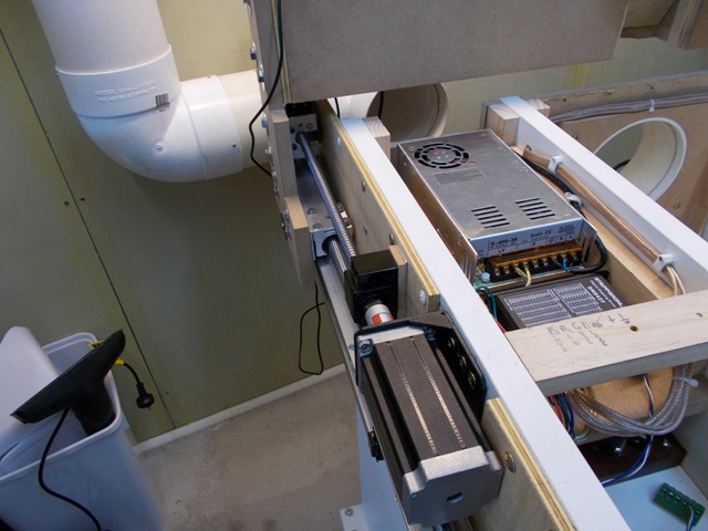
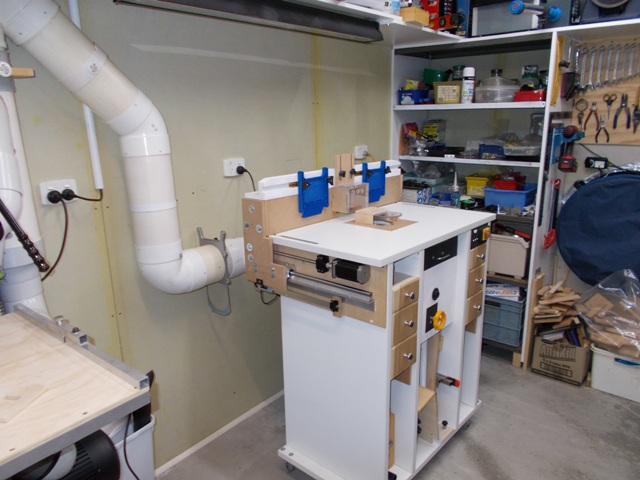
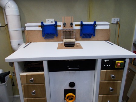
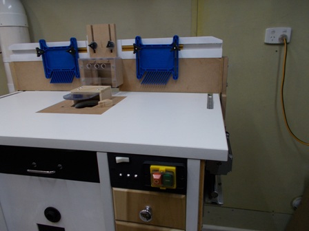
The Fence moves back behind the Table top and allows me to simply lift the top off, this gives complete unhindered access to everything including the drive units that are normally tucked right up under the table overhang on each side. the Fence can be run as if the Top was on, this is another plus when setting up or modifying the table.
The Table top does not have to be bolted down in any way, it is designed to slot into the open top and lock in the same position every time. The easiest I've ever had to work on, when the fence is cleaned up and finished I will never need to remove the fence again.
This is the power supply and driver module for the stepper motors, heat and ventilation is not a problem despite what appears to be a cramped and not ventilated area, it is neither.
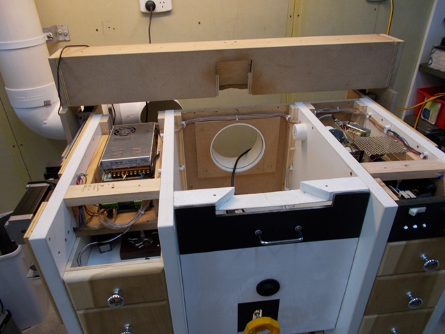
Total access with the table removed, it simply lifts off after the fence is moved back off the back off the table. That left hand open space above the draw (seen clearly in the photo above) is where the Manual JOG buttons and Encoders for the Fence and Lift will go, a total of 4 controls. The stepper drive units for the Fence are wired up and the only thing missing is the display and control micro.
With the Fence off the back of the table there is plenty of room for various free hand slot in jigs.
Not the greatest picture but everything looks clean and tidy.
 -
- 
The result of some more testing to follow.(1) Our small workshop layout __ (2) Bandsaw circle cutting jig __ (3) Spindle sander modifications __ (4) Dust Sensor
(5) Router table redesigned ____ (6) DC and where it all began __ (7) Bandsaw dust extraction build
-
24th July 2018 07:46 PM # ADSGoogle Adsense Advertisement
- Join Date
- Always
- Location
- Advertising world
- Posts
- Many
-
24th July 2018, 08:18 PM #242
Supporting my wife's hobby.
- Join Date
- Nov 2013
- Location
- Caboolture QLD AU
- Posts
- 781
I tried to reconnect a DRO and small OEM head unit to back centre of the fence, this is where I had it before, I wanted to confirm the readings and any play in the system, I failed to do so as the readings were out by up to 4 mm, but not all the time, I soon realised that my temporary connection and mounting was not good enough to measure correctly.
So out with the big Lufkin steel rule and clamped it beneath the fence (the fence just grazes over it) that is what proved that this new fence position system was spot on, there was no visible discrepancy over the entire length 280 mm travel of the Fence. The rule is marked in 0.05 mm steps and I could move multiple 0.05 steps and always land on the mark. Now of cause someone will point out that these rulers are out my 10 mm and are only a rough guide, it's good enough for me until I can connect a more accurate device to the table.
One thing it did prove again is that the .01 mm to .03 mm deflection I see when pressing hard against the fence is indeed the fence bowing slightly, this is a seriously braced and heavy fence as this was the problem I had when I first installed a DRO, only it was far worse until I built this Fence, I can live with it and at my age I can't even see that any more. What it also showed was no movement at either end of the fence.
As shown in the previous photos, the Fence drive system is wired up and the power supply and Driver module are installed, I plugged in the Micro controller and spend a good hour testing and never once did the dual drive skip a beat, because the available current is limited to 2.1 A per motor, if one hits a stop or jams, they both skip and sort of stop as the current limit trips, There is enough power in the fence to push a car battery across the table top without any change in the sound from the motors, so that unscientific test is good enough for me as well.
I have some yard work and some filters to install on the Dust extractor so won't be starting on the Router lift until then.
I have a poor video attempt that I might post of the slide moving across the table, it was taken as an afterthought after I had removed the rule and pointer setup, so I just popped the rule back under the fence (not the centre as I had removed the pointer setup for that location) to give a rough idea.
Part 1:
Part 2:
(1) Our small workshop layout __ (2) Bandsaw circle cutting jig __ (3) Spindle sander modifications __ (4) Dust Sensor
(5) Router table redesigned ____ (6) DC and where it all began __ (7) Bandsaw dust extraction build
-
25th July 2018, 09:43 PM #243
Supporting my wife's hobby.
- Join Date
- Nov 2013
- Location
- Caboolture QLD AU
- Posts
- 781
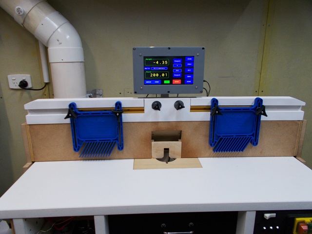
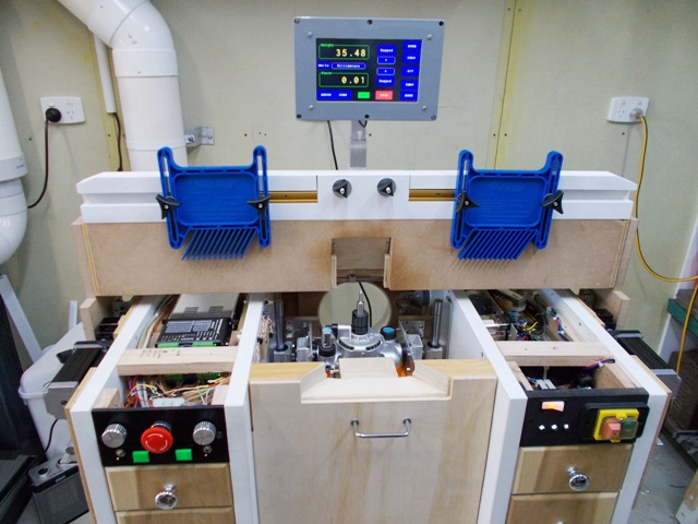
Managed to finished the Fence automation installation, the display is mounted to the back of the fence, obviously it follows the fence and is both height and depth adjustable, it's a really solid mount of box aluminium, doesn't vibrate or move in any way when using the touch screen. It's a perfect position to see and operate and really puts the focus where you are working. Actually looks 100 times better when you see it in the flesh, those visible cables will not be there when the display controller is finished. The cables do not drag along the table, they run along the back of the fence to one end plate, down the back of the end plate and then loop into the back of the router table, this also means there is no loop or tension in the DRO slide cable as the slide moves with the end plate, so a really tidy installation and solution. Can't wait to start on the router lift as that is going to be so simple when compared to the Fence.
 (1) Our small workshop layout __ (2) Bandsaw circle cutting jig __ (3) Spindle sander modifications __ (4) Dust Sensor
(5) Router table redesigned ____ (6) DC and where it all began __ (7) Bandsaw dust extraction build
-
30th July 2018, 09:42 PM #244
Supporting my wife's hobby.
- Join Date
- Nov 2013
- Location
- Caboolture QLD AU
- Posts
- 781
As mentioned a few pages back, a new thread will be created for this motor driven Fence and Router lift when it's finally completed. It's actually getting close with only the router lift to finish. I was initially going to rebuild the router table but on reflection I found that this table, with some extra bracing to allow for the freely removable table top, is just fine for the task.
This current thread is for testing some ideas and just putting stuff out there for thought and comments on a better way to accomplish the conversion. So to add to these ideas, I've been thinking about the Fence and router lift limit switches after using and testing the fence for some time. For those new to Stepper motors connected to screw drives or other toque multiplying / speed reduction systems, there is a need to cut the drive to the stepper motors if the Router lift or Fence in this case, tries to travel past the end of the bearing rails or the drive physical limits of travell. This can happen due to a fault, noise glitch or operator error, because of the torque and drive force introduced / enhanced by the reduction drive, some damage can be done to mechanical parts.
As a fail-safe, a simple Micro switch is fitted to detect excessive travel at each end of the drive system, normally these switches are simply wired to the Enable line on the Stepper Drive controller. If the Micro-switch is tripped, the Enable line is removed and all power to the stepper motor is cut. There is one problem with this system, you have to manually move the drive shafts to back the router or fence away from the stop (micro switch) until the switch deactivates and the Enable line is restored.
When I designed the Software for the Micro controller I included a Limit switch sense input for the Fence and Router Lift. For fail safe and safety reasons, the Enable line and micro-switch circuits are independent of the Micro controller, however these extra Limit sense lines I included tell the Micro controller that the Fence or Router Lift limit switch has been tripped.
So why do this? The Limit Sense lines serve two tasks, the first task is to halt AND cancel all drive commands from the Micro controller. Secondly, it allows the use of a simple push button switch on the manual control panel, this switch does two things when pressed - IN.
1: It unblocks the Enable line allowing power to the stepper motors.
2: The Push-button switch also signals the Micro controller to activate a slow speed pulse train to the Stepper in the REVERSE direction of travel from what caused the Limit switch to trip, at the same time the Micro monitors the Micro switch and when the switch is no longer triggered it disengages slow reverse, slow reverse is also disengaged if the manual push-button switch is released.
So you have safe manual override control of a Fence or Router lift that is hard against the End stop. The correct direction of travel is selected for you by the Micro controller and you no longer have to get under the table, or each side of the dual fence drive system, to rotate the motors away from the micro switches.
There are 22 control lines (I/O pins) interfaced into the Micro-controller that control the Fence / Router lift automated drive systems. The plan with a new thread is to have the block control system shown along with the mechanical parts used and the table construction.
BTW I also realised that there is no need to ramp down the Fence to a stop as there is no real momentum in the fence system, so for the manual Fence forward / back switch, I've removed the slow ramp down speed, there is still a quick ramp up to speed, and the automated go-to x.xx mm position is still slow ramped down for ultimate accuracy.
All that extra interfacing and control actually make, what would be a complex system, extremely simple to use.(1) Our small workshop layout __ (2) Bandsaw circle cutting jig __ (3) Spindle sander modifications __ (4) Dust Sensor
(5) Router table redesigned ____ (6) DC and where it all began __ (7) Bandsaw dust extraction build
-
4th August 2018, 06:01 PM #245
Supporting my wife's hobby.
- Join Date
- Nov 2013
- Location
- Caboolture QLD AU
- Posts
- 781
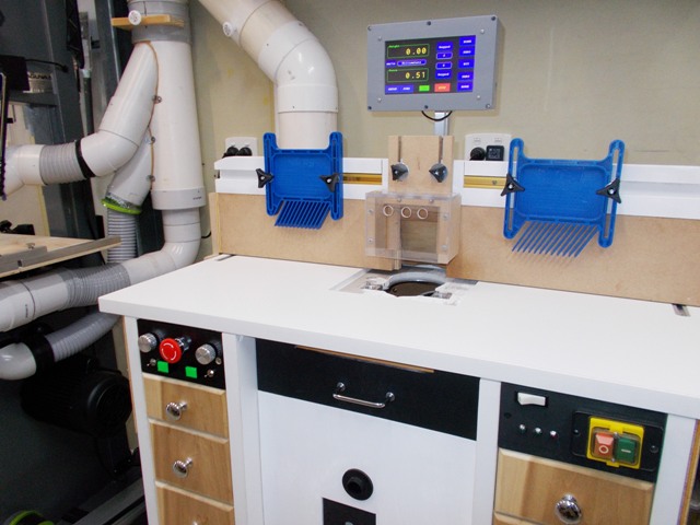
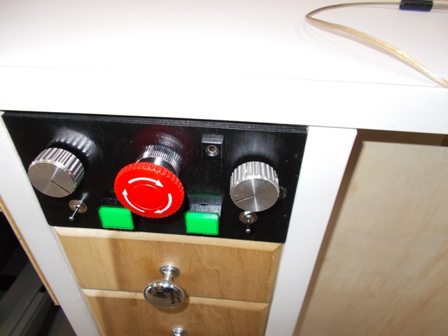
Health issues have stopped me building the Router Lift, however I've spent the time finishing the Manual Control Panel. The two sliver knobs are the Rotary encoders for adjusting Fence position and the Router height, both allow 0.01 mm fine adjustment per step. The Green buttons light up if either the Fence or Router lift drive mechanisms trip a limit switch.
The illuminated Green button is pressed and it automatically backs off the associated Limit switch, the switch light goes out when the limit micro switch is no longer on. The Big red button is a locking Safety emergency stop switch. Rotating the Red knob reset the switch to off. Most of this was explained briefly in the previous post. Everything is now wired up with only the Lift Stepper motor and it's two Limit switches to be connected. Hoping to have the Router / Spindle Lift running by the middle of next week.
 -
-  (1) Our small workshop layout __ (2) Bandsaw circle cutting jig __ (3) Spindle sander modifications __ (4) Dust Sensor
(5) Router table redesigned ____ (6) DC and where it all began __ (7) Bandsaw dust extraction build
-
9th August 2018, 05:39 PM #246
Supporting my wife's hobby.
- Join Date
- Nov 2013
- Location
- Caboolture QLD AU
- Posts
- 781
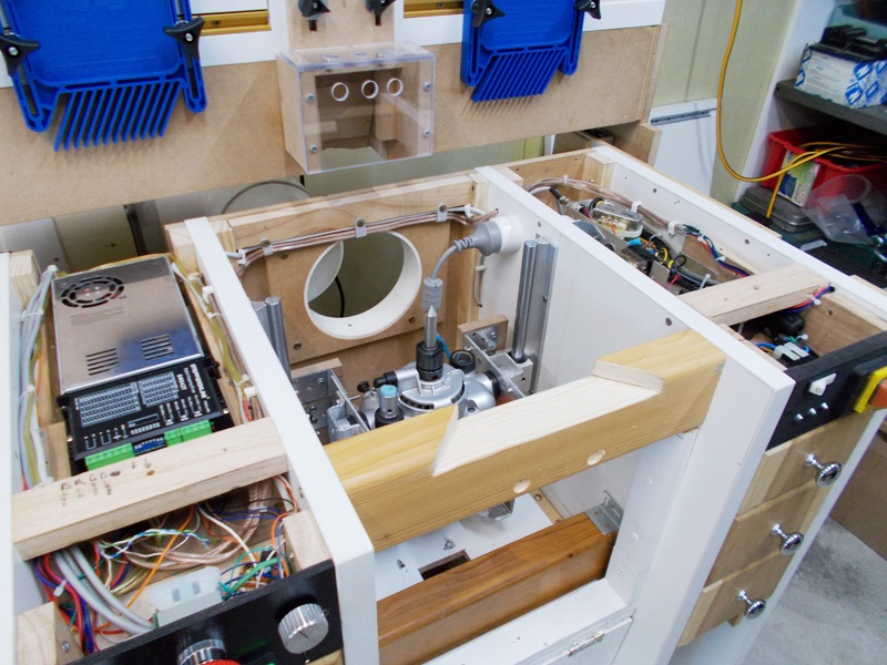
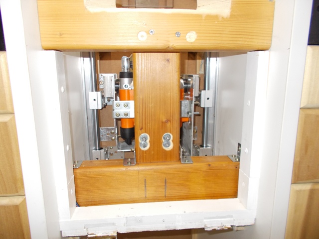
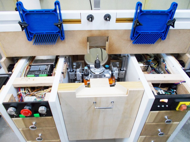
Started on the Router lift today and just ran out of time to fit the Stepper drive system, so here are a few WIP shots.
1: This table is being designed with a Spindle motor in mind, however I'm using a triton router that I've modified to work without a base plate.
2: This is a test build of the Lift as the only way to see if it works as intended is to try it. Any flaws will be corrected in build two, although it's looking like I won't need to rebuild it until I get a spindle motor as it's so dam good even when fashioned from MDF and metal brackets that I had laying around.
3: I've been testing various positions for the Screw drive and I'm satisfied that my original layout idea works, so tomorrow I should have the stepper and drive installed and running.
4: The only resistance to vertical movement is the router weight itself, in other words, the bearing slide rails are working as intended, this is a far cry from the routers own guide tubes.
5: The router now feels as solid as, especially when compared to the slight movement / flex that was apparent in the Routers own guide tubes system, I'm sure that some routers are better in that regard than the triton I'm using.
6: During the testing, I have not had one glitch in the Control micro reading the Digital Scale slides, all the wiring and electronics are installed, also finished the Scale memory backup as these scales are not Absolute position and need a battery backup as previously discussed in the the first part of this tables evolution.
BTW: The electronics on the right of the router table have always been there, they are for safe control of the Router along with Dust extraction detection and NVR and are not part of this fully automated Fence and Lift installation.
 -
-  (1) Our small workshop layout __ (2) Bandsaw circle cutting jig __ (3) Spindle sander modifications __ (4) Dust Sensor
(5) Router table redesigned ____ (6) DC and where it all began __ (7) Bandsaw dust extraction build
-
10th August 2018, 06:32 PM #247
Supporting my wife's hobby.
- Join Date
- Nov 2013
- Location
- Caboolture QLD AU
- Posts
- 781
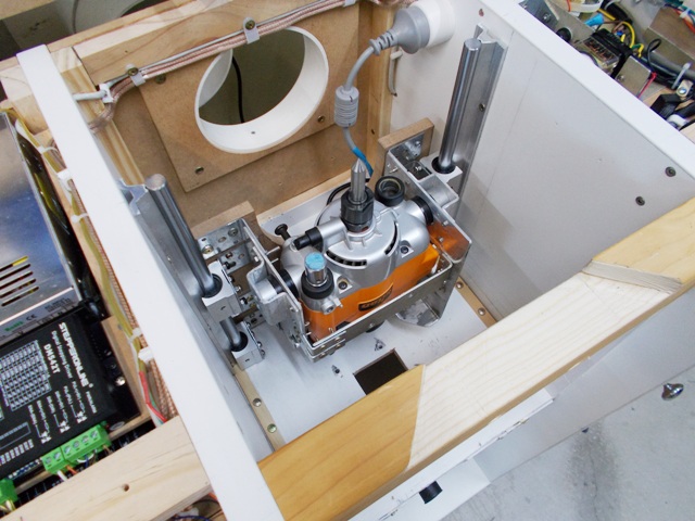
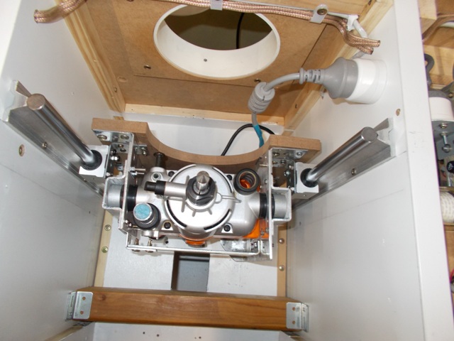
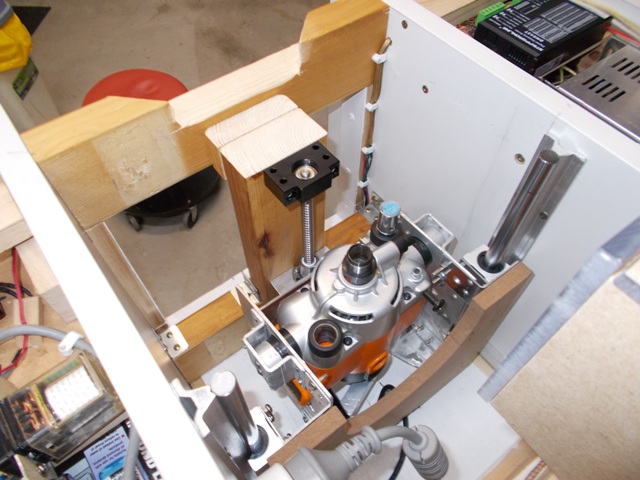
Frustrating slow day, just fit a motor and screw drive, how hard can it be? Well the problem is alignment, so very time consuming but a few minutes ago I had the lift working.
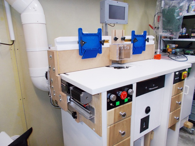
I'll do a video tomorrow but it's rock solid, no movement anywhere, works as smooth as silk. Again a few WIP pictures, this also show the tripod layout I used to make this lift so strong and movement free, this is a departure form having the drive on the same side as the bearing rails, with this layout the Router or spindle motor is not hanging off the back plate, it's fully supported on all sides.
Haven't fitted the limit switches or Scale slide yet, but thats just a bit of fiddling around tomorrow.
The weight of the router and drive is supported by three thick Pine bearers, The vertical bearer is a step join onto the lower bearer, that could lift the entire cabinet and also braces the side walls, as does the top thick pine bearer. The screw drive support bearing is bolted to this vertical bearer.
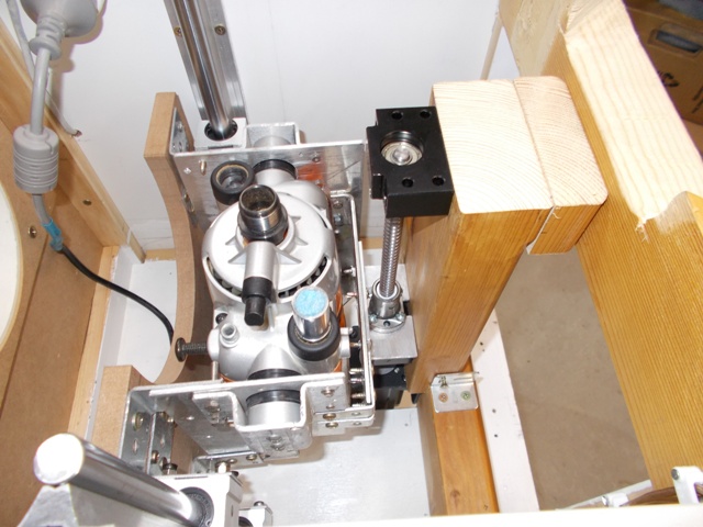
Through the cabinet door opening, none of these bearers inhibit air flow as cabinet air flow is through the vent cut into the top bearer. Also there is no restriction to cabinet access as the top is completely removable.
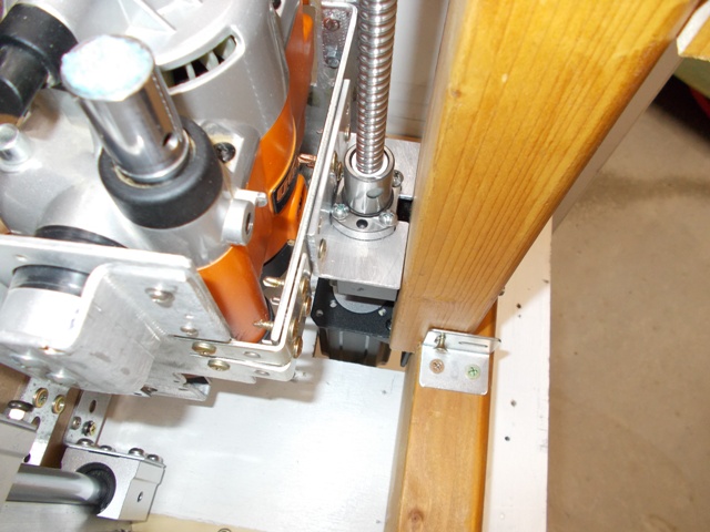
View from behind the fence.
The Stepper motor goes through the upper cabinet floor by about 50 mm, wires run under the upper cabinet floor, also note the Ball-nut bearing connected to a bracket that ties it to the router frame, just below that is the main load bearing.
 (1) Our small workshop layout __ (2) Bandsaw circle cutting jig __ (3) Spindle sander modifications __ (4) Dust Sensor
(5) Router table redesigned ____ (6) DC and where it all began __ (7) Bandsaw dust extraction build
-
10th August 2018, 07:50 PM #248
GOLD MEMBER
- Join Date
- Jun 2005
- Location
- Helensburgh
- Posts
- 7,696
Not a lot of superfluous stuff left on the router is there!
CHRIS
-
10th August 2018, 08:08 PM #249
Supporting my wife's hobby.
- Join Date
- Nov 2013
- Location
- Caboolture QLD AU
- Posts
- 781
Hi Chris, no just one post but it's not in the way, just about to spend an hour or so mounting the Digital slide and limit switches, getting close to the end, I'm trying an optical sensor for the fence zero sensor over the weekend, I've decided on a touch plate for the Bit zero, that also allows you the option of setting the bit cutting surface height quickly and accurately when required. Also watching the Router lift smoothly micro adjust with the Rotary encoder is impressive - and with zero backlash.
(1) Our small workshop layout __ (2) Bandsaw circle cutting jig __ (3) Spindle sander modifications __ (4) Dust Sensor
(5) Router table redesigned ____ (6) DC and where it all began __ (7) Bandsaw dust extraction build
-
11th August 2018, 05:57 PM #250
Supporting my wife's hobby.
- Join Date
- Nov 2013
- Location
- Caboolture QLD AU
- Posts
- 781
Just did the first quick test cut on the table. Here is a very quick video that shows the Router Bit (lift) and Fence being set to a pre-set Job position, the position that I did the test cut on. The only things left to finish are the Bit sensor plate and the Fence Zero sensor. It's soooooo nice and smooth. I can also utilize the auto Chuck Lock on the Triton, but I need to put a micro switch to cut power to the router once I go past the normal bit working point, Why? There is no power on/off lockout as the posts that interlock the on/off switch are not even in my modified triton router.
BTW I have the fence way back so you can see the Bit move down.
(1) Our small workshop layout __ (2) Bandsaw circle cutting jig __ (3) Spindle sander modifications __ (4) Dust Sensor
(5) Router table redesigned ____ (6) DC and where it all began __ (7) Bandsaw dust extraction build
-
12th August 2018, 06:00 PM #251
Supporting my wife's hobby.
- Join Date
- Nov 2013
- Location
- Caboolture QLD AU
- Posts
- 781
As noted in earlier posts, the Control micro Touch screen had a button labelled "BIT" for automatically sending the router to the Bit change position, I implemented that today and with the Triton router I added a metal ramp to implement the router auto shaft lock mechanism.
I added an adjustable micro switch that switches on when the correct collet change height is reached, which is about 2 mm before the standard fail safe Limit micro-switch trips.
Some would think "why not just use the limit switch?" As I posted before, this Limit switch is a hard wired switch independent of the Micro controller and cuts power to the Stepper motor via the Stepper digital drive unit. That means that the only way to move the stepper motor (lift) back from the limit switch is to manually turn the motor shaft or bypass the safety micro and power everything in the correct direction. This is not the case with the Bit change Switch as the Micro controller simply stops the Stepper motor (lift) under Software control 2 mm from the Limit switch, so I'm back to a single one handed bit change.
What's interesting is that the Software and simple micro switch are always within 0.04 mm of the same position every time. I've just carried out a brief test of the optical sensor for Fence Home position and it looks like a goer. Using this type of sensor means that the fence always knows if it's past the sensor or before the sensor when you press the "Fence Home" button and the software sets it accordingly. Best of all the sensor is only $6.00.(1) Our small workshop layout __ (2) Bandsaw circle cutting jig __ (3) Spindle sander modifications __ (4) Dust Sensor
(5) Router table redesigned ____ (6) DC and where it all began __ (7) Bandsaw dust extraction build
-
13th August 2018, 04:10 PM #252
Supporting my wife's hobby.
- Join Date
- Nov 2013
- Location
- Caboolture QLD AU
- Posts
- 781
Fence Home sensor is finished, I can confirm that these low cost optical sensors are extremely accurate at edge detecting. The sensor consists of a photo sensor and led light source in a single tiny housing, there is a slot in the housing that separates the light path, when the path is interrupted the output changes, they only need 3 wires, ground, supply and output.
I have fitted a small aluminium slide that moves into the optical path when the fence reaches the exact centre of the router chuck - and it's adjustable.
Some interesting findings:
1: The Optical Sensor is mounted at the bottom of the fence side plate, below the stepper motor.
2: This fence Home position is not using the Digital scale for any position data, the software simply displays the scale reading when the sensor is tripped.
3: This means that any mechanical movement, backlash, play or whatever you want to call it in the lower fence system will be glaringly obvious on the display readout and more importantly at the Fence face. I have a straight edge across the fence above a needle point router centering tool in the chuck, I can not visually detect the slightest movement away from the pint point of the centering tool.
4: This sensor and the software will stop the Fence to within 0.01 mm every time, taking the fence all the way back to the Limit stop and pressing Fence Home will always return the fence to within 0.01 mm of zero when the sensor trips.
5: At this stage it appears that the total mechanical + electronic + sensor errors all combined give an error of around 0.02 mm, that's at the limit of repeatable of the digital scale slide. I can't do a final test with my dial gauge as I don't have a stable enough mounting plate for the table, I'm working on something to do that.
Finally, only one task left, connect a bit sensor plate.
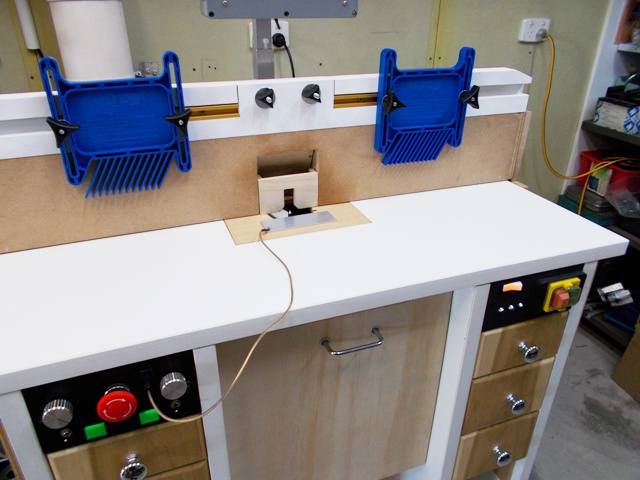
A few more WIP pictures.
Not the greatest photo but the Sensor is the tiny black blob in the lower right hand side of the photo, there is a small aluminium angle rail (Bunnings) just entering the sensor path.
Testing everything with the Router table top off, the fence is totally independent of the Router cabinet top.
 (1) Our small workshop layout __ (2) Bandsaw circle cutting jig __ (3) Spindle sander modifications __ (4) Dust Sensor
(5) Router table redesigned ____ (6) DC and where it all began __ (7) Bandsaw dust extraction build
-
13th August 2018, 05:18 PM #253
Supporting my wife's hobby.
- Join Date
- Nov 2013
- Location
- Caboolture QLD AU
- Posts
- 781
Just found my heavy pedestal drill vice, mounted the dial indicator to it and did a dozen measurements at the centre of the fence.
The Fence "always" returns to within 0.01 mm of the position sensed by the optical sensor and the control software. That's 0.0003 of an inch.
Look again at how far away that sensor is mounted from the centre of the Fence, again, that 0.0003" difference is for the entire system, software + sensor edge detection + bearing slides + screw drives + timber side plates, timber fence and overall cabinet construction. Some may have dismissed this as a folly, especially as my construction used low cost scrap and junk, the purchased parts for this entire system (except the Micro controller) cost less that a typical commercial manual router lift. The Micro controller cost around $160.00 - the software - nothing as I coded it from scratch.(1) Our small workshop layout __ (2) Bandsaw circle cutting jig __ (3) Spindle sander modifications __ (4) Dust Sensor
(5) Router table redesigned ____ (6) DC and where it all began __ (7) Bandsaw dust extraction build
-
14th August 2018, 12:37 PM #254
Supporting my wife's hobby.
- Join Date
- Nov 2013
- Location
- Caboolture QLD AU
- Posts
- 781
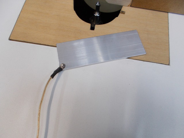
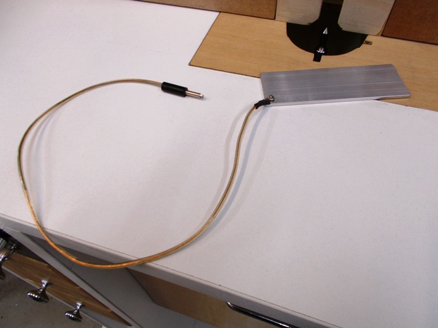
Knocked up a Touch pad for setting the router bit home position, this allows you to refit router bits and always start from exactly the same reference position, any saved Job offsets are always referenced to these Fence and Bit Home positions, so with a touch of an on screen button, the software will automatically set the actual working Fence and Bit positions to exactly the last position as you saved when you last did that job.
FYI you can have multiple fence and bit positions for different parts of the same job, each with a description and job information. Each positions is just a button touch away. I didn't realise how quick and accurate this would turn out to be until I actually used it in testing.
Once the home or zero reference positions are set, you can also use the touch pad to set the router bit height to any position on the cutting surface if desired, the pad is just a piece of aluminium so it can be used on it's edge as well to easily reference any part of the cutting edge or Bit to the table top.
That's the last of the construction and design work done, now to tart it up when I get some spare time.
Single lead for the touch pad plugs into the front of the Manual control panel when needed.
 -
- 
Hard to see but there is a small black socket at the top RH side.
 (1) Our small workshop layout __ (2) Bandsaw circle cutting jig __ (3) Spindle sander modifications __ (4) Dust Sensor
(5) Router table redesigned ____ (6) DC and where it all began __ (7) Bandsaw dust extraction build
-
14th August 2018, 12:43 PM #255
GOLD MEMBER
- Join Date
- Jun 2005
- Location
- Helensburgh
- Posts
- 7,696
Mike, go and have a beer, you deserve it.
CHRIS


 Reply With Quote
Similar Threads
-
Router table - Build or buy?
By Dazm in forum ROUTING FORUMReplies: 9Last Post: 12th November 2015, 11:35 AM -
New router table build - no really!
By snowyskiesau in forum ROUTING FORUMReplies: 24Last Post: 14th November 2013, 08:02 AM -
New router table build
By snowyskiesau in forum ROUTING FORUMReplies: 12Last Post: 27th May 2012, 01:35 PM -
Another router table build.
By Nihilist37 in forum ROUTING FORUMReplies: 2Last Post: 31st May 2009, 07:30 PM -
Want to build a table for router and cms
By Guy in forum HAND TOOLS - POWEREDReplies: 3Last Post: 23rd June 2004, 12:31 AM
