

 Thanks:
  Likes:
  Needs Pictures: 0
 Picture(s) thanks:
Results 16 to 30 of 35
-
1st May 2016, 09:17 PM #16
 .
.


- Join Date
- Feb 2006
- Location
- Perth
- Posts
- 27,791

Very tidy indeed, well done. It looks like a very interesting system, If I were closer I would offer to measure the flow rate.
Have you done any noise measurements?
A couple of comments
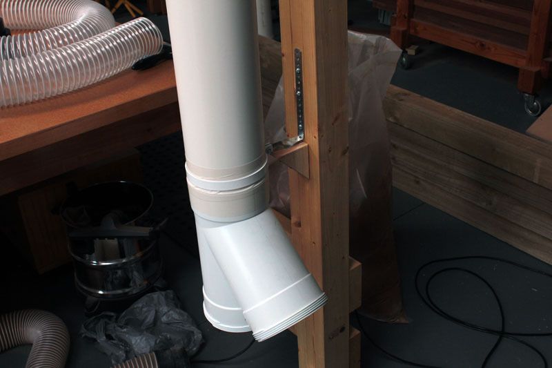
First one is, why did you add an elbow after the outlet? - surely it would be better to vent straight outside at that point. It almost looks like the Blower should be rotated by 90�?
Second is the vent is right next to the door. This means the fine dust will be sucked straight back inside the shed unless you keep the door closed.
You can test your system by weighing out a known amount of representative sawdust and then sucking it up and weigh what comes out in the cyclone.
The important thing is getting a "representative sample of sawdust" - you cannot just use what the cyclone captures as that has already been filtered so it is non representative.
The best thing to use would be the stuff that has been collected by a DC with either a PF or Needlefelt bags.
The needle felt bags need to be shaken or the PFs need to be cleaned so the fine dust they have captured falls down into the collector bags.
A more stringent or definitive test would be to only use the dust generated by someone who has been sanding with a drum or belt sander.
A suitable substitute would be a 1kg bag of flour.
-
1st May 2016 09:17 PM # ADSGoogle Adsense Advertisement
- Join Date
- Always
- Location
- Advertising world
- Posts
- Many
-
2nd May 2016, 10:11 AM #17
Intermediate Member
- Join Date
- Sep 2008
- Location
- melbourne, australia
- Posts
- 32
Yep, there is a very good reason for that....................... I didn't think of it. Originally Posted by BobL


This is OK because it does another ninety degree turn and ends up out the back. There is a small storage area in between the old workshop and the new shed. Originally Posted by BobL
I did originally plan to put the cyclone out there but various problems cropped up that prevented that from happening.
-
2nd May 2016, 05:01 PM #18
Senior Member
- Join Date
- Oct 2012
- Location
- Mango Hill, Moreton Bay Region
- Posts
- 204
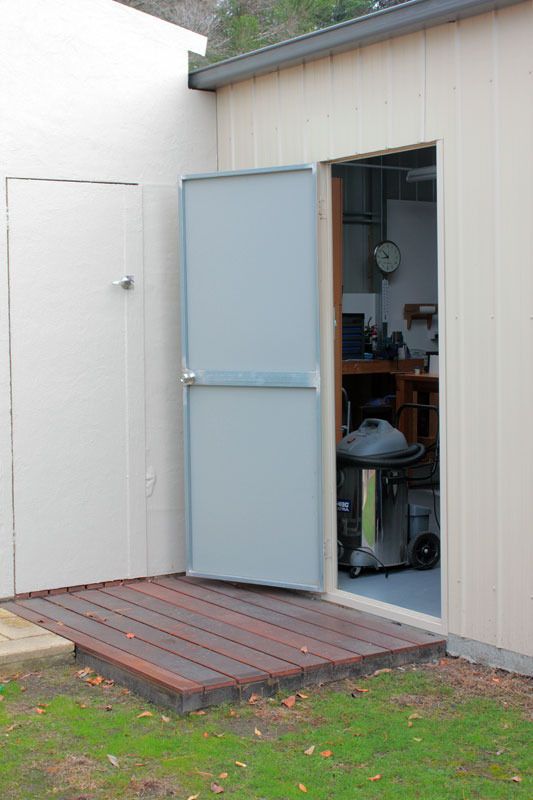
All you have to do now is stop all that dirty air from outside, coming in to the shed
 . its good to see another person going down the road of the Cyclone dust extractor. keep up the great work and photos
-
3rd May 2016, 02:52 PM #19
Member
- Join Date
- May 2007
- Location
- Auckland, New Zealand
- Posts
- 51
Nice cyclone build.
If you want to make some flow measurements you could do this indirectly by knocking up simple manometer to measure static pressure and reading off air flow from the attached fan curve. The fan I used for producing this is a similar looking Carbatec 2HP unit so you should be able to get some reasonably applicable data.
For a manometer, all that is needed is to screw a hose barb fitting flush with the inside wall of a straight section of ducting and connect to 6mm clear tubing with some coloured water inside. The other picture shows my manometer setup used on some recent testing. (please ignore intentional 'mistake' with this fan/cyclone setup)
fancurve.jpgIMG_0145.jpg
-
8th May 2016, 11:21 PM #20
Intermediate Member
- Join Date
- Sep 2008
- Location
- melbourne, australia
- Posts
- 32
Thanks Opelblues.

Thanks for the tip Muchacho, looks like a neat cyclone you have there. Have you posted a thread about it here?
I managed to lay out the tubing and here are some pics to show how it works. Very basic as it's just making the dust collection point in the center of the shed where most of the work gets done.
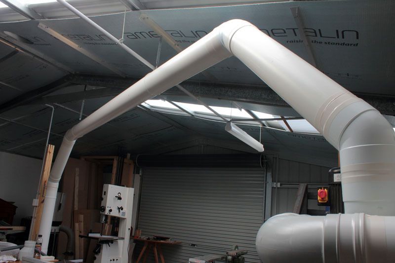
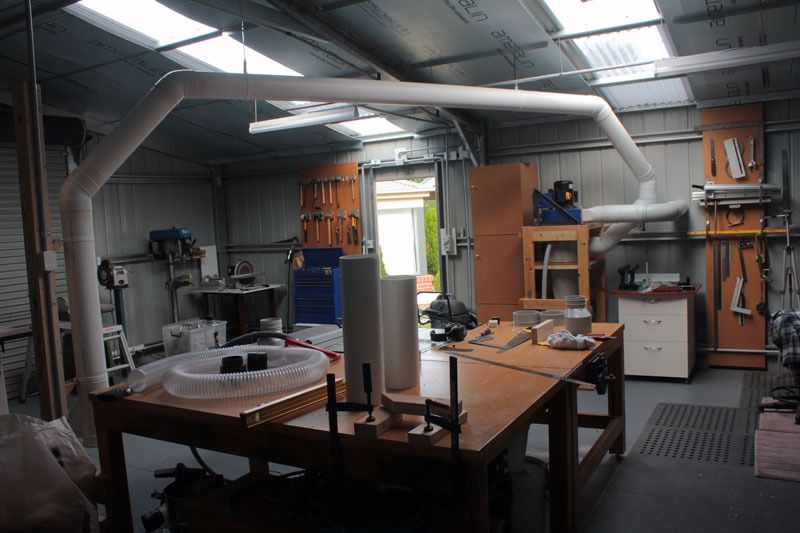
It terminates in a 'y' to have two full time lines.
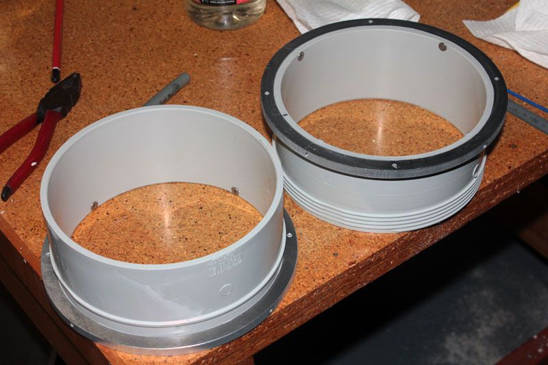
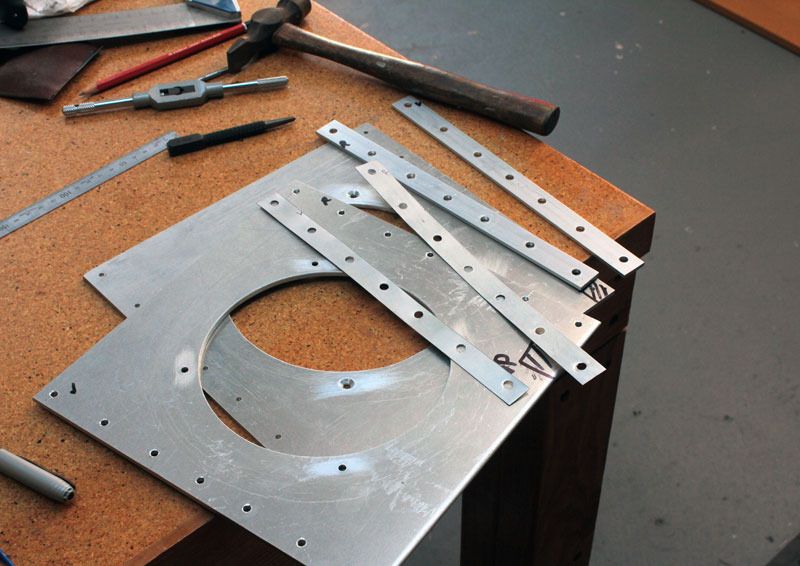
A couple of blast gates need to be installed at this 'y' junction. I watched a bunch of you tube videos to see how other DIYers have made their own and also took a look at the various commercial offerings around. The principal is very simple and virtually all the examples I looked at worked in a similar way. So all that is needed is a sliding door and a pair of tubes, one male and the other female. The web was searched thoroughly to find some flanges that could be bolted straight on to the body of the gate I will make, and this only yielded a female version and this cost over thirty two bucks. So if a male version could also be found, then the total, just for the tubes would run me over 120 bucks, ouch. Obviously I will make my own as there is still plenty of aluminum laying around from a previous life.
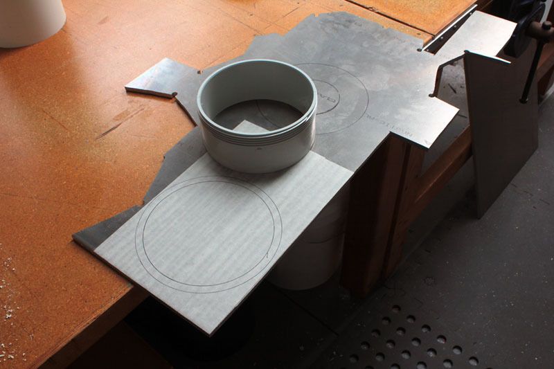
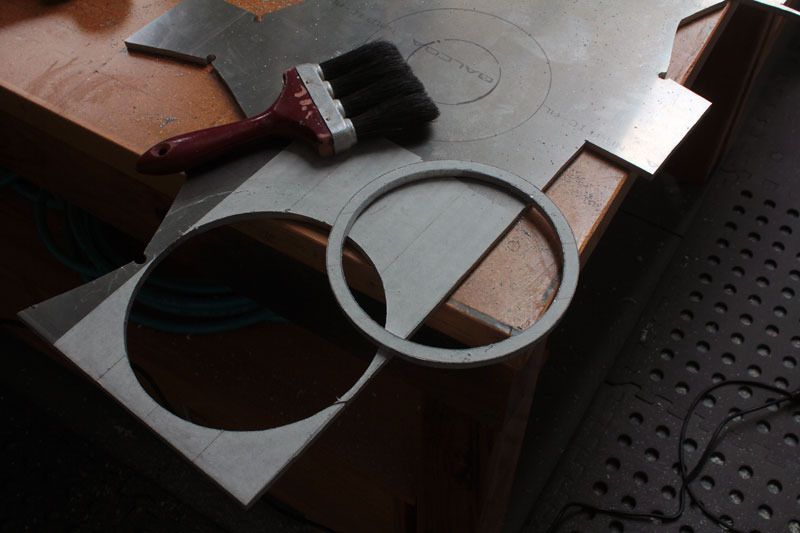
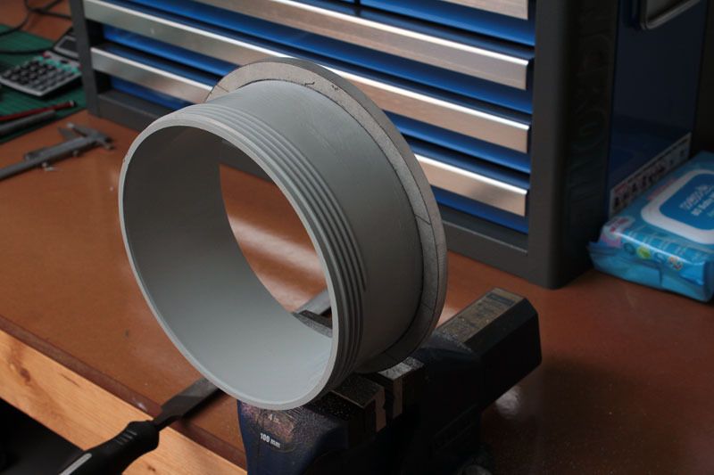
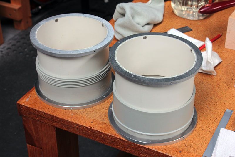
First some flanges need to be made up, four in total, two males and two females. Here the female tubes are made from an adapter that is cut in half on the table saw, and some aluminum collars cut from 8mm plate.
Finishing the outside is easy on the disc sander but the inside needs to be done with a half round file.
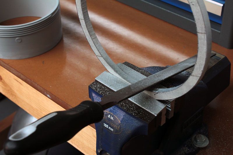
And it's filed till the tube fits nice and tight.
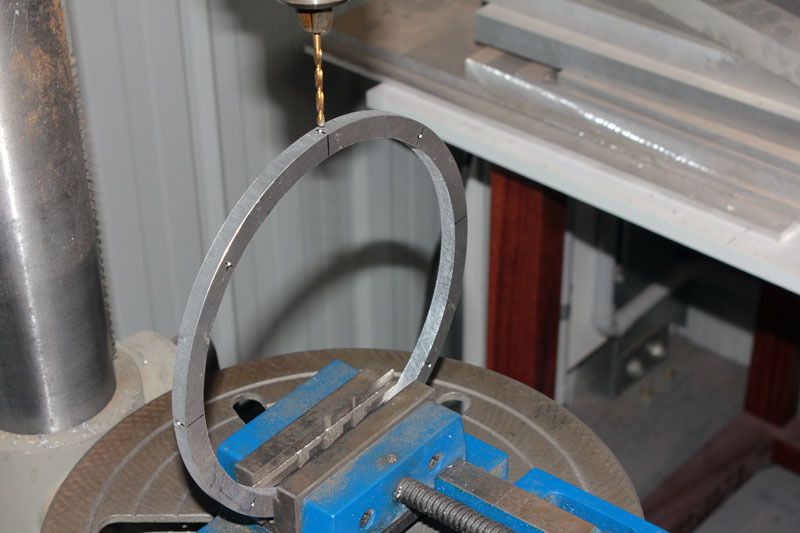
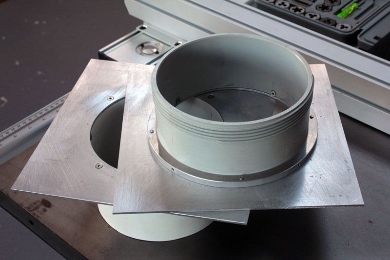
Drilled and tapped.
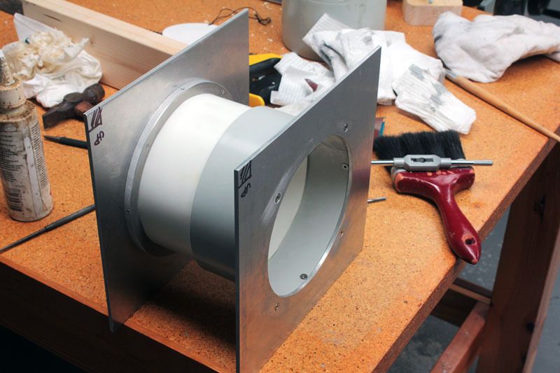
An adhesive and sealing compound is smeared around the inside edge of the collar and m4 screws used to fix the two parts together.
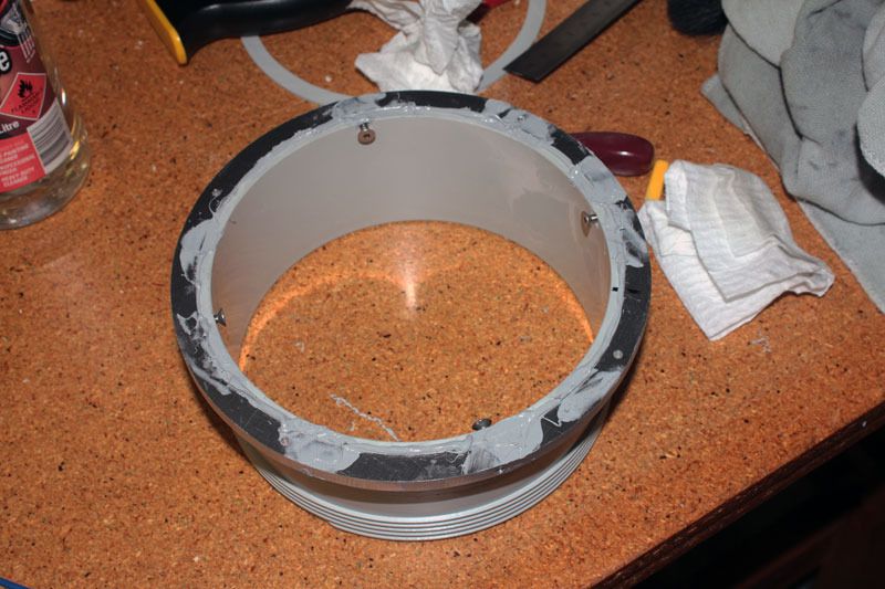
Cleaned up with some turps.
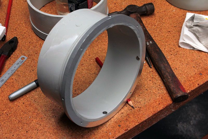
And so far the two female tubes are done.
Back when there is more to show.
-
9th May 2016, 07:33 PM #21
Member
- Join Date
- May 2007
- Location
- Auckland, New Zealand
- Posts
- 51
Hi Newby, Originally Posted by oldnewby
I've posted a couple of threads. The first one is about the prototype here which includes the testing for the fan curve attached above, andhere is the post on the mark II version which I produce for sale. (If these hyperlinks don't work you should be able to find them by searching my posts).
-
9th May 2016, 09:14 PM #22
.
- Join Date
- Feb 2006
- Location
- Perth
- Posts
- 27,791
150 mm female flanges (see below) are available for about $7, however 2 would be needed for each gate which is still expensive considering a 150 mm gate from Cleave costs $34.
Flange.jpg
A coupler costs $7 which can be split in half and I just PVC glued mine direct to a square piece of 3mm PVC that forms one side of the gate.
I turned the hole using a lathe so I could get a real tight fit.
Housingturningtest.jpg
5 years on and the PVC glue is holding well.
My 3mm PVC gates are however too flimsy and can be easily bent.
I will replace these with some 3mm Al WIGRTI.
I would direct you to my post on this but the pics have gone for some reason.
-
16th May 2016, 02:37 PM #23
Intermediate Member
- Join Date
- Sep 2008
- Location
- melbourne, australia
- Posts
- 32
Thanks Muchacho, very interesting work on that cyclone.

Thanks BobL.
Almost managed to complete the blast gates last week end.
Two sets of in/out flanged tubes.
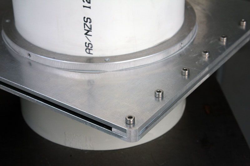
The main bodies are made from 4mm sheet, fitted via M4 screws from the inside. Care has to be taken here to ensure the countersunk screws are well below the surface so the slides can move freely.
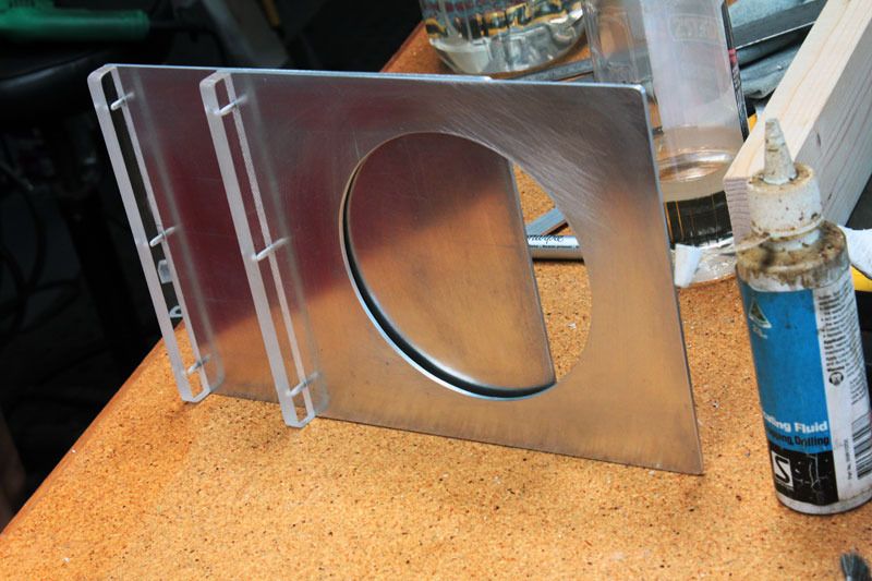
The slides will be made from 3mm sheet so the two halves of the body are joined together via a pair of 3mm spacers and a couple of 0.6mm shims.

Here are the parts. The main plates plus spacers and shims.
A bunch of M4 screws hold the lot together.
When first planning the slides, the original idea was to make a slide for each gate. The slide would have open and closed positions on the one piece.
This would have made each slide over 400mm long. Apart from the waste of material, this idea wasn't going to float because of the amount of space needed for operation.
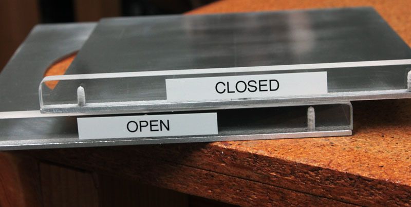
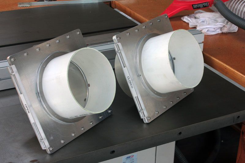
So, instead, a pair of slides were made, one open and the other closed. In use one simply swaps em around depending on which outlet is to be used.
A piece of 10mm acrylic is used as a stop/handle.
I asked my daughter to make some labels on the machine she uses to label her school books.
Corners are rounded off on the disc sander.
Almost finished pair of gates.
Just getting a look at how they work together. I think the 'Y' will need to be lifted up a bit.
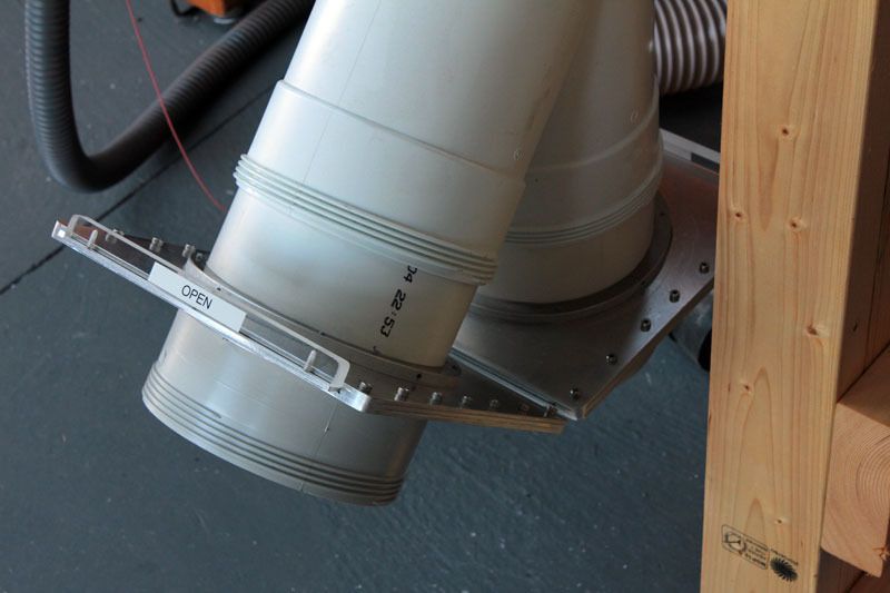
Next week end some magnets will be added to keep the slides in place and maybe a test run to see how it works.
-
16th May 2016, 03:48 PM #24
.
- Join Date
- Feb 2006
- Location
- Perth
- Posts
- 27,791
Great fab work.
I think you need a few more screws along each side of the gates ;-)
I used 3 screws and some silastic down each side on mine.
I reckon you will get sick of removing and inserting separate gates.
When I'm working swapping gates is a walk around the room and its whack/whack/whack and I'm ready to go. To have to stop and thread each new gate would be a real nuisance.
Most of my gates are attached to Y's and it's easy enough to extend the short piece of connection ducting between the gates and the Y's to accomodate the full length of the gates.
I'm in the middle of doing a couple at the moment so I'll takes some pics when I have enough to show.
-
21st May 2016, 05:27 PM #25
Intermediate Member
- Join Date
- Sep 2008
- Location
- melbourne, australia
- Posts
- 32
At the moment only the two outlets will be used so no problem swapping em around. Originally Posted by BobL
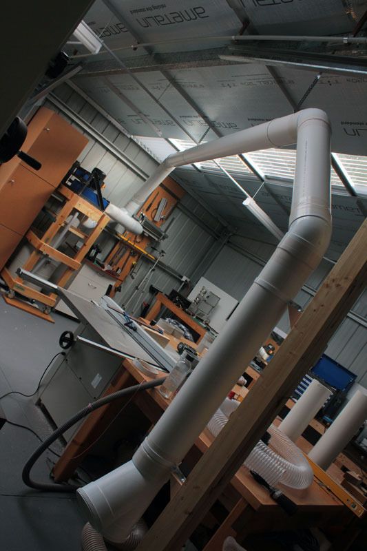
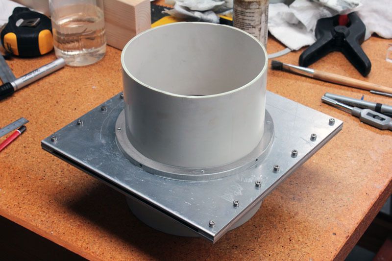
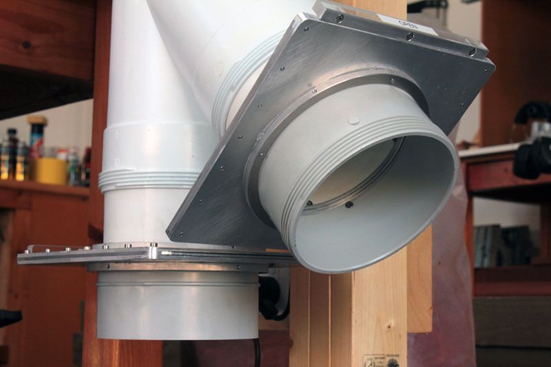
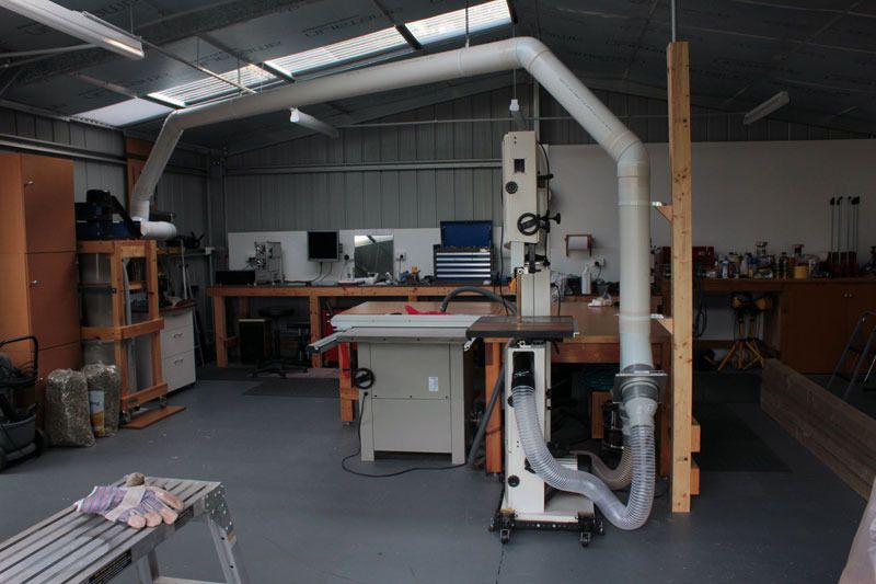
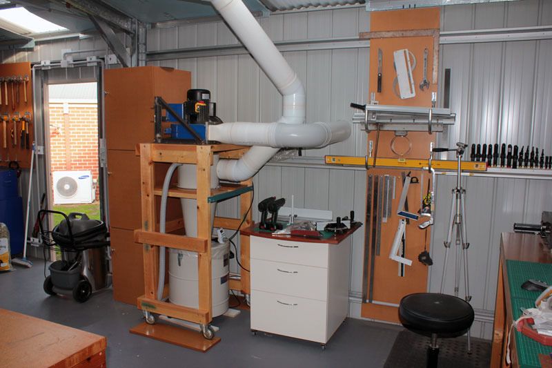
Finished the layout today.
The blast gates and 100mm reducers were fitted to the 'Y' adapter with the help of some PVC duct tape. This lot has a bit of weight.
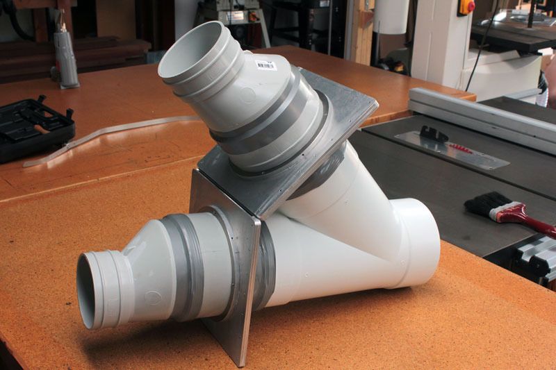
Then the hoses were trimmed and fitted. This will be the full time configuration for the moment. When planing is required, then the hose to the bandsaw will be used.
So that's it for now. In the future it will be easy to extend this system to pick up other tools, the drop saw for instance.
Tomorrow I'll wheel over the thickenesser and give the system a try. I'm using this tool first because it generates the most waste and in the past, using a standard extractor, the hose has blocked up several times.
-
21st May 2016, 08:21 PM #26
.
- Join Date
- Feb 2006
- Location
- Perth
- Posts
- 27,791
It's such a pity you installed 6" all the way to the BS with beautiful big 6" gates and then attached it to the BS via 1 piece of 4" flexy???
I take it the other 4" flexy is going to the TS?
If so, I doubt there will be more than 200 cfm through the BS flexy, and maybe 350 CFM through the TS flexy and the blade guard
This is not enough to grab the fine dust at the source of production.
The whole idea of using 6" is so that either 6" ducting can be connected to a machine like a table saw, or 3 x 100 mm of ducting can be connected to a machine like a BS.
It's not just the flexies but the ports on the machines and the machines themseives have to be opened up to get air into the machines so that air can then get out of machines.
I realize folks don't like cutting holes in machinery but that is the only way to do it. Maybe you plan to some of this in the future? - I just don't want newbies to think this solves the woodiest problem.
What you have done is akin to using a V8 engine with the carby from a Mini.
-
23rd May 2016, 12:43 AM #27
Intermediate Member
- Join Date
- Sep 2008
- Location
- melbourne, australia
- Posts
- 32
I tried out the system today. First with the thickenesser, as this machine generates the most waste and it would be difficult to run it without an extractor.
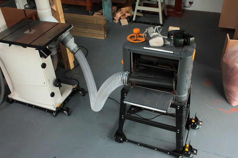
The chips were cleaned away and no dust was left in the hose. After a few passes a small amount of dust and chips was left on the bed and the floor.
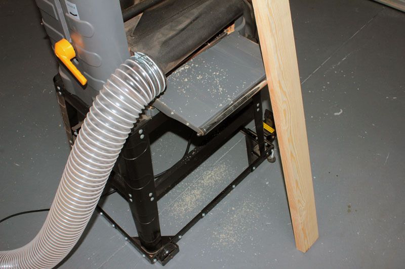
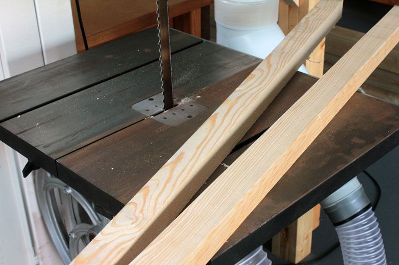
Next up a piece of pine was cut on the bandsaw.
Again the cyclone worked well. Only a small amount of dust around the blade.
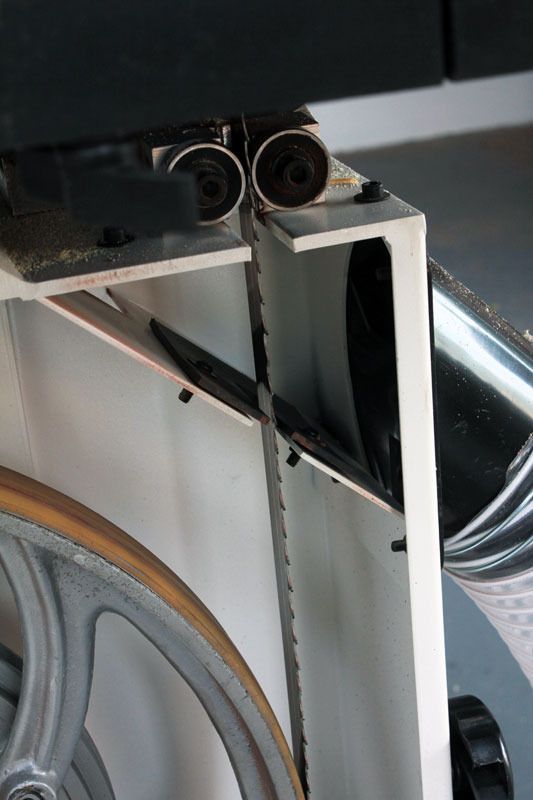
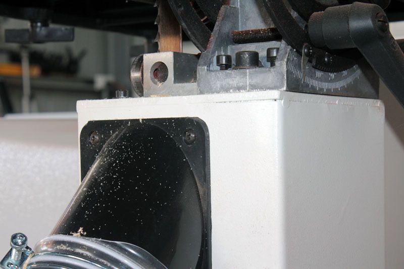
And nothing in the hose.
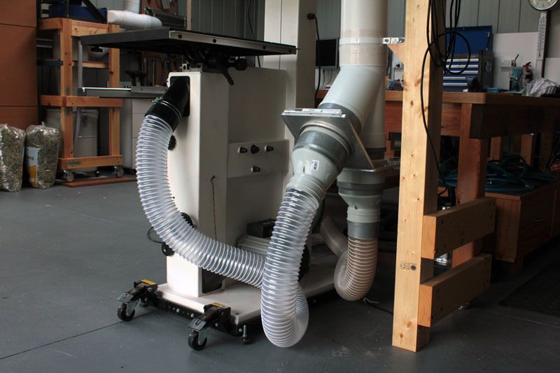
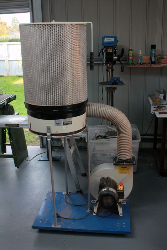
In my (subjective) opinion the new set up performed better than my old set up below.
I'm happy with the new system as it stands. It works well, doesn't leak and is easy to use. The table saw was not run because I already know that the internal design of the dust collection solution is very poor. Whenever the saw was used, a great deal of waste was left under the machine. In a few weeks the next step in the build will be to rebuild the internals of the table saw and run 150mm all the way, also a new blade guard will be made, covering a larger area with a larger diameter hose. I don't think this will be too difficult. Also the tube will eventually be extended to the other wall where the dropsaw station is located. but these jobs are beyond what I started this thread for.

Final thoughts.
I originally started this thread after stumbling upon a thread by scuzyboy. Because I had just started building my system I thought some of the readers that own, or are considering purchasing one of these little cyclones, may be interested in seeing what can be done with one. I hope what I've done can be of some help. For those on a tight budget these little 2/3 cyclones paired with a cheap blower can be a very useful addition to a work space. The budget was somewhat blown from earlier estimates and ended up at between 700 to 800 bucks. But the extra was mainly the cost of PVC pipes and fittings, they are not cheap. However, the cost of just the cyclone itself, that is blower, frame etc came in at under 500.
I should point out that I've never made the claim that this solution is suitable for working with machinery without breathing protection. I always wear a mask when operating any of my machines (I wear a mask even when hand sanding), and even after the machining has been completed and the doors opened up, I still keep the mask on for a good hour or so. I have dust extraction to keep the level of dust down to a minimum within the bounds of what I can afford and can live with.
-
23rd May 2016, 12:57 AM #28
.
- Join Date
- Feb 2006
- Location
- Perth
- Posts
- 27,791
Originally Posted by oldnewby
-
23rd May 2016, 01:10 AM #29
.
- Join Date
- Feb 2006
- Location
- Perth
- Posts
- 27,791
Tip, the throat plate slot works better if it is behind rather than in front of the the teeth. Someone on the forum told me about this and I found it made a big difference. Then I looked at a bunch of BS photos on the web and noticed that all the high end BS had their slot this way. Originally Posted by oldnewby
Its weird how one side of your table looks rusty which the other side looks pretty clean?
Is there a reason for this?
-
3rd December 2016, 04:59 PM #30
Supporting my wife's hobby.
- Join Date
- Nov 2013
- Location
- Caboolture QLD AU
- Posts
- 781
Hi, wondering how you are finding your 2/3 unit after a few months of use? I had a chance to get an unused unit that is a few years old for $140 and intend to do some testing to see just how much loss it introduces.
1. I know the loss figures being quoted for this type of compromised size and design.
2. I cannot afford a full size cyclone at this time - and don't try the how important is my health card - I take other precautions.
3. This will cost me NOTHING but my time to test OR modify.
I have been monitoring my current 3HP system with a permanent current meter and manometer to watch the continuing decline with dirty filter bags, or more likely what is called - seasoned bags. The current and vacuum difference for each DC port and pickup has been logged from the new installation over the past 3 year, so I have some rudimentary figures to compare.
NOTE: Yes - I understand the limitations of using current and vacuum as an indication of actual flow rates or system performance AND the incorrect assumptions that can be made - I have learned a lot over the past few years - AND despite this, yes I AM going to try this small cyclone.
Sooooooo back to the unit - fortunately this thing is relatively easy to modify including a better intake and ramp, however I plan to try it unmodified to start with. One thing I have noticed is this ridiculous equalizing hose and tube through the intake path into the exit tube - someone must have had a brain fade when they did this, any way, it's simple enough to remove and also eliminate the need for same.

 Reply With Quote


Similar Threads
-
Cyclone
By fozzy767 in forum WOODWORK - GENERALReplies: 8Last Post: 8th October 2014, 07:07 PM -
WIP Cyclone
By Al B in forum METALWORK FORUMReplies: 147Last Post: 4th August 2008, 11:52 PM -
Cyclone mod. Not quite right.
By minvec in forum TRITON / GMCReplies: 8Last Post: 21st January 2007, 09:15 PM -
Fan for Cyclone
By Chris Parks in forum DUST EXTRACTIONReplies: 13Last Post: 14th February 2006, 01:41 PM -
Making cone for Cyclone
By inferno6688 in forum DUST EXTRACTIONReplies: 10Last Post: 11th January 2006, 11:28 PM
