

 Thanks:
  Likes:
  Needs Pictures: 0
 Picture(s) thanks:
Results 1 to 15 of 35
-
20th April 2016, 01:17 PM #1
 Intermediate Member


- Join Date
- Sep 2008
- Location
- melbourne, australia
- Posts
- 32
 2/3 cyclone. Making the best of it.
Like many wood workers I have always wanted a good dust extraction solution for my work space. I did some research a few years back and everything pointed to utilizing a cyclone system and venting the output to the air outside without filtering (I am able to do this because there are no dwellings behind my shed).
Of course I saw and lusted after the Clearview solution, but I don't or am unlikely to have four grand to spend on a dust extractor. So I looked around for a cheaper (much cheaper) solution.
I found a little cyclone unit for sale at Hare and Forbes. It was basically just the cyclone and waste bin from the full system that they sell for about fifteen hundred bucks. This cyclone cost about two fifty at the time so I bought one. The next thing I thought about was to get a motor/blower assembly to put on top. After searching the popular for sale site for a few weeks, just what I was after showed up, someone had thrown all the other bits of a Carba-tec 2hp dusty away and offered the motor/blower for a hundred bucks, so I bought that as well. That was about two years ago and these parts have been sitting around gathering dust.
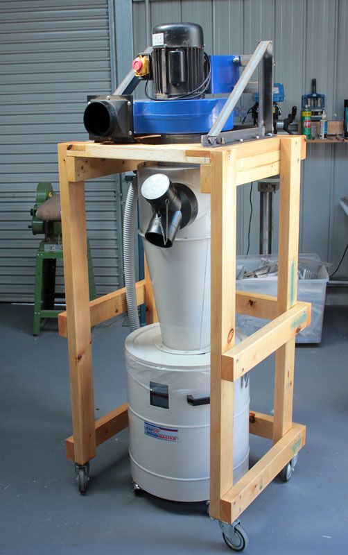
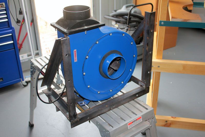
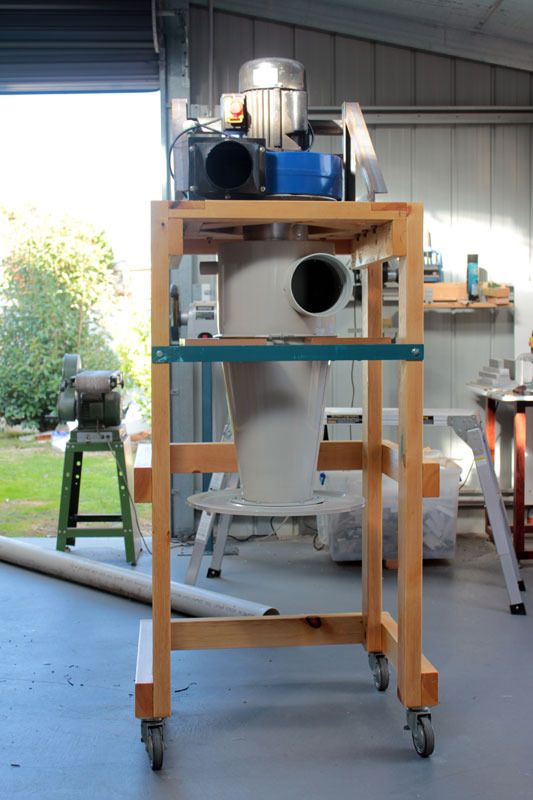
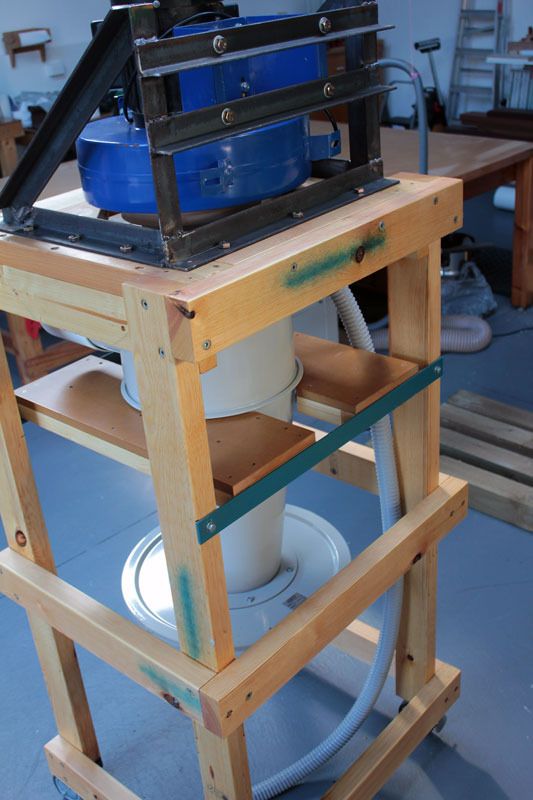
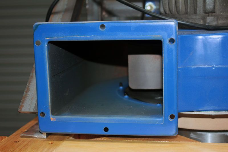
Then just a few weeks ago I decided to dig these parts out and attempt to make something functional. The first thing was to build a frame so the blower could sit on top of the cyclone...................but hang on a minute, before I go on, after the frame was made and the blower was mated to the cyclone, a wood work forum update appeared in my email, so I ended up reading some of the articles here in the dust section and decided to go back and open up the cyclone and blower to the max so they could accept 150mm ducting. I noticed that there is another thread here about this 2/3 cyclone so have decided to post my work here. I should make a few points though., I am not expecting performance anywhere near that of say a CV system nor have I taken a great deal of trouble to make any of the parts 'pretty', I'm just aiming to make a functional piece of kit for less than five hundred bucks including the ducting. So here's what I'm up to............................................
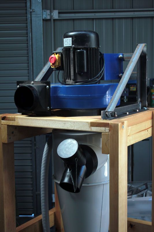
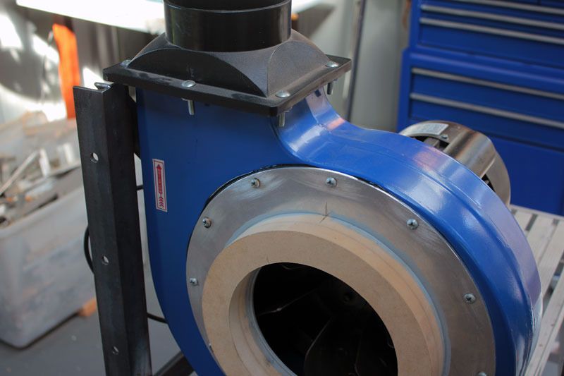
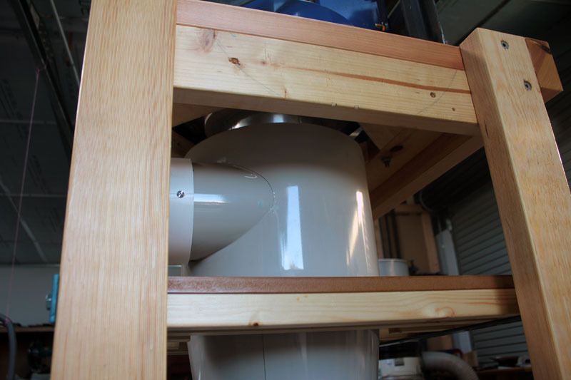
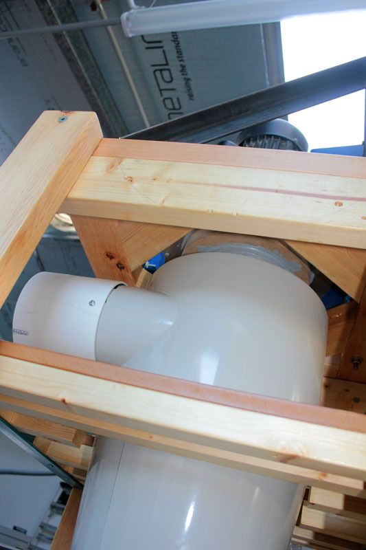
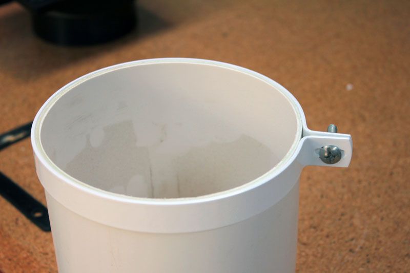
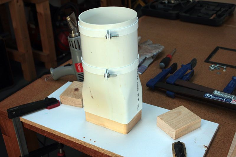
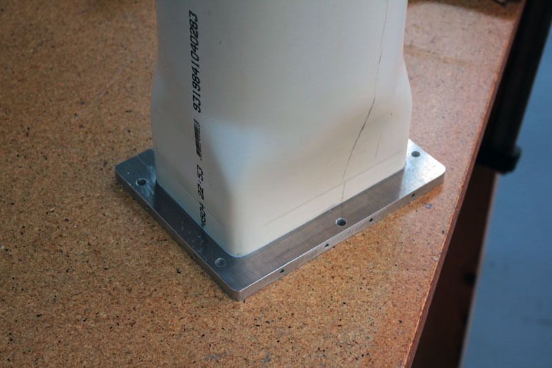
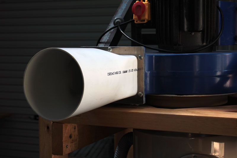
This is were I was up to before work was started on opening up the blower and cyclone. Here a frame was made up from 5mm angle so the motor/blower could be suspended from the back. The trolley is made from cheap MGP10 pine and the swivel casters have been sitting around for twenty years or so. The blower is fitted to the cyclone through an opening that is 120mm or so in diameter. A reducer is used on the cyclone output.
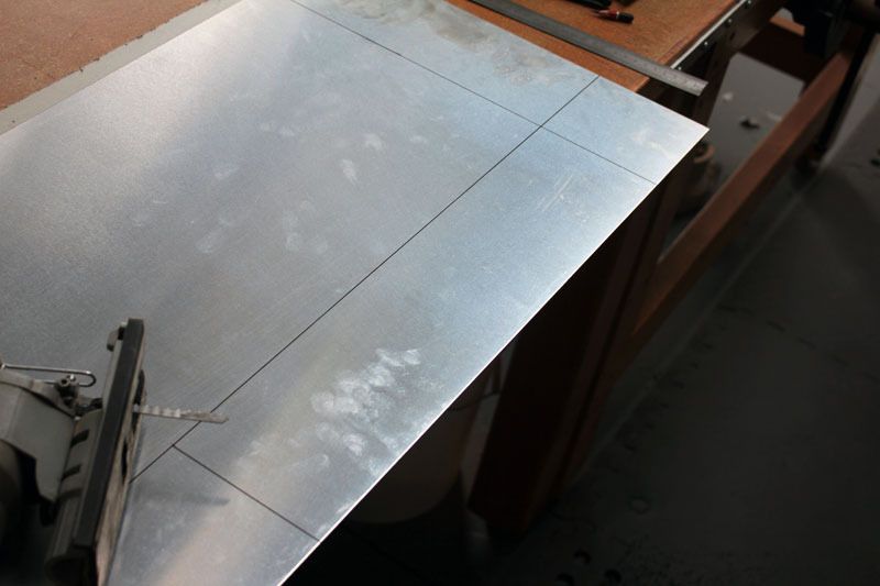
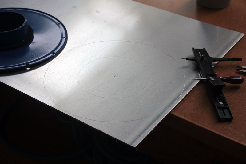
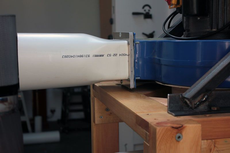
Because the distance between the cyclone and blower was determined by the adapter/reducer on the cyclone, once this part is discarded so that the full opening can be used, this distance (110mm) needs to be covered with a tube that is 176mm in diameter (the size of the output from the cyclone).
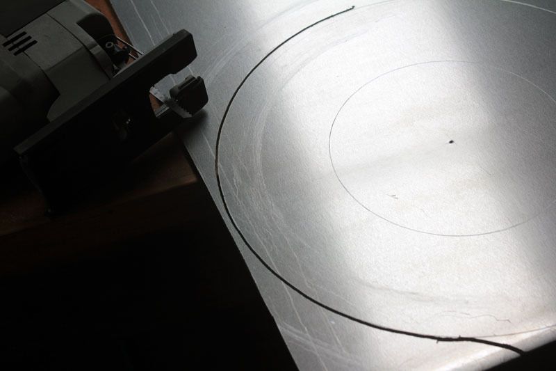
I couldn't find anything at this diameter so had to make a tube myself. First some 2mm aluminum is cut from a sheet. A jigsaw is used for this.
After the rough edges are filed down my little bending rolls are put in the bench vice and this piece of 2mm sheet is made into a tube.
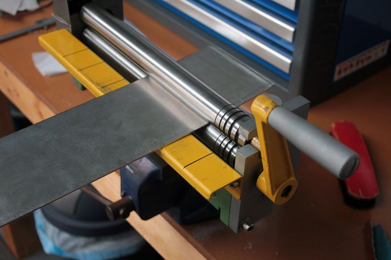
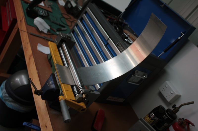
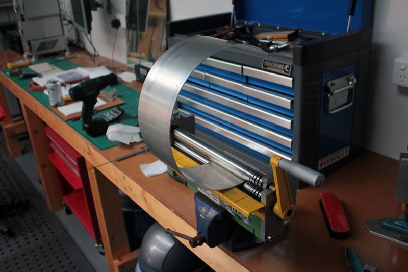
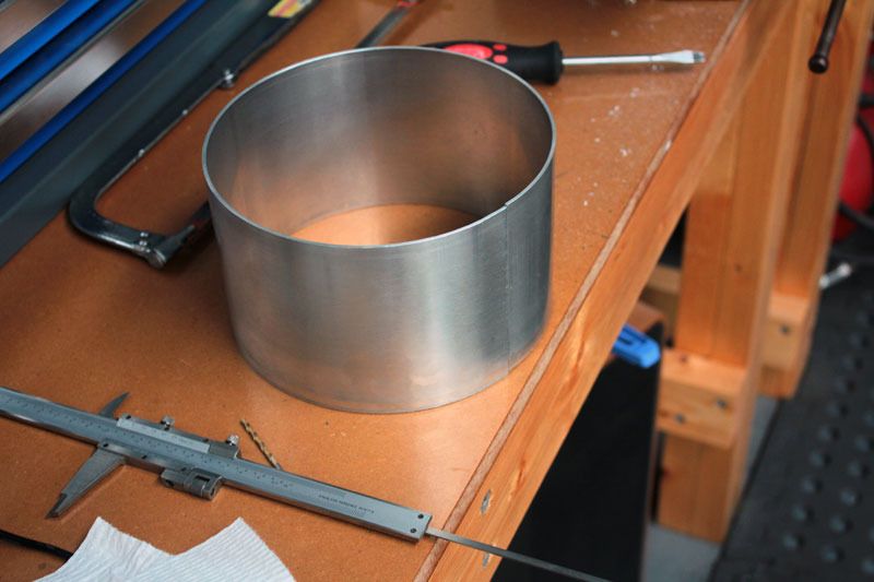
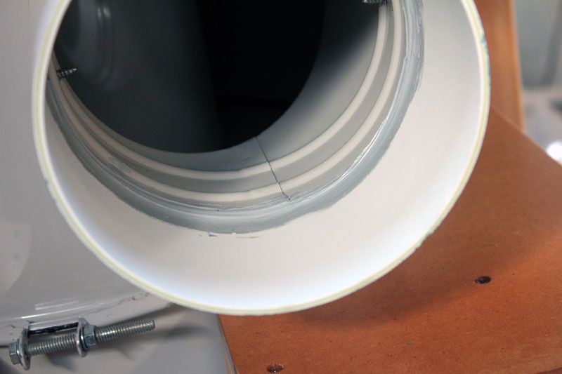
Because the edges of this tube fit so well it can be riveted to the cyclone and caulked up on the inside and out. The rivets are fixed from the inside so the compressed part that sticks out the most is on the outside.
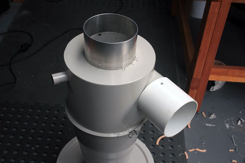
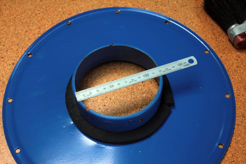
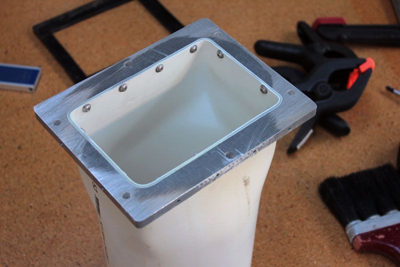
The next job is to open up the input to the blower. To do this a new plate needs to be made. Here, a new plate is made from some 4mm sheet.
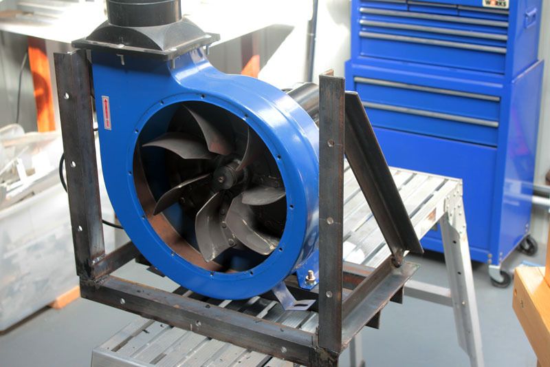
And a sleeve from two pieces of mdf. This would be much easier with a lathe. The sleeve is fitted to the plate with screws and sealing compound.
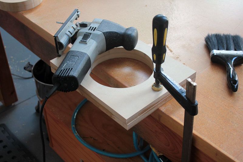

The original rubber seal is discarded and silicon gasket used to seal this area.
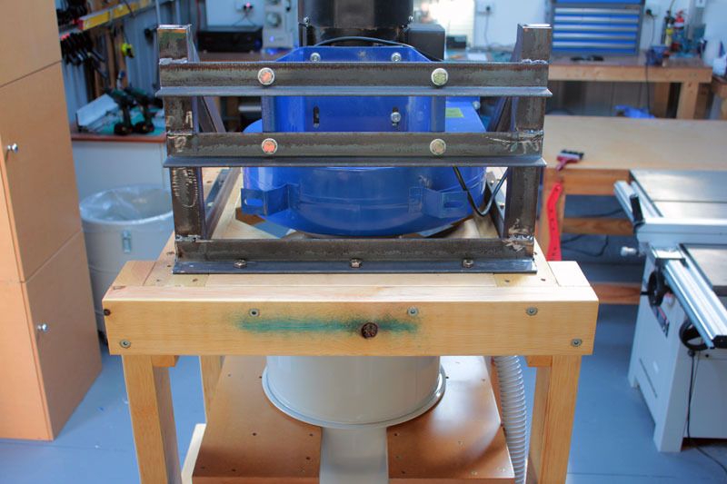
And then all is fitted back into the trolley.
And that's all for the moment. I've bought a cheap power meter to check current draw so once some ducting is hooked up I can see how well this set up performs.
Back soon.
Cheers
Attila
-
20th April 2016 01:17 PM # ADSGoogle Adsense Advertisement
- Join Date
- Always
- Location
- Advertising world
- Posts
- Many
-
20th April 2016, 05:17 PM #2
SENIOR MEMBER
- Join Date
- Jul 2013
- Location
- Lower Blue Mountains
- Posts
- 132
Great work I just bought this unit to and it works great. I completely cleaned my DE washed the bags to see how much fine dust got through and to my surprise none. I will keep an eye on this as this is what I will be doing to once I get time. The 6" is the trick [emoji6]
Acoustic and Electric guitars and Basses.
-
20th April 2016, 05:50 PM #3
.
- Join Date
- Feb 2006
- Location
- Perth
- Posts
- 27,793
Looks like some nice fabrication work there!
It doesn't look like the cyclone inlet is a true 6" inlet if you can get a piece of 150 mm ducting over it?
If so this will be the limiting factor to flow.
The impeller outlet will also need to be opened up by removing that plastic rectangle to round reducer other wise it will act as a throttle point.
I am a little concerned at the extent you opened up the blower as this may affect the dust separation performance.
To a cyclone be effective at separating the dust the blower has to draw its air from the very middle of the cyclone - extending the collection further out may lead to problems.
In practice is need be no bigger than the biggest ducting in use so it does not need to be any bigger than 150 mm which I think that is what it already was.
The other improvement that could be made is to bell mouth (radius) the inside of the entry into the impeller - have a look at the generic 2HP DC sticky to see what I mean.
This reduces turbulence significantly in the case of the 2HP DC
However because you have already opened the connection up so much it may make things worse.
A narrower but "slippery" connection usually works better than a wider shape edged connection.
That cyclone is a pretty old design - the non angled entry will not have a very effective dust separation and increases the back pressure. The impact on a 2HP DC which is already a limited pressure generator can be very significant. BP found that these cyclones created up to 4.5" of back pressure. Given that a 2HP DC can only generate about 8.5" of static pressure this only leaves 4" of working pressure. Opening up the impeller does not change the pressure that much as this is determined by the RPM, and the things like the shape of the impeller housing and blades.
Anyway lets see how it goes.
-
20th April 2016, 09:11 PM #4
Senior Member
- Join Date
- Oct 2012
- Location
- Mango Hill, Moreton Bay Region
- Posts
- 204
I like what you have done, with limited funds you have to do with what you have. it might not be a 1000cmf unit but at the end of the day it works for you. and that better than none. once again great work
-
21st April 2016, 12:44 AM #5
Intermediate Member
- Join Date
- Sep 2008
- Location
- melbourne, australia
- Posts
- 32
Thanks for the replies.

I did forget to mention that the next task is to rebuild the output of the blower so it can connect to 150mm pipe.
The outlet from the cyclone is 175mm in diameter and an adapter is supplied to fit 100mm hose. So I'm guessing the unit is designed to function optimally (for this unit that is) with this 175mm outlet.
As I said above, I'm not expecting this to be the best thing around but I am hoping it will be useful.
-
21st April 2016, 01:03 AM #6
.
- Join Date
- Feb 2006
- Location
- Perth
- Posts
- 27,793
Shouldn't the output of the blower be connected to a fine filter or be directed outside? Originally Posted by oldnewby

Given it is rectangular exit, depending on how far you need to run it and it is not critical you could leave it as rectangular (MDF).
Don't you mean the INPUT to the cyclone?The outlet from the cyclone is 175mm in diameter and an adapter is supplied to fit 100mm hose. So I'm guessing the unit is designed to function optimally (for this unit that is) with this 175mm outlet.
The fact that it is 175 mm does not mean much especially about optimisation. These units are rarely built with any sort of optimisation in mind.
175 mm is an awkward size. There is no cheap ducting available in this size and junctions are impossible to find.
Something to bear in mind is that for any duct to be viable it has to nominally carry air at ~4000 fpm.
For a 150 mm duct this translate stop 785 CFM. If your setup cannot produce this sawdust may fall out of suspension inside the duct and it may even partially clog the duct and further restrict the flow.
The 4000 fpm is a nominal figure by BP and is the standard used by industry I have had no problems with speeds as low as 3000 fpm for short runs of ducting.
-
21st April 2016, 01:04 PM #7
Member
- Join Date
- Jul 2015
- Location
- New Zealand
- Posts
- 69
Nice work. I'll be watching with anticipation to see how it works out for you. I have a 3hp unit and I'm currently deliberating between doing something similar to what you have done vs something like this:
Beginner attempt at DC - thanks to forum members
A question for you, or anyone else: is it an issue to mount the blower on it's side?
-
21st April 2016, 01:39 PM #8
.
- Join Date
- Feb 2006
- Location
- Perth
- Posts
- 27,793
No but you can't mount the cyclone on its side. Originally Posted by WoodyNZ
If you are thinking of mounting the blower on its side and running a connection to the cyclone it usually does not work very well as locating the blower directly to the cyclone.
Adding a cyclone to any DC reduces the available pressure for moving air but the higher pressures available for the larger/more powerful units are less of a hit to the pressure generation leaving enough pressure to move enough air.
This is one reason why the Clearvue uses such a big motor and impeller.
-
22nd April 2016, 06:35 AM #9
Member
- Join Date
- Jul 2015
- Location
- New Zealand
- Posts
- 69
Thanks BobL. What I actually meant was that units like the DC3 or DC7 were intended to be used with the blower mounted in the vertical plane. Are there any issues with doing what oldnewby has done here and mounting the blower to spin in the horizontal plane instead? Lot's of people have done similar things so presumably if it was an issue people would have noticed problems already.
-
22nd April 2016, 09:10 AM #10
.
- Join Date
- Feb 2006
- Location
- Perth
- Posts
- 27,793
Should be no problem. Originally Posted by WoodyNZ
-
22nd April 2016, 04:56 PM #11
Senior Member
- Join Date
- Oct 2012
- Location
- Mango Hill, Moreton Bay Region
- Posts
- 204
do you mean like this

-
23rd April 2016, 08:11 AM #12
Member
- Join Date
- Jul 2015
- Location
- New Zealand
- Posts
- 69
No I didn't actually but that's an interesting option too.
-
27th April 2016, 01:03 PM #13
Intermediate Member
- Join Date
- Sep 2008
- Location
- melbourne, australia
- Posts
- 32
It's a couple of mm smaller than the inside measurement of the tube which is greater than 150mm. I haven't used inches for a long time and don't know why this matters. It's very close. Originally Posted by BobL;
Yep, I spoke of this in the first sentence of the OP. Originally Posted by BobL
No. Originally Posted by BobL;
No, it was less than 120mm. Originally Posted by BobL;
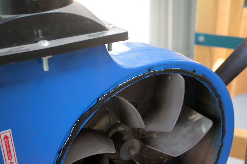
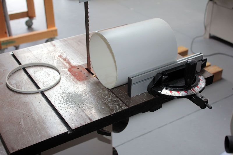
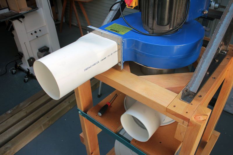
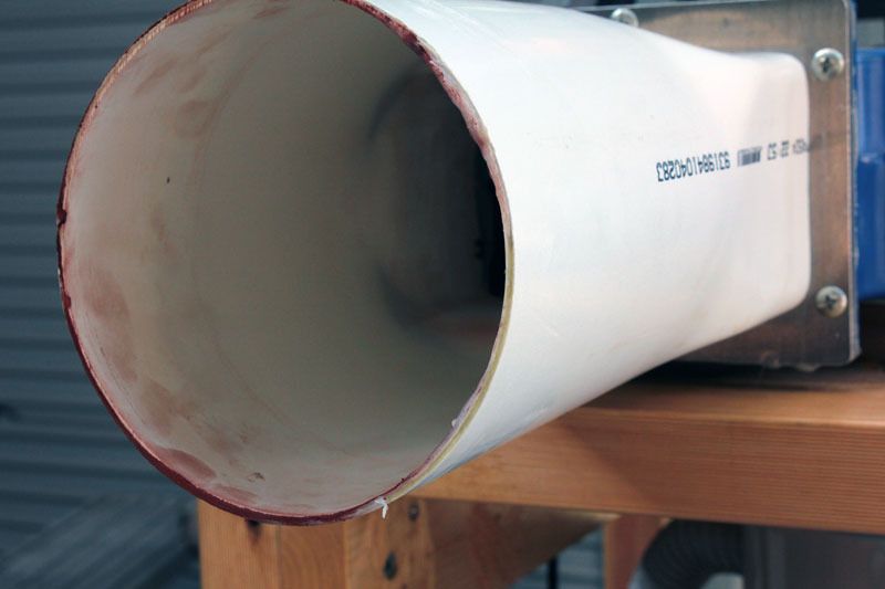
So I had a few spare hours over the weekend and decided to have a go at making the output connection from the blower.
This will be a transition from the square opening to a 150mm tube. I'm doing this instead of just building a square outlet for the flexibility it will offer, there are three possible locations for the completed cyclone and being able to just connect to standard tube will make things easy peasy.
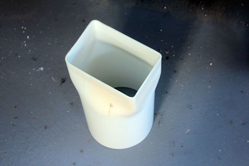
This is the outlet from the blower.
A first attempt was to use a short piece of tube.
I used a heat gun to soften the PVC and tried to form a square on one end with some wood cut to the size of the blower opening.
As you can see here it was less than ideal.
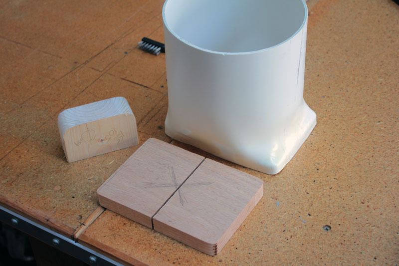
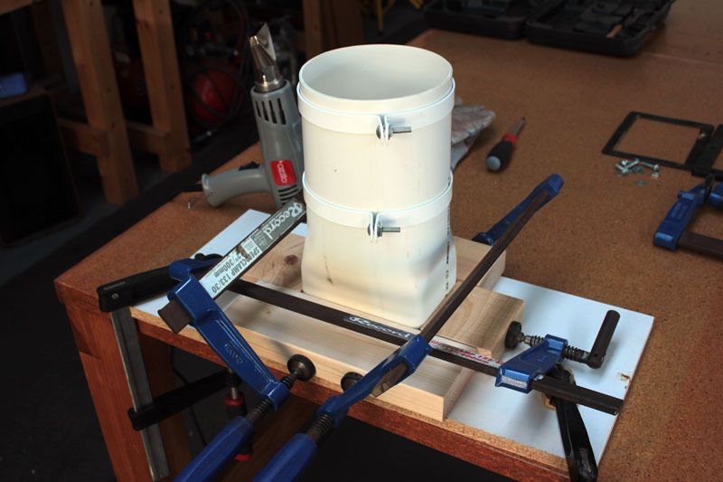
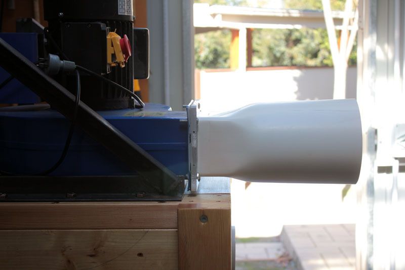
So another piece of tube was cut a little bit longer. And some clamps put on to maintain roundness where it's needed.
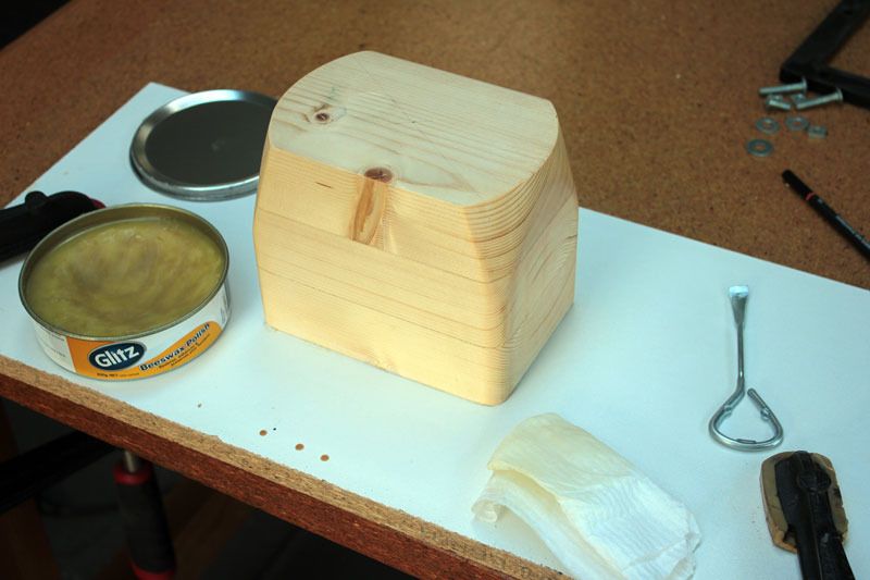
And after some thinking a form was made by gluing three 45mm pieces of pine together. This was then shaped to allow the tube to be pushed from above until the final rectangular shape is achieved at the bottom of the form. A couple of coats of bees wax is applied to help the tube slide on.
Unfortunately the actual shaping process was so quick that I couldn't take any pics. But I was surprised at just how quickly and easily this went, here, while the tube is still hot some scrap is clamped in place until it cools.
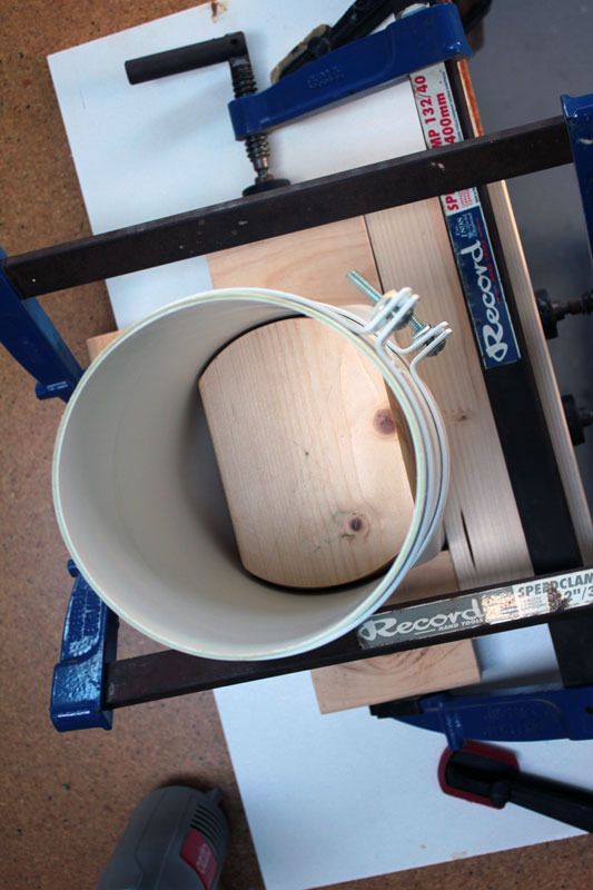
It actually took longer to get the tube off the form, but some left to right rocking got it off.
Came out good.
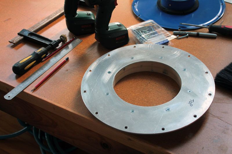
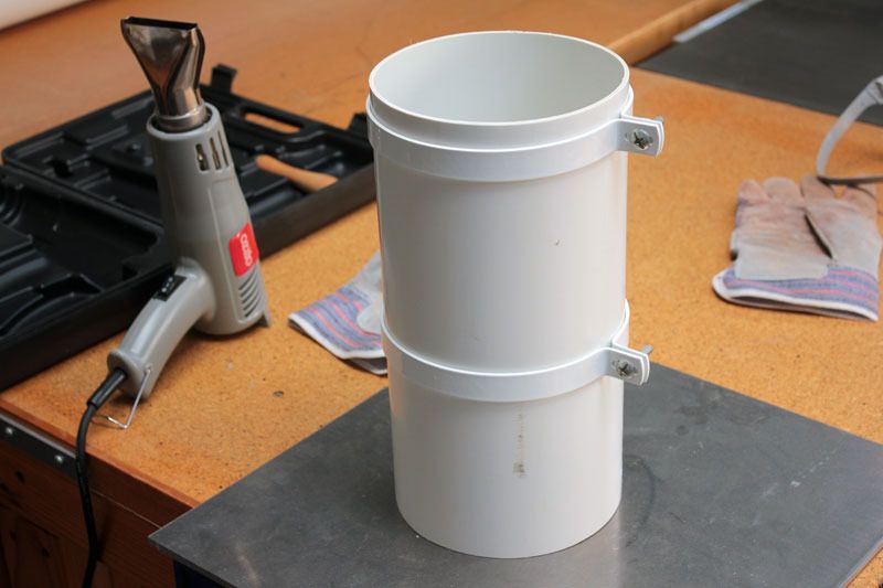
The next step is to make a collar so the tube can be fitted to the blower. I'm making this out of 10mm aluminum just because I like working with it, but this part can be made from MDF or some thick plywood.
The collar is cut out with a jigsaw and then filed to shape.
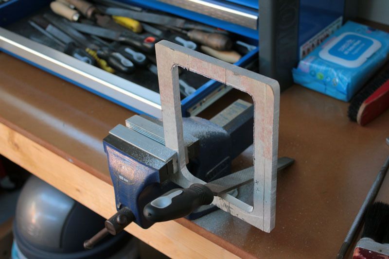
Then some holes are drilled and tapped and the two parts are fitted together with some screws and sealing compound.
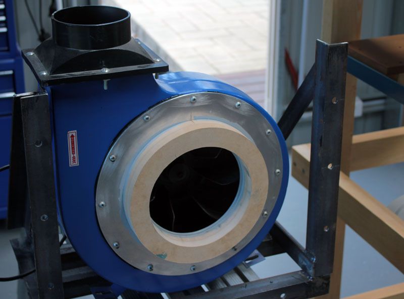
The completed part in place with the original rubber gasket and sealing compound on both sides. Though this protrudes several hundred mms it is very rigid and strong.
Next time I have some spare time, lengths of tube will be connected to the cyclone and I'll get an idea of how well it can work. Hopefully it really sucks.
-
27th April 2016, 03:31 PM #14
.
- Join Date
- Feb 2006
- Location
- Perth
- Posts
- 27,793
Thanks for answering my questions - it makes sense now.
Nice job on the transition - very tidy indeed.
Some suggestions for anyone else doing this.
Thick Al is really nice if you have it around but otherwise it's very exprensive to buy.
A cheaper way with a lot less filing etc is to use thinner (e.g. 3mm Al) plate with the hole cut undersize and then bend the 4 inside lips into right angles that can be screwed to the opening in the same way.
The bends makes the flange super stiff. I have even done this with 2mm thick galv and it has been plenty strong enough.
Use CS screws so they do not encroach into the air stream.
Counter Sinking these holes on the inside of the duct is tricky.
To do this I made myself a reverse CS bit from a large bugle headed screw.
I cut off the thread leaving a short length of unthreaded shank and the head
Then I cut slots at an angle into the side of the head so that these would cut the CS.
Put the CS bit through the hole and attach to drill - turn on drill and pull on the bit to cut the CS.
It works much better than trying to do this by using a CS and drill from the outside of the duct.
If possible Make the transition longer.
This is especially important when using a small blower like a 2HP e.g.
Transitionx.jpg
To minimise losses this should be 10 ducting radii long but this is usually completely impractical, so 5 x is often used but for a 150mm duct even that is still 750 mm long!
It is also near impossible to heat that long a piece of PVC with a hot air gun as one part cools off.
So eventually it comes down to what can be done/managed.
I have found it difficult to go much beyond about 200 mm long with PVC and that was using two heat guns.
Longer transitions are usually easier to make by using a bent/folded transition like this rectangular to round transition I made for my thicknesser hood.
This one is 330mm long.
Transitionxy.jpg
To work out the geometry look up DuctEvolution - this is a spread sheet that allow you to enter the details and it works out where all the bend go.
-
1st May 2016, 06:43 PM #15
Intermediate Member
- Join Date
- Sep 2008
- Location
- melbourne, australia
- Posts
- 32
@BobL
Good point about making the flange from thinner material. I just happen to have a lot of sheet and plate laying around.
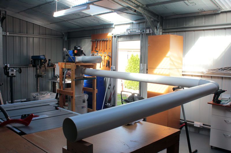
Today the system was fired up for the first time since the modifications. Some tube was connected up to the input side and the blower output was directed out the door. The length of the tube is about what will be used in one of the possible locations for the cyclone.
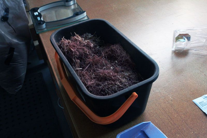
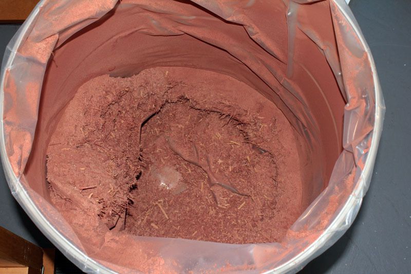
Some dust was emptied out of the dusty bag (here this is waste from the planer).
After going way over 20 amps for a brief period, the draw settled at this.
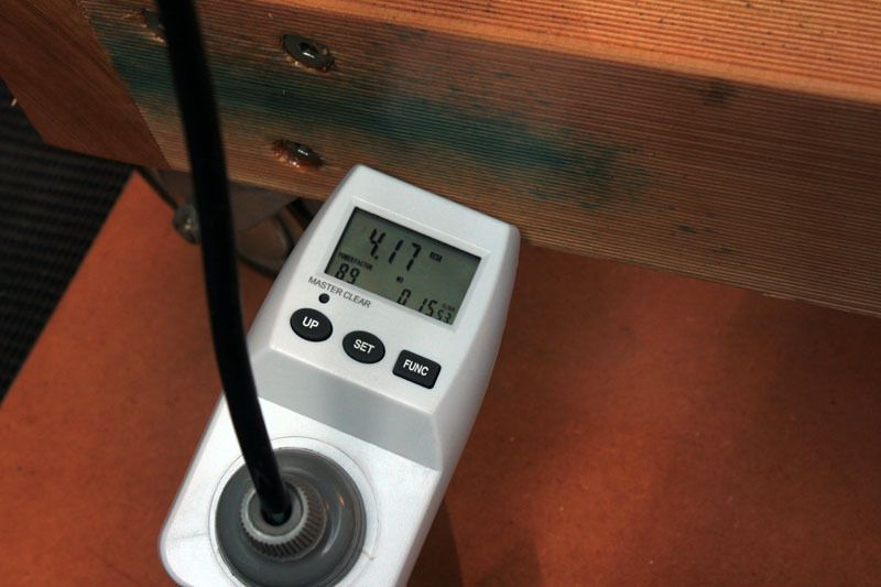
There was lots of suction and the bucket was emptied quickly. While the waste was sucked up I could see fine dust being expelled from the blower.
So the results from this brief test show that the system works as I had hoped. I don't have any instruments to measure the various properties of all this, just my eyes and ears. What do I take from this?
The system will work well at removing most of the waste from my table saw, band saw and thickness planer.
Its relatively quiet running.
If I were to make a guess at how much waste goes down the cyclone and into the bin, maybe about 99 percent. Only some of the very finest dust goes back up and through the blower. This will not be a problem as the output is vented outside.
No more clogged filters.
I don't for one second think that all the dust from my machines will be taken away and will continue to wear a mask whenever machining or sanding (and opening up the doors when finished).
I couldn't make the previously stated budget (mainly because these big tubes are not cheap) of under 500 bucks and the total cost will be closer to 650.
Here is where I've decided to put the cyclone. So far the output has been completed and the next job is to run some tube to the center of the shed.
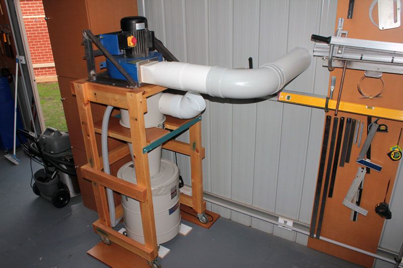
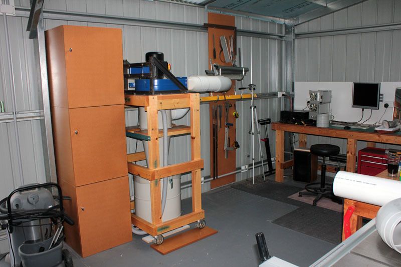
Back when the rest of the tubing is completed and a better idea of performance with running machines can be gleaned.


 Reply With Quote


Similar Threads
-
Cyclone
By fozzy767 in forum WOODWORK - GENERALReplies: 8Last Post: 8th October 2014, 07:07 PM -
WIP Cyclone
By Al B in forum METALWORK FORUMReplies: 147Last Post: 4th August 2008, 11:52 PM -
Cyclone mod. Not quite right.
By minvec in forum TRITON / GMCReplies: 8Last Post: 21st January 2007, 09:15 PM -
Fan for Cyclone
By Chris Parks in forum DUST EXTRACTIONReplies: 13Last Post: 14th February 2006, 01:41 PM -
Making cone for Cyclone
By inferno6688 in forum DUST EXTRACTIONReplies: 10Last Post: 11th January 2006, 11:28 PM
